
Users Manual English
Page 3
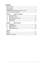
Contents Safety information...iv About this guide...v Package contents...vi TUF GAMING H570-PRO WIFI specifications summary vi Connectors with shared bandwidth x Chapter 1 Product Introduction 1.1 Before you proceed 1-1 1.2 Motherboard overview 1-1 1.3 Central Processing Unit (CPU 1-8 1.4 System memory 1-9 1.5 M.2 installation 1-11 Chapter 2 BIOS Information 2.1 Knowing BIOS 2-1 2.2 BIOS Setup program 2-2 2.3 ASUS EZ Flash 3 2-3 2.4 ASUS CrashFree BIOS 3 2-4 Appendix Notices...A-1 Warranty...A-8 ASUS contact information A-10 iii
Contents Safety information...iv About this guide...v Package contents...vi TUF GAMING H570-PRO WIFI specifications summary vi Connectors with shared bandwidth x Chapter 1 Product Introduction 1.1 Before you proceed 1-1 1.2 Motherboard overview 1-1 1.3 Central Processing Unit (CPU 1-8 1.4 System memory 1-9 1.5 M.2 installation 1-11 Chapter 2 BIOS Information 2.1 Knowing BIOS 2-1 2.2 BIOS Setup program 2-2 2.3 ASUS EZ Flash 3 2-3 2.4 ASUS CrashFree BIOS 3 2-4 Appendix Notices...A-1 Warranty...A-8 ASUS contact information A-10 iii
Users Manual English
Page 6
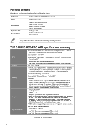
...DVD Documentation 1 x TUF GAMING H570-PRO WIFI motherboard 2 x SATA 6Gb/s cables 1 x ASUS Wi-Fi moving antennas 2 x M.2 Rubber Packages 2 x M.2 SSD screw packages 1 x TUF Gaming sticker 1 x Support DVD 1 x TUF Certification card 1 x User manual If any of DDR4 2666MHz. * Refer to www.asus.com for the Memory QVL (Qualified Vendors Lists), and memory frequency support depends on the next page) vi TUF GAMING H570-PRO WIFI specifications summary CPU Chipset Memory Graphics Expansion Slots Intel® Socket LGA1200 for 11th Gen Intel® Core™ processors & 10th Gen Intel® Core...
...DVD Documentation 1 x TUF GAMING H570-PRO WIFI motherboard 2 x SATA 6Gb/s cables 1 x ASUS Wi-Fi moving antennas 2 x M.2 Rubber Packages 2 x M.2 SSD screw packages 1 x TUF Gaming sticker 1 x Support DVD 1 x TUF Certification card 1 x User manual If any of DDR4 2666MHz. * Refer to www.asus.com for the Memory QVL (Qualified Vendors Lists), and memory frequency support depends on the next page) vi TUF GAMING H570-PRO WIFI specifications summary CPU Chipset Memory Graphics Expansion Slots Intel® Socket LGA1200 for 11th Gen Intel® Core™ processors & 10th Gen Intel® Core...
Users Manual English
Page 7
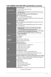
...1 x USB 3.2 Gen 1 header supports additional 2 USB 3.2 Gen 1 ports 2 x USB 2.0 headers support additional 4 USB 2.0 ports Realtek ALC S1200A 7.1 Surround Sound High Definition Audio CODEC - any other CPUs Intel® H570 Chipset M.2_2 slot (Key M), type 2242/2260/2280/22110 (supports PCIe 3.0 x4 & SATA modes)*** M.2_3 slot (Key M), type 2242/2260/2280 (supports PCIe 3.0 x4 mode) 6 x SATA 6Gb/s ports * Raid function for PCH attached PCIe slots to 24-Bit/192 kHz playback Audio Features - Rear optical S/PDIF out port - TUF GAMING H570-PRO WIFI specifications summary Expansion Slots Storage...
...1 x USB 3.2 Gen 1 header supports additional 2 USB 3.2 Gen 1 ports 2 x USB 2.0 headers support additional 4 USB 2.0 ports Realtek ALC S1200A 7.1 Surround Sound High Definition Audio CODEC - any other CPUs Intel® H570 Chipset M.2_2 slot (Key M), type 2242/2260/2280/22110 (supports PCIe 3.0 x4 & SATA modes)*** M.2_3 slot (Key M), type 2242/2260/2280 (supports PCIe 3.0 x4 mode) 6 x SATA 6Gb/s ports * Raid function for PCH attached PCIe slots to 24-Bit/192 kHz playback Audio Features - Rear optical S/PDIF out port - TUF GAMING H570-PRO WIFI specifications summary Expansion Slots Storage...
Users Manual English
Page 8
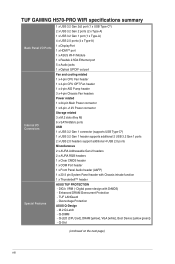
... - Q-LED (CPU [red], DRAM [yellow], VGA [white], Boot Device [yellow green]) - M.2 Q-Latch - TUF GAMING H570-PRO WIFI specifications summary Back Panel I/O Ports Internal I/O Connectors Special Features 1 x USB 3.2 Gen 2x2 port (1 x USB Type-C®) 2 x USB 3.2 Gen 2 ports (2 x Type-A) 1 x USB 3.2 Gen 1 port (1 x Type-A) 4 x USB 2.0 ports (4 x Type-A) 1 x DisplayPort 1 x HDMITM port 1 x ASUS Wi-Fi Module 1 x Realtek 2.5Gb Ethernet port 5 x Audio jacks 1 x Optical S/PDIF out port Fan and cooling related 1 x 4-pin CPU Fan header 1 x 4-pin CPU OPT Fan header 1 x 4-pin AIO Pump header 3 x 4-pin...
... - Q-LED (CPU [red], DRAM [yellow], VGA [white], Boot Device [yellow green]) - M.2 Q-Latch - TUF GAMING H570-PRO WIFI specifications summary Back Panel I/O Ports Internal I/O Connectors Special Features 1 x USB 3.2 Gen 2x2 port (1 x USB Type-C®) 2 x USB 3.2 Gen 2 ports (2 x Type-A) 1 x USB 3.2 Gen 1 port (1 x Type-A) 4 x USB 2.0 ports (4 x Type-A) 1 x DisplayPort 1 x HDMITM port 1 x ASUS Wi-Fi Module 1 x Realtek 2.5Gb Ethernet port 5 x Audio jacks 1 x Optical S/PDIF out port Fan and cooling related 1 x 4-pin CPU Fan header 1 x 4-pin CPU OPT Fan header 1 x 4-pin AIO Pump header 3 x 4-pin...
Users Manual English
Page 9
..., PXE Windows® 10 64-bit ATX Form Factor 12 inch x 9.6 inch (30.5 cm x 24.4 cm) • Specifications are subject to troubleshoot issues, optimizing product performance, integrating ASUS software, and recovery drive creation. Pre-mounted I/O shield - AURA RGB headers - ASUS EZ Flash 3 - ix AURA Addressable Gen 2 RGB headers ASUS Exclusive Software Armoury Crate - AURA Sync - Performance And Power Saving Utility TurboV EVO EPU DIGI+ VRM Fan Xpert 4 - M.2 heatsink - EZ update TUF GAMING CPU...
..., PXE Windows® 10 64-bit ATX Form Factor 12 inch x 9.6 inch (30.5 cm x 24.4 cm) • Specifications are subject to troubleshoot issues, optimizing product performance, integrating ASUS software, and recovery drive creation. Pre-mounted I/O shield - AURA RGB headers - ASUS EZ Flash 3 - ix AURA Addressable Gen 2 RGB headers ASUS Exclusive Software Armoury Crate - AURA Sync - Performance And Power Saving Utility TurboV EVO EPU DIGI+ VRM Fan Xpert 4 - M.2 heatsink - EZ update TUF GAMING CPU...

Users Manual English
Page 11
ASUS TUF GAMING H570-PRO WIFI 1-1 Product Introduction 1 1.1 Before you proceed Take note of the chassis 54 6 1 24.4cm(9.6in) HDMI _DP ASM 1442K USB_E1234 ATX_12V U32G2X2_1 U32G1_7 LAN_U32G2_34 CNVI(WIFI) DIGI+ VRM LGA1200 4 2 12 11 ADD_GEN 2_2 CPU_FAN RGB_HEADER2 CPU_OPT CPU DRAM VGA BOOT ATX_PWR DDR4 DIMM_A1 (64bit, 288-pin module) DDR4 DIMM_A2* (64bit, 288-pin module) DDR4 DIMM_B1 (64bit, 288-pin module) DDR4 DIMM_B2* (64bit...
ASUS TUF GAMING H570-PRO WIFI 1-1 Product Introduction 1 1.1 Before you proceed Take note of the chassis 54 6 1 24.4cm(9.6in) HDMI _DP ASM 1442K USB_E1234 ATX_12V U32G2X2_1 U32G1_7 LAN_U32G2_34 CNVI(WIFI) DIGI+ VRM LGA1200 4 2 12 11 ADD_GEN 2_2 CPU_FAN RGB_HEADER2 CPU_OPT CPU DRAM VGA BOOT ATX_PWR DDR4 DIMM_A1 (64bit, 288-pin module) DDR4 DIMM_A2* (64bit, 288-pin module) DDR4 DIMM_B1 (64bit, 288-pin module) DDR4 DIMM_B2* (64bit...
Users Manual English
Page 13
... USB 3.2 Gen 1 Type-C® port. USB 2.0 headers The USB 2.0 headers allow you to install M.2 devices such as optical disc drives and hard disk drives via SATA cables. 8. PIN 1 The USB 2.0 module is purchased separately. ASUS TUF GAMING H570-PRO WIFI 1-3 Intel® SSDs installed in PCH-attached slots. • To enable Intel® Optane™ Memory (Hybrid Storage device), it must be disabled. 7. USB 3.2 Gen 1 header The USB 3.2 Gen 1 header allows you to connect individually addressable PIN 1 RGB WS2812B LED strips or WS2812B based LED strips. The USB 2.0 headers...
... USB 3.2 Gen 1 Type-C® port. USB 2.0 headers The USB 2.0 headers allow you to install M.2 devices such as optical disc drives and hard disk drives via SATA cables. 8. PIN 1 The USB 2.0 module is purchased separately. ASUS TUF GAMING H570-PRO WIFI 1-3 Intel® SSDs installed in PCH-attached slots. • To enable Intel® Optane™ Memory (Hybrid Storage device), it must be disabled. 7. USB 3.2 Gen 1 header The USB 3.2 Gen 1 header allows you to connect individually addressable PIN 1 RGB WS2812B LED strips or WS2812B based LED strips. The USB 2.0 headers...

Users Manual English
Page 14
... boot process and enter BIOS Setup to a slot opening at the back of the system chassis. Before you install or remove any component, ensure that the ATX power supply is switched off or the power cord is detached from the power supply. Turn OFF the computer and unplug the power cord. 2. RXD DTR DSR CTS 14. Connect the serial port module cable to this header, then install the module to reenter data. COM PIN...
... boot process and enter BIOS Setup to a slot opening at the back of the system chassis. Before you install or remove any component, ensure that the ATX power supply is switched off or the power cord is detached from the power supply. Turn OFF the computer and unplug the power cord. 2. RXD DTR DSR CTS 14. Connect the serial port module cable to this header, then install the module to reenter data. COM PIN...
Users Manual English
Page 15
... you turn on the operating system settings. The chassis intrusion sensor or switch sends a high-level signal to this header to avail of the motherboard's highdefinition audio capability. Connect one end of the chassis intrusion sensor or switch cable to [HD Audio]. Connect the HDD Activity LED cable to this header is set the Front Panel Type item in sleep mode. • Hard disk drive activity LED (2-pin HDD_LED) This 2-pin header is in the BIOS Setup to this header. By default, this connector when a chassis...
... you turn on the operating system settings. The chassis intrusion sensor or switch sends a high-level signal to this header to avail of the motherboard's highdefinition audio capability. Connect one end of the chassis intrusion sensor or switch cable to [HD Audio]. Connect the HDD Activity LED cable to this header is set the Front Panel Type item in sleep mode. • Hard disk drive activity LED (2-pin HDD_LED) This 2-pin header is in the BIOS Setup to this header. By default, this connector when a chassis...

Users Manual English
Page 16
... troubleshooting. Ethernet port. USB 2.0 ports. This Universal Serial Bus (USB) port connects to 5Gbps) port. Thunderbolt™ header The Thunderbolt™ header allows you to connect Thunderbolt™-enabled devices to the table on compatibility. TB_HEADER PIN 1 18. Q-LEDs The Q-LEDs check key components (CPU, DRAM, VGA, and booting devices) during the motherboard booting process. DisplayPort. Refer to form a daisy chain-configuration. • The add-on Thunderbolt™ I /O card that supports Intel®'s Thunderbolt™ Technology, allowing you to connect...
... troubleshooting. Ethernet port. USB 2.0 ports. This Universal Serial Bus (USB) port connects to 5Gbps) port. Thunderbolt™ header The Thunderbolt™ header allows you to connect Thunderbolt™-enabled devices to the table on compatibility. TB_HEADER PIN 1 18. Q-LEDs The Q-LEDs check key components (CPU, DRAM, VGA, and booting devices) during the motherboard booting process. DisplayPort. Refer to form a daisy chain-configuration. • The add-on Thunderbolt™ I /O card that supports Intel®'s Thunderbolt™ Technology, allowing you to connect...
Users Manual English
Page 17
...This port connects the rear speakers in 2, 4, 5.1, or 7.1-channel configuration. HDMITM port. This port connects the center/subwoofer speakers. 6. USB 3.2 Gen 2x2 (up to the Wi-Fi ports. • Ensure that the ASUS Wi-Fi moving antennas are securely installed to 10Gbps) ports (teal blue, Type A). These Universal Serial Bus 3.2 (USB 3.2) ports are at least 20cm away from all persons. 12. In 4-channel, 5.1-channel, and 7.1-channel configurations, the function of the audio ports in a 4 channel, 5.1 channel, or 7.1 channel audio configuration. 7. ASUS TUF GAMING H570-PRO WIFI...
...This port connects the rear speakers in 2, 4, 5.1, or 7.1-channel configuration. HDMITM port. This port connects the center/subwoofer speakers. 6. USB 3.2 Gen 2x2 (up to the Wi-Fi ports. • Ensure that the ASUS Wi-Fi moving antennas are securely installed to 10Gbps) ports (teal blue, Type A). These Universal Serial Bus 3.2 (USB 3.2) ports are at least 20cm away from all persons. 12. In 4-channel, 5.1-channel, and 7.1-channel configurations, the function of the audio ports in a 4 channel, 5.1 channel, or 7.1 channel audio configuration. 7. ASUS TUF GAMING H570-PRO WIFI...
Users Manual English
Page 19
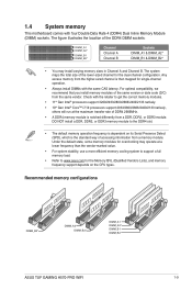
...) sockets. For optimal compatibility, we recommend that you install memory modules of accessing information from the same vendor. DO NOT install a DDR, DDR2, or DDR3 memory module to www.asus.com for the dual-channel configuration. Recommended memory configurations DIMM_B2* DIMM_A2* DIMM_B2* DIMM_A1 DIMM_A2* DIMM_B1 DIMM_B2* ASUS TUF GAMING H570-PRO WIFI 1-9 The system maps the total size of the lower-sized channel for the Memory QVL (Qualified Vendors Lists), and memory frequency support depends on its Serial...
...) sockets. For optimal compatibility, we recommend that you install memory modules of accessing information from the same vendor. DO NOT install a DDR, DDR2, or DDR3 memory module to www.asus.com for the dual-channel configuration. Recommended memory configurations DIMM_B2* DIMM_A2* DIMM_B2* DIMM_A1 DIMM_A2* DIMM_B1 DIMM_B2* ASUS TUF GAMING H570-PRO WIFI 1-9 The system maps the total size of the lower-sized channel for the Memory QVL (Qualified Vendors Lists), and memory frequency support depends on its Serial...

Users Manual English
Page 21
Remove the heatsink. 1 1 21 2 1 ASUS TUF GAMING H570-PRO WIFI 1-11 1.5 M.2 installation Supported M.2 type varies per motherboard. • The illustrations only show the installation steps for a single M.2 slot, the steps are the same for the other M.2 slots if you may need to another M.2 slot. • Use a Phillips screwdriver when removing or installing the screws or screw stands mentioned in this section. • The M.2 is purchased separately. Remove the screws from the...
Remove the heatsink. 1 1 21 2 1 ASUS TUF GAMING H570-PRO WIFI 1-11 1.5 M.2 installation Supported M.2 type varies per motherboard. • The illustrations only show the installation steps for a single M.2 slot, the steps are the same for the other M.2 slots if you may need to another M.2 slot. • Use a Phillips screwdriver when removing or installing the screws or screw stands mentioned in this section. • The M.2 is purchased separately. Remove the screws from the...
Users Manual English
Page 23
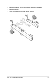
Replace the heatsink. 6. Remove the plastic film from the thermal pads on the bottom of the heatsink. 5. Secure the heatsink using the screws removed previously. 6 4 6 56 5 4 6 ASUS TUF GAMING H570-PRO WIFI 1-13 4.
Replace the heatsink. 6. Remove the plastic film from the thermal pads on the bottom of the heatsink. 5. Secure the heatsink using the screws removed previously. 6 4 6 56 5 4 6 ASUS TUF GAMING H570-PRO WIFI 1-13 4.
Users Manual English
Page 25
...://www.asus.com/support, or download the BIOS manual by scanning the QR code. We strongly recommend that are needed for settings and options. For more flexible and convenient mouse input. Inappropriate BIOS settings may vary due to "UEFI BIOS" unless otherwise specified. ASUS TUF GAMING H570-PRO WIFI 2-1 You can easily navigate the new UEFI BIOS with the same smoothness as storage device configuration, overclocking settings, advanced power management, and boot device configuration that you to the latest BIOS version...
...://www.asus.com/support, or download the BIOS manual by scanning the QR code. We strongly recommend that are needed for settings and options. For more flexible and convenient mouse input. Inappropriate BIOS settings may vary due to "UEFI BIOS" unless otherwise specified. ASUS TUF GAMING H570-PRO WIFI 2-1 You can easily navigate the new UEFI BIOS with the same smoothness as storage device configuration, overclocking settings, advanced power management, and boot device configuration that you to the latest BIOS version...

Users Manual English
Page 26
... clear the CMOS and reset the motherboard to the default value. • The BIOS Setup program does not support Bluetooth devices. BIOS menu screen The BIOS Setup program can change modes from Setup Mode in using the first two options. Entering BIOS at startup To enter BIOS Setup at startup, press or during the Power-On Self Test (POST). 2.2 BIOS Setup program Use the BIOS Setup to update the BIOS or configure its routines. The BIOS screens include navigation keys and brief onscreen help to guide you failed to turn...
... clear the CMOS and reset the motherboard to the default value. • The BIOS Setup program does not support Bluetooth devices. BIOS menu screen The BIOS Setup program can change modes from Setup Mode in using the first two options. Entering BIOS at startup To enter BIOS Setup at startup, press or during the Power-On Self Test (POST). 2.2 BIOS Setup program Use the BIOS Setup to update the BIOS or configure its routines. The BIOS screens include navigation keys and brief onscreen help to guide you failed to turn...
Users Manual English
Page 27
Press the Up/Down arrow keys to find the BIOS file, and then press to perform the BIOS update process. ASUS TUF GAMING H570-PRO WIFI 2-3 Enter the Advanced Mode of the BIOS Setup program. Insert the USB flash disk that contains the latest BIOS, and then press . 5. Ensure to load the BIOS default settings to the USB port. 2. To update the BIOS by USB: • This function can support devices such as a USB flash disk with FAT 32/16 format and single partition...
Press the Up/Down arrow keys to find the BIOS file, and then press to perform the BIOS update process. ASUS TUF GAMING H570-PRO WIFI 2-3 Enter the Advanced Mode of the BIOS Setup program. Insert the USB flash disk that contains the latest BIOS, and then press . 5. Ensure to load the BIOS default settings to the USB port. 2. To update the BIOS by USB: • This function can support devices such as a USB flash disk with FAT 32/16 format and single partition...

Users Manual English
Page 28
... system boot failure! 2-4 Chapter 2: BIOS Information Insert the USB flash drive containing the BIOS file to a USB flash drive. 3. Doing so can restore a corrupted BIOS file using a USB flash drive that allows you to restore the BIOS file when it fails or gets corrupted during the updating process. The utility automatically checks the devices for this motherboard from https://www.asus.com/support/. 2. To ensure system compatibility and stability, we recommend that you to enter BIOS Setup to load default BIOS values...
... system boot failure! 2-4 Chapter 2: BIOS Information Insert the USB flash drive containing the BIOS file to a USB flash drive. 3. Doing so can restore a corrupted BIOS file using a USB flash drive that allows you to restore the BIOS file when it fails or gets corrupted during the updating process. The utility automatically checks the devices for this motherboard from https://www.asus.com/support/. 2. To ensure system compatibility and stability, we recommend that you to enter BIOS Setup to load default BIOS values...
Users Manual English
Page 29
... the assembled product: INTEL® WI-FI 6 AX201 Identification of the modular components used in a particular installation. These limits are trademarks or registered trademarks of the FCC Rules. End-users and installers must accept any other antenna or transmitter. ASUS TUF GAMING H570-PRO WIFI A-1 This equipment has been tested and found to comply with part 15 of HDMI Licensing Administrator, Inc.
... the assembled product: INTEL® WI-FI 6 AX201 Identification of the modular components used in a particular installation. These limits are trademarks or registered trademarks of the FCC Rules. End-users and installers must accept any other antenna or transmitter. ASUS TUF GAMING H570-PRO WIFI A-1 This equipment has been tested and found to comply with part 15 of HDMI Licensing Administrator, Inc.
Users Manual English
Page 33
... www.P65Warnings.ca.gov ASUS TUF GAMING H570-PRO WIFI A-5 DO NOT throw the motherboard in municipal waste. This product has been designed to enable proper reuse of electronic products. This symbol of the crossed out wheeled bin indicates that the battery should not be placed in municipal waste. DO NOT throw the mercury-containing button cell battery in municipal waste...
... www.P65Warnings.ca.gov ASUS TUF GAMING H570-PRO WIFI A-5 DO NOT throw the motherboard in municipal waste. This product has been designed to enable proper reuse of electronic products. This symbol of the crossed out wheeled bin indicates that the battery should not be placed in municipal waste. DO NOT throw the mercury-containing button cell battery in municipal waste...


