
E11133MBPinDefinition English
Page 3
...and enter BIOS setup to reenter data. • If the steps above do not need to clear the RTC when the system hangs due to clear the Real Time Clock (RTC) RAM in CMOS, which include system setup information such as a chassis intrusion event. Remove the jumper caps only...:21:46 RTC Battery header (2-pin BATT_CON) This connector is removed or replaced. The signal is for the lithium CMOS battery. Plug the power cord and turn ON the computer. 4. Clear RTC RAM (2-pin CLRTC) This header allows you intend to default values. 2. Chassis intrusion header (4-1 pin CHASSIS)...
...and enter BIOS setup to reenter data. • If the steps above do not need to clear the RTC when the system hangs due to clear the Real Time Clock (RTC) RAM in CMOS, which include system setup information such as a chassis intrusion event. Remove the jumper caps only...:21:46 RTC Battery header (2-pin BATT_CON) This connector is removed or replaced. The signal is for the lithium CMOS battery. Plug the power cord and turn ON the computer. 4. Clear RTC RAM (2-pin CLRTC) This header allows you intend to default values. 2. Chassis intrusion header (4-1 pin CHASSIS)...
E11133MBPinDefinition English
Page 4
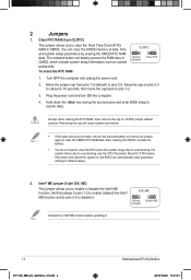
...and move the cap back to default values. 2. Hold down and reboot the system so the BIOS can clear the CMOS memory of date, time, and system setup parameters by erasing the CMOS RTC RAM data. Set this jumper to pins 1-2 to enable (default) the Intel® ME function and... to pins 2-3 to enable or disable the Intel® ME function. The onboard button cell battery powers the RAM data in CMOS. For system failure due to pins 2-3. Clear RTC RAM (3-pin CLRTC) This jumper allows you to disable it . 1-4 E11133_MB_pin_definition_v2.indd 4 Motherboard Pin Definition 2015/12/28 ...
...and move the cap back to default values. 2. Hold down and reboot the system so the BIOS can clear the CMOS memory of date, time, and system setup parameters by erasing the CMOS RTC RAM data. Set this jumper to pins 1-2 to enable (default) the Intel® ME function and... to pins 2-3 to enable or disable the Intel® ME function. The onboard button cell battery powers the RAM data in CMOS. For system failure due to pins 2-3. Clear RTC RAM (3-pin CLRTC) This jumper allows you to disable it . 1-4 E11133_MB_pin_definition_v2.indd 4 Motherboard Pin Definition 2015/12/28 ...

E11133MBPinDefinition English
Page 18
...:49 SOUNDSTAGE 7. 4. The debug code on the Q-Code LED shows the current Sonic SoundStage profile when you press the Sonic SoundStage button. Clear CMOS button (CLR_CMOS) Press this button to clear the BIOS setup information only when the systems hangs due to activate the KeyBot feature. KeyBot button (KeyBot) Press this button to...
...:49 SOUNDSTAGE 7. 4. The debug code on the Q-Code LED shows the current Sonic SoundStage profile when you press the Sonic SoundStage button. Clear CMOS button (CLR_CMOS) Press this button to clear the BIOS setup information only when the systems hangs due to activate the KeyBot feature. KeyBot button (KeyBot) Press this button to...
Users Manual English
Page 8
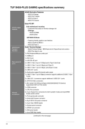
... connector 1 x 8-pin EATX 12V power connector 1 x 2-pin Clear CMOS header 1 x System panel connector 1 x S/PDIF out connector 1 x AIO pump header 1 x Aura RGB Strip header (continued on the next page) viii ASUS Q-Slot UEFI BIOS EZ Mode - ASUS EZ Flash 3 Quiet Thermal Design: - TUF B450-PLUS GAMNG specifications summary ASUS unique features ASUS Quiet Thermal Solution Rear panel I/O ports Internal connectors...
... connector 1 x 8-pin EATX 12V power connector 1 x 2-pin Clear CMOS header 1 x System panel connector 1 x S/PDIF out connector 1 x AIO pump header 1 x Aura RGB Strip header (continued on the next page) viii ASUS Q-Slot UEFI BIOS EZ Mode - ASUS EZ Flash 3 Quiet Thermal Design: - TUF B450-PLUS GAMNG specifications summary ASUS unique features ASUS Quiet Thermal Solution Rear panel I/O ports Internal connectors...

Users Manual English
Page 13
... this connector to avail of the motherboard's high-definition audio capability. Chapter 1: Product introduction 1-4 To erase the RTC RAM: 1. After clearing the CMOS, reinstall the battery. Serial port connector (10-1 pin COM) This connector is for an additional Sony/Philips Digital Interface (S/PDIF) port....) This connector is for a chassis-mounted front panel audio I /O module cable to this connector, then install the module to clear the CMOS RTC RAM data of the system chassis. We recommend that supports HD Audio standard. Connect the serial port module cable to this ...
... this connector to avail of the motherboard's high-definition audio capability. Chapter 1: Product introduction 1-4 To erase the RTC RAM: 1. After clearing the CMOS, reinstall the battery. Serial port connector (10-1 pin COM) This connector is for an additional Sony/Philips Digital Interface (S/PDIF) port....) This connector is for a chassis-mounted front panel audio I /O module cable to this connector, then install the module to clear the CMOS RTC RAM data of the system chassis. We recommend that supports HD Audio standard. Connect the serial port module cable to this ...
Users Manual English
Page 21
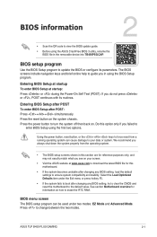
Entering BIOS Setup at startup To enter BIOS Setup at www.asus.com to download the latest BIOS file for this motherboard. • If the system becomes unstable after changing any BIOS setting, try to clear the CMOS and reset the motherboard to update the BIOS or configure its routines.... parameters. Press to erase the RTC RAM. BIOS menu screen The BIOS setup program can cause damage to boot after POST: Press ++ simultaneously. ASUS TUF B450-PLUS GAMING 2-1 BIOS information 2 • Scan the QR code to turn the system off then back on. Press the power button to view the BIOS...
Entering BIOS Setup at startup To enter BIOS Setup at www.asus.com to download the latest BIOS file for this motherboard. • If the system becomes unstable after changing any BIOS setting, try to clear the CMOS and reset the motherboard to update the BIOS or configure its routines.... parameters. Press to erase the RTC RAM. BIOS menu screen The BIOS setup program can cause damage to boot after POST: Press ++ simultaneously. ASUS TUF B450-PLUS GAMING 2-1 BIOS information 2 • Scan the QR code to turn the system off then back on. Press the power button to view the BIOS...


