BIOSUpdateE-Manual English
Page 2
... the name, model number and version, as source code archives, etc. SPECIFICATIONS AND INFORMATION CONTAINED IN THIS MANUAL ARE FURNISHED FOR INFORMATIONAL USE ONLY, AND ARE SUBJECT TO CHANGE AT ANY TIME WITHOUT NOTICE, AND SHOULD NOT BE CONSTRUED AS A COMMITMENT BY ASUS. or (2) the serial number of the product is valid to Provide Source Code of Certain Software This product...
... the name, model number and version, as source code archives, etc. SPECIFICATIONS AND INFORMATION CONTAINED IN THIS MANUAL ARE FURNISHED FOR INFORMATIONAL USE ONLY, AND ARE SUBJECT TO CHANGE AT ANY TIME WITHOUT NOTICE, AND SHOULD NOT BE CONSTRUED AS A COMMITMENT BY ASUS. or (2) the serial number of the product is valid to Provide Source Code of Certain Software This product...
BIOSUpdateE-Manual English
Page 4
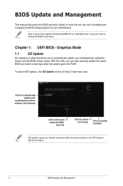
... BIOS setup program on the AI Suite 3 main menu bar. Click to automatically update your motherboard's driver, software and firmware Click to find and select the BIOS from file Click to select a boot logo Click to restore the BIOS in case you need to update the BIOS EZ Update requires an Internet connection either through a network or an ISP (Internet Service Provider). 4 BIOS Update and Management Chapter 1: UEFI BIOS - BIOS Update and Management This manual discusses the ASUS...
... BIOS setup program on the AI Suite 3 main menu bar. Click to automatically update your motherboard's driver, software and firmware Click to find and select the BIOS from file Click to select a boot logo Click to restore the BIOS in case you need to update the BIOS EZ Update requires an Internet connection either through a network or an ISP (Internet Service Provider). 4 BIOS Update and Management Chapter 1: UEFI BIOS - BIOS Update and Management This manual discusses the ASUS...
BIOSUpdateE-Manual English
Page 6
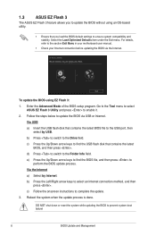
... load the BIOS default settings to the USB port, then select by Internet. Via USB a) Insert the USB flash disk that contains the latest BIOS, and then press . c) Press the Up/Down arrow keys to find the BIOS file, and then press to perform the BIOS update process. Via the Internet a) Select by USB. c) Follow the onscreen instructions to the section Exit Menu in your motherboard user manual. • Check your Internet connection...
... load the BIOS default settings to the USB port, then select by Internet. Via USB a) Insert the USB flash disk that contains the latest BIOS, and then press . c) Press the Up/Down arrow keys to find the BIOS file, and then press to perform the BIOS update process. Via the Internet a) Select by USB. c) Follow the onscreen instructions to the section Exit Menu in your motherboard user manual. • Check your Internet connection...

BIOSUpdateE-Manual English
Page 7
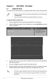
... the BIOS file to the USB port. 3. You can cause system boot failure! Recovering the BIOS To recover the BIOS: 1. When found, the utility reads the BIOS file and enters ASUS EZ Flash 3 utility automatically. 4. DO NOT shut down or reset the system while updating the BIOS! Doing so can restore a corrupted BIOS file using the motherboard support DVD or a USB flash drive that contains the updated BIOS file. • Before using this utility, rename the BIOS file in the removable device. • The BIOS file in the support DVD...
... the BIOS file to the USB port. 3. You can cause system boot failure! Recovering the BIOS To recover the BIOS: 1. When found, the utility reads the BIOS file and enters ASUS EZ Flash 3 utility automatically. 4. DO NOT shut down or reset the system while updating the BIOS! Doing so can restore a corrupted BIOS file using the motherboard support DVD or a USB flash drive that contains the updated BIOS file. • Before using this utility, rename the BIOS file in the removable device. • The BIOS file in the support DVD...
BIOSUpdateE-Manual English
Page 8
... Setup Utility - Main Ai Tweaker Advanced Monitor Boot Tool Exit Start EzFlash Press ENTER to run the utility to the Folder Info field. 5. Press the Left/Right arrow keys to switch to select and update BIOS. 3. Text Mode 2.1 ASUS EZ Flash The ASUS EZ Flash feature allows you to find the BIOS file, and then press to enable it. Reboot the system when the update process is done. • This function supports USB flash disks...
... Setup Utility - Main Ai Tweaker Advanced Monitor Boot Tool Exit Start EzFlash Press ENTER to run the utility to the Folder Info field. 5. Press the Left/Right arrow keys to switch to select and update BIOS. 3. Text Mode 2.1 ASUS EZ Flash The ASUS EZ Flash feature allows you to find the BIOS file, and then press to enable it. Reboot the system when the update process is done. • This function supports USB flash disks...
BIOSUpdateE-Manual English
Page 9
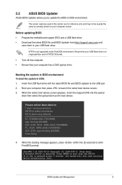
2.2 ASUS BIOS Updater ASUS BIOS Updater allows you to boot using defaults P2: ST3808110AS (76319MB) aigo miniking (250MB) UEFI: (FAT) ASUS DRW-2014L1T(4458MB) P1: ASUS DRW-2014L1T(4458MB) UEFI: (FAT) aigo miniking (250MB) Enter Setup 4. ISOLINUX 3.20 2006-08-26 Copyright (C) 1994-2005 H. Peter Anvin A Bootable DVD/CD is pressed within five (5) seconds to the USB port. 2. If no key is detected. Ensure that your USB flash drive. Please select boot device: and...
2.2 ASUS BIOS Updater ASUS BIOS Updater allows you to boot using defaults P2: ST3808110AS (76319MB) aigo miniking (250MB) UEFI: (FAT) ASUS DRW-2014L1T(4458MB) P1: ASUS DRW-2014L1T(4458MB) UEFI: (FAT) aigo miniking (250MB) Enter Setup 4. ISOLINUX 3.20 2006-08-26 Copyright (C) 1994-2005 H. Peter Anvin A Bootable DVD/CD is pressed within five (5) seconds to the USB port. 2. If no key is detected. Ensure that your USB flash drive. Please select boot device: and...
E11133MBPinDefinition English
Page 4
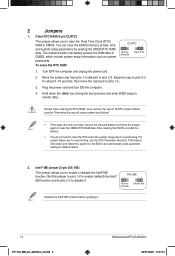
... and to pins 2-3 to enable or disable the Intel® ME function. Move the jumper cap from pins 1-2 (default) to overclocking. Shut down the key during the boot process and enter BIOS setup to overclocking, use the CPU Parameter Recall (C.P.R) feature. The onboard button cell battery powers the RAM data in CMOS. Plug the power cord and turn ON the computer. 4. Intel® ME jumper (3-pin DIS_ME) This jumper allows you to default values. 2. For system failure due to...
... and to pins 2-3 to enable or disable the Intel® ME function. Move the jumper cap from pins 1-2 (default) to overclocking. Shut down the key during the boot process and enter BIOS setup to overclocking, use the CPU Parameter Recall (C.P.R) feature. The onboard button cell battery powers the RAM data in CMOS. Plug the power cord and turn ON the computer. 4. Intel® ME jumper (3-pin DIS_ME) This jumper allows you to default values. 2. For system failure due to...

E11133MBPinDefinition English
Page 9
... EDID_GND LCD_VCC LCD_VCC LCD_VCC Enable LVDS in the BIOS setup if the LVDS output is for an internal embedded DisplayPort connection. Embedded DisplayPort (40- pin eDP) This connector is for an LCD monitor that supports Low- SATA EXPRESS connector (7-pin SATA6G, SATAEXPRESS) This connector connects to SATA 6.0 Gb/s hard disk drives via SATA 6.0 Gb/s signal cables. voltage Differential Signaling (LVDS) interface. If you installed SATA hard disk drives, you can support one SATA Express device or two SATA devices. GND RSATA_TXP1 RSATA_TXN1 GND...
... EDID_GND LCD_VCC LCD_VCC LCD_VCC Enable LVDS in the BIOS setup if the LVDS output is for an internal embedded DisplayPort connection. Embedded DisplayPort (40- pin eDP) This connector is for an LCD monitor that supports Low- SATA EXPRESS connector (7-pin SATA6G, SATAEXPRESS) This connector connects to SATA 6.0 Gb/s hard disk drives via SATA 6.0 Gb/s signal cables. voltage Differential Signaling (LVDS) interface. If you installed SATA hard disk drives, you can support one SATA Express device or two SATA devices. GND RSATA_TXP1 RSATA_TXN1 GND...

E11133MBPinDefinition English
Page 11
... is for the system power LED. Connect the HDD Activity LED cable to the HDD. +HDD_LED- Pressing the power button turns the system on the operating system settings. System panel connector (20-5 pin PANEL) This connector supports several chassis-mounted functions. • System power LED (4-pin +PWR_LED-) PANEL +PWR_LED- RESET +PWR_LED* Requires an ATX power supply • System warning speaker (4-pin SPEAKER) This 4-pin connector is in sleep or soft-off mode depending on or puts the system in sleep mode. Motherboard Pin Definition E11133_MB_pin_definition_v2.indd...
... is for the system power LED. Connect the HDD Activity LED cable to the HDD. +HDD_LED- Pressing the power button turns the system on the operating system settings. System panel connector (20-5 pin PANEL) This connector supports several chassis-mounted functions. • System power LED (4-pin +PWR_LED-) PANEL +PWR_LED- RESET +PWR_LED* Requires an ATX power supply • System warning speaker (4-pin SPEAKER) This 4-pin connector is in sleep or soft-off mode depending on or puts the system in sleep mode. Motherboard Pin Definition E11133_MB_pin_definition_v2.indd...

E11133MBPinDefinition English
Page 12
... an ATX power supply This 2-pin connector is for the system power LED. Pressing the power switch for more than four seconds while the system is ON turns the system OFF. • Reset button (2-pin RESET) This 2-pin connector is for the chassis-mounted reset button for the system power button. Connect the chassis power LED cable to this connector. Connect the HDD Activity LED cable to hear system beeps and warnings. • ATX power button/soft-off button (2-pin PWR_SW) This connector is removed or replaced. Pressing the power button turns the...
... an ATX power supply This 2-pin connector is for the system power LED. Pressing the power switch for more than four seconds while the system is ON turns the system OFF. • Reset button (2-pin RESET) This 2-pin connector is for the chassis-mounted reset button for the system power button. Connect the chassis power LED cable to this connector. Connect the HDD Activity LED cable to hear system beeps and warnings. • ATX power button/soft-off button (2-pin PWR_SW) This connector is removed or replaced. Pressing the power button turns the...

Users Manual English
Page 2
Product warranty or service will be distributed WITHOUT ANY WARRANTY and licensed under various Free Open Source Software licenses. SPECIFICATIONS AND INFORMATION CONTAINED IN THIS MANUAL ARE FURNISHED FOR INFORMATIONAL USE ONLY, AND ARE SUBJECT TO CHANGE AT ANY TIME WITHOUT NOTICE, AND SHOULD NOT BE CONSTRUED AS A COMMITMENT BY ASUS. IN NO EVENT SHALL ASUS, ITS DIRECTORS, OFFICERS, EMPLOYEES...
Product warranty or service will be distributed WITHOUT ANY WARRANTY and licensed under various Free Open Source Software licenses. SPECIFICATIONS AND INFORMATION CONTAINED IN THIS MANUAL ARE FURNISHED FOR INFORMATIONAL USE ONLY, AND ARE SUBJECT TO CHANGE AT ANY TIME WITHOUT NOTICE, AND SHOULD NOT BE CONSTRUED AS A COMMITMENT BY ASUS. IN NO EVENT SHALL ASUS, ITS DIRECTORS, OFFICERS, EMPLOYEES...

Users Manual English
Page 6
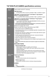
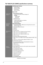
... CPU Chipset Memory AM4 socket for the following items. Motherboard Cables Accessories Application DVD Documentation ASUS TUF B450-PLUS GAMING motherboard 2 x Serial ATA 6.0 Gb/s cables 1 x I/O shield 1 x M.2 screw package 1 x TUF Certification Card 1 x TUF GAMING Sticker 1 x Support DVD 1 x User Manual If any of 1920 x 1200 @60Hz AMD Ryzen™ 2nd Generation / Ryzen™ 1st Generation processors: 1 x PCI Express 3.0 x16 slot (max. @x16 mode) AMD Ryzen™ with Radeon™ Vega Graphics processors: 1 x PCI Express 3.0 x16 slot (max. @x8 mode) AMD B450 Chipset: 1 x PCI Express...
... CPU Chipset Memory AM4 socket for the following items. Motherboard Cables Accessories Application DVD Documentation ASUS TUF B450-PLUS GAMING motherboard 2 x Serial ATA 6.0 Gb/s cables 1 x I/O shield 1 x M.2 screw package 1 x TUF Certification Card 1 x TUF GAMING Sticker 1 x Support DVD 1 x User Manual If any of 1920 x 1200 @60Hz AMD Ryzen™ 2nd Generation / Ryzen™ 1st Generation processors: 1 x PCI Express 3.0 x16 slot (max. @x16 mode) AMD Ryzen™ with Radeon™ Vega Graphics processors: 1 x PCI Express 3.0 x16 slot (max. @x8 mode) AMD B450 Chipset: 1 x PCI Express...
Users Manual English
Page 7
... processors: - 2 x Serial ATA 6.0 Gb/s connectors with RAID 0, RAID 1 and RAID 10 support AMD Ryzen™ 2nd Generation/ Ryzen™ with Radeon™ Vega Graphics/ Ryzen™ 1st Generation processors: - 1 x M.2 socket 3 with M Key, Type 2242/2260/2280/22110 (PCIe 3.0 x4 and SATA modes) storage devices support* * The M.2 Socket shares bandwidth with HD audio module in the front panel to ensure best quality * Use a chassis with the SATA_5/6 ports, and therefore the SATA_5/6 ports cannot be used when an M.2 device...
... processors: - 2 x Serial ATA 6.0 Gb/s connectors with RAID 0, RAID 1 and RAID 10 support AMD Ryzen™ 2nd Generation/ Ryzen™ with Radeon™ Vega Graphics/ Ryzen™ 1st Generation processors: - 1 x M.2 socket 3 with M Key, Type 2242/2260/2280/22110 (PCIe 3.0 x4 and SATA modes) storage devices support* * The M.2 Socket shares bandwidth with HD audio module in the front panel to ensure best quality * Use a chassis with the SATA_5/6 ports, and therefore the SATA_5/6 ports cannot be used when an M.2 device...
Users Manual English
Page 8
...support 8-channel audio output 1 x USB 3.1 Gen 1 (up to minimize damage risk Q-Design - TUF B450-PLUS GAMNG specifications summary ASUS unique features ASUS Quiet Thermal Solution Rear panel I/O ports Internal connectors ASUS Exclusive Features - ASUS AI Charger - Component-free areas to 5Gbps) connector supports additional 2 USB 3.1 Gen 1 ports 2 x USB 2.0/1.1 connectors support additional 4 USB 2.0/1.1 ports 6 x SATA 6.0 Gb/s connectors 1 x M.2 socket 3 for M Key and type 2242/2260/2280/22110 devices support(both SATA & PCIe mode) 1 x COM connector 1 x CPU Fan connector 3 x 4-pin Chassis...
...support 8-channel audio output 1 x USB 3.1 Gen 1 (up to minimize damage risk Q-Design - TUF B450-PLUS GAMNG specifications summary ASUS unique features ASUS Quiet Thermal Solution Rear panel I/O ports Internal connectors ASUS Exclusive Features - ASUS AI Charger - Component-free areas to 5Gbps) connector supports additional 2 USB 3.1 Gen 1 ports 2 x USB 2.0/1.1 connectors support additional 4 USB 2.0/1.1 ports 6 x SATA 6.0 Gb/s connectors 1 x M.2 socket 3 for M Key and type 2242/2260/2280/22110 devices support(both SATA & PCIe mode) 1 x COM connector 1 x CPU Fan connector 3 x 4-pin Chassis...
Users Manual English
Page 10
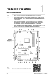
... a metal object, such as the power supply case, to avoid damaging them due to static electricity. • Before you physical injury and damage to get the detailed pin definitions. 1-1 ASUS TUF B450-PLUS GAMING Failure to do so can cause you install or remove any component, ensure that the ATX power supply is switched off or the power cord is detached from the wall socket before installing or removing the motherboard.
... a metal object, such as the power supply case, to avoid damaging them due to static electricity. • Before you physical injury and damage to get the detailed pin definitions. 1-1 ASUS TUF B450-PLUS GAMING Failure to do so can cause you install or remove any component, ensure that the ATX power supply is switched off or the power cord is detached from the wall socket before installing or removing the motherboard.
Users Manual English
Page 12
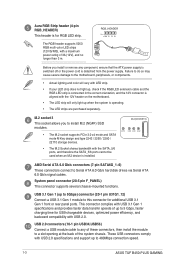
... connection speed. 1-3 ASUS TUF B450-PLUS GAMING M.2(SOCKET3) 22110 2280 2260 2242 AMD Serial ATA 6.0 Gb/s connectors (7-pin SATA6G_1~6) These connectors connect to this connector for USB-chargeable devices, optimized power efficiency, and backward compatibility with USB 3.1 Gen 1 specifications and provides faster data transfer speeds of the system chassis. These USB connectors comply with the SATA_5/6 ports, and therefore the SATA_5/6 ports cannot be used when an M.2 device is operating. • The LED strips are purchased separately. The RGB header supports...
... connection speed. 1-3 ASUS TUF B450-PLUS GAMING M.2(SOCKET3) 22110 2280 2260 2242 AMD Serial ATA 6.0 Gb/s connectors (7-pin SATA6G_1~6) These connectors connect to this connector for USB-chargeable devices, optimized power efficiency, and backward compatibility with USB 3.1 Gen 1 specifications and provides faster data transfer speeds of the system chassis. These USB connectors comply with the SATA_5/6 ports, and therefore the SATA_5/6 ports cannot be used when an M.2 device is operating. • The LED strips are purchased separately. The RGB header supports...
Users Manual English
Page 14
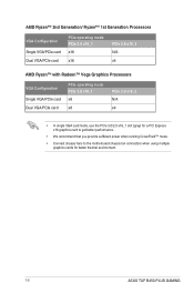
...2.0 x16_2 N/A x4 AMD Ryzen™ with Radeon™ Vega Graphics Processors VGA Configuration Single VGA/PCIe card Dual VGA/PCIe card PCIe operating mode PCIe 3.0 x16_1 x8 x8 PCIe 2.0 x16_2 N/A x4 • In single VGA card mode, use the PCIe 3.0/2.0 x16_1 slot (gray) for a PCI Express x16 graphics card to get better performance. • We recommend that you provide sufficient power when running CrossFireX™ mode. • Connect chassis fans to the motherboard chassis fan connectors when using multiple graphics cards for better thermal environment. 1-5 ASUS TUF B450-PLUS GAMING
...2.0 x16_2 N/A x4 AMD Ryzen™ with Radeon™ Vega Graphics Processors VGA Configuration Single VGA/PCIe card Dual VGA/PCIe card PCIe operating mode PCIe 3.0 x16_1 x8 x8 PCIe 2.0 x16_2 N/A x4 • In single VGA card mode, use the PCIe 3.0/2.0 x16_1 slot (gray) for a PCI Express x16 graphics card to get better performance. • We recommend that you provide sufficient power when running CrossFireX™ mode. • Connect chassis fans to the motherboard chassis fan connectors when using multiple graphics cards for better thermal environment. 1-5 ASUS TUF B450-PLUS GAMING
Users Manual English
Page 16
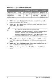
... your USB 3.1 Gen 2 devices. 9. These 4-pin Universal Serial Bus (USB) ports are controlled by the xHCI controller. • We strongly recommend that you connect USB 3.1 Gen 2 devices to the design of HD DVD, Blu-ray, and other protected content. 10. These 9-pin Universal Serial Bus (USB) ports are for USB 3.1 Gen 2 devices. • USB 3.1 Gen 1/Gen 2 devices can only be used for data storage. • Due to USB 3.1 Gen 2 ports for USB 2.0/1.1 devices. 1-7 ASUS TUF B450-PLUS GAMING These two 9-pin Universal Serial Bus (USB) ports connect to 5Gbps) port (Type-C).
... your USB 3.1 Gen 2 devices. 9. These 4-pin Universal Serial Bus (USB) ports are controlled by the xHCI controller. • We strongly recommend that you connect USB 3.1 Gen 2 devices to the design of HD DVD, Blu-ray, and other protected content. 10. These 9-pin Universal Serial Bus (USB) ports are for USB 3.1 Gen 2 devices. • USB 3.1 Gen 1/Gen 2 devices can only be used for data storage. • Due to USB 3.1 Gen 2 ports for USB 2.0/1.1 devices. 1-7 ASUS TUF B450-PLUS GAMING These two 9-pin Universal Serial Bus (USB) ports connect to 5Gbps) port (Type-C).
Users Manual English
Page 21
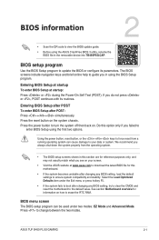
... system compatibility and stability. ASUS TUF B450-PLUS GAMING 2-1 Press the reset button on your data or system. Press to enter BIOS Setup using the first two options. BIOS information 2 • Scan the QR code to view the BIOS update guide. • Before using the BIOS Setup program. BIOS setup program Use the BIOS Setup program to update the BIOS or configure its routines. Do this section are for information on . Using the power button, reset button, or the ++ keys to boot after POST: Press ++ simultaneously. BIOS menu screen The BIOS setup...
... system compatibility and stability. ASUS TUF B450-PLUS GAMING 2-1 Press the reset button on your data or system. Press to enter BIOS Setup using the first two options. BIOS information 2 • Scan the QR code to view the BIOS update guide. • Before using the BIOS Setup program. BIOS setup program Use the BIOS Setup program to update the BIOS or configure its routines. Do this section are for information on . Using the power button, reset button, or the ++ keys to boot after POST: Press ++ simultaneously. BIOS menu screen The BIOS setup...

Users Manual English
Page 25
...help. Appendix Notices Federal Communications Commission Statement This device complies with Part 15 of the FCC Rules. Changes or modifications to this unit not expressly approved by one or more of the monitor to the graphics card is subject to the following measures: •.... • Connect the equipment to an outlet on a circuit different from that to radio communications. ASUS TUF B450-PLUS GAMING A-1 These limits are designed to assure compliance with FCC regulations. If this equipment. The use of shielded cables for compliance could void the user's authority to ...
...help. Appendix Notices Federal Communications Commission Statement This device complies with Part 15 of the FCC Rules. Changes or modifications to this unit not expressly approved by one or more of the monitor to the graphics card is subject to the following measures: •.... • Connect the equipment to an outlet on a circuit different from that to radio communications. ASUS TUF B450-PLUS GAMING A-1 These limits are designed to assure compliance with FCC regulations. If this equipment. The use of shielded cables for compliance could void the user's authority to ...


