
User Guide
Page 15
1.2 Serial number label Before requesting support from the ASUS Technical Support team, you must take note of the product, ASUS Technical Support team members can then offer a quicker and satisfying solution to your problems. TS500-E8-PS4 V2 xxS0xxxxxxxx ASUS TS500-E8-PS4 V2 1-3 With the correct serial number of the product's serial number containing 12 characters such as xxS0xxxxxxxx shown as the figure below.
1.2 Serial number label Before requesting support from the ASUS Technical Support team, you must take note of the product, ASUS Technical Support team members can then offer a quicker and satisfying solution to your problems. TS500-E8-PS4 V2 xxS0xxxxxxxx ASUS TS500-E8-PS4 V2 1-3 With the correct serial number of the product's serial number containing 12 characters such as xxS0xxxxxxxx shown as the figure below.
User Guide
Page 16
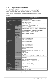
...supports Intel® LGA2011-3 Intel® Xeon® E5-2600 Processor v3 plus other latest technologies through the chipsets onboard. Model Name TS500-E8-PS4 V2 2 x Socket R3 LGA 2011-3 Processor Support / System Intel® Xeon® Processor E5-2600 v3 product Family Bus QPI 6.4...; RSTe (for Windows only; 1.3 System specifications The ASUS TS500-E8-PS4 V2 is a 5U barebone server system featuring the ASUS Z10PA-D8 Server Board. supports software RAID 0, 1, 10, and 5) Optional kits: SAS Controller ASUS PIKE 3008 8-port SAS RAID card ASUS PIKE 3108 8-port SAS HW RAID card HDD Bays ...
...supports Intel® LGA2011-3 Intel® Xeon® E5-2600 Processor v3 plus other latest technologies through the chipsets onboard. Model Name TS500-E8-PS4 V2 2 x Socket R3 LGA 2011-3 Processor Support / System Intel® Xeon® Processor E5-2600 v3 product Family Bus QPI 6.4...; RSTe (for Windows only; 1.3 System specifications The ASUS TS500-E8-PS4 V2 is a 5U barebone server system featuring the ASUS Z10PA-D8 Server Board. supports software RAID 0, 1, 10, and 5) Optional kits: SAS Controller ASUS PIKE 3008 8-port SAS RAID card ASUS PIKE 3108 8-port SAS HW RAID card HDD Bays ...
User Guide
Page 17
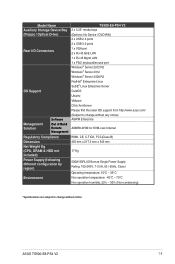
Model Name Auxiliary Storage Device Bay (Floppy / Optical Drive) TS500-E8-PS4 V2 3 x 5.25" media bays (Options: No Device / DVD-RW) 2 x USB 2.0 ports 2 x USB 3.0 ports Rear I/O Connectors 1 x VGA port ...Linux Enterprise Server OS Support CentOS Ubuntu VMware Citrix XenServer Please find the latest OS support from http://www.asus.com/ Management Solution Software Out of Band Remote Management (Subject to change without any notice) ASWM Enterprise...;C Non operation humidity: 20% - 90% (Non condensing) *Specifications are subject to change without notice. ASUS TS500-E8-PS4 V2 1-5
Model Name Auxiliary Storage Device Bay (Floppy / Optical Drive) TS500-E8-PS4 V2 3 x 5.25" media bays (Options: No Device / DVD-RW) 2 x USB 2.0 ports 2 x USB 3.0 ports Rear I/O Connectors 1 x VGA port ...Linux Enterprise Server OS Support CentOS Ubuntu VMware Citrix XenServer Please find the latest OS support from http://www.asus.com/ Management Solution Software Out of Band Remote Management (Subject to change without any notice) ASWM Enterprise...;C Non operation humidity: 20% - 90% (Non condensing) *Specifications are subject to change without notice. ASUS TS500-E8-PS4 V2 1-5

User Guide
Page 19
ASUS TS500-E8-PS4 V2 1-7 1.5 Rear panel features PS/2 mouse/keyboard port USB 2.0 ports VGA port Gigabit LAN ports USB 3.0 ports Power connector Chassis lock 120mm x 38mm system fan LAN port* Chassis intrusion switch Expansion slots *This port is for the ASUS ASMB8-iKVM controller only.
ASUS TS500-E8-PS4 V2 1-7 1.5 Rear panel features PS/2 mouse/keyboard port USB 2.0 ports VGA port Gigabit LAN ports USB 3.0 ports Power connector Chassis lock 120mm x 38mm system fan LAN port* Chassis intrusion switch Expansion slots *This port is for the ASUS ASMB8-iKVM controller only.
User Guide
Page 21
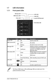
... LEDs Locate LED Display status ON OFF Blinking OFF Lighting up Green Red Description System power ON No activity Read/write data into the HDD. ASUS TS500-E8-PS4 V2 1-9 Use ASWM to backplane Installed HDD is in good condition HDD failure Green/Red Blinking HDD rebuilding using the RAID card OFF Blinking ON LAN...
... LEDs Locate LED Display status ON OFF Blinking OFF Lighting up Green Red Description System power ON No activity Read/write data into the HDD. ASUS TS500-E8-PS4 V2 1-9 Use ASWM to backplane Installed HDD is in good condition HDD failure Green/Red Blinking HDD rebuilding using the RAID card OFF Blinking ON LAN...
User Guide
Page 25
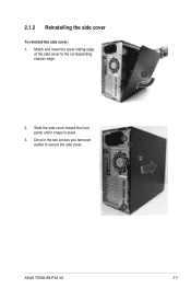
Match and insert the lower sliding edge of the side cover to secure the side cover. Slide the side cover toward the front panel until it snaps in the two screws you removed earlier to the corresponding chassis edge. 2. ASUS TS500-E8-PS4 V2 2-3 2.1.2 Reinstalling the side cover To reinstall the side cover: 1. Drive in place. 3.
Match and insert the lower sliding edge of the side cover to secure the side cover. Slide the side cover toward the front panel until it snaps in the two screws you removed earlier to the corresponding chassis edge. 2. ASUS TS500-E8-PS4 V2 2-3 2.1.2 Reinstalling the side cover To reinstall the side cover: 1. Drive in place. 3.
User Guide
Page 27
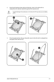
To prevent damage to the left load lever down with your thumb (A), move it is released from the retention tab (B) then gently lift the load lever (C). 2. Load lever 3. Press the right load lever with your thumb (D), move it to the right until it is released from then gently lift the load lever (F). Press the left until it to the socket pins, do not remove the PnP cap unless you are installing a CPU. ASUS TS500-E8-PS4 V2 2-5
To prevent damage to the left load lever down with your thumb (A), move it is released from the retention tab (B) then gently lift the load lever (C). 2. Load lever 3. Press the right load lever with your thumb (D), move it to the right until it is released from then gently lift the load lever (F). Press the left until it to the socket pins, do not remove the PnP cap unless you are installing a CPU. ASUS TS500-E8-PS4 V2 2-5
User Guide
Page 29
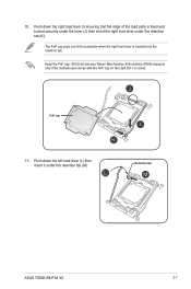
... right load lever under the retention tab (M). ASUS will process Return Merchandise Authorization (RMA) requests only if the motherboard comes with the PnP cap on the LGA 2011-3 socket. Push down the left load lever (L) then insert it under the retention tab (K). Retention tab ASUS TS500-E8-PS4 V2 2-7 Keep the PnP cap. PnP cap 11...
... right load lever under the retention tab (M). ASUS will process Return Merchandise Authorization (RMA) requests only if the motherboard comes with the PnP cap on the LGA 2011-3 socket. Push down the left load lever (L) then insert it under the retention tab (K). Retention tab ASUS TS500-E8-PS4 V2 2-7 Keep the PnP cap. PnP cap 11...

User Guide
Page 31
Connect the rear fan connector to CPU_FAN2 connector. 3. Align and click the rear fan into place. Connect the CPU heatsink fan connector to REAR_FAN1 connector. ASUS TS500-E8-PS4 V2 2-9 2.2.2 Installing the CPU heatsink To install the CPU heatsink: 1. Loose the rear fan retainers with both hands to remove the fan and unplug the rear fan connector. 2.
Connect the rear fan connector to CPU_FAN2 connector. 3. Align and click the rear fan into place. Connect the CPU heatsink fan connector to REAR_FAN1 connector. ASUS TS500-E8-PS4 V2 2-9 2.2.2 Installing the CPU heatsink To install the CPU heatsink: 1. Loose the rear fan retainers with both hands to remove the fan and unplug the rear fan connector. 2.
User Guide
Page 33
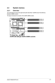
2.3 System memory 2.3.1 Overview The motherboard comes with eight (8) Double Data Rate 4 (DDR4) Dual Inline Memory Modules (DIMM) sockets. The figure illustrates the location of the DDR4 DIMM sockets: ASUS TS500-E8-PS4 V2 2-11
2.3 System memory 2.3.1 Overview The motherboard comes with eight (8) Double Data Rate 4 (DDR4) Dual Inline Memory Modules (DIMM) sockets. The figure illustrates the location of the DDR4 DIMM sockets: ASUS TS500-E8-PS4 V2 2-11
User Guide
Page 35
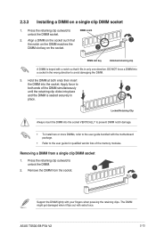
... retaining clip outward to unlock the DIMM socket. Hold the DIMM at both ends of the memory modules. DIMM notch 2. 2.3.3 Installing a DIMM on the socket. ASUS TS500-E8-PS4 V2 2-13
... retaining clip outward to unlock the DIMM socket. Hold the DIMM at both ends of the memory modules. DIMM notch 2. 2.3.3 Installing a DIMM on the socket. ASUS TS500-E8-PS4 V2 2-13
User Guide
Page 37
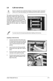
... slide the bay lock to the motherboard and other system components! You must remove the front panel assembly before installing or removing any system components. ASUS TS500-E8-PS4 V2 2-15 The lower bays (labeled 2 and 3) are available for additional 5.25-inch optical, zip, or floppy disk drives. An optical drive that comes standard/optional...
... slide the bay lock to the motherboard and other system components! You must remove the front panel assembly before installing or removing any system components. ASUS TS500-E8-PS4 V2 2-15 The lower bays (labeled 2 and 3) are available for additional 5.25-inch optical, zip, or floppy disk drives. An optical drive that comes standard/optional...
User Guide
Page 39
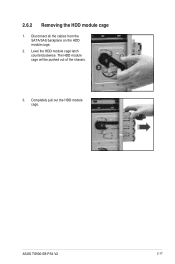
Completely pull out the HDD module cage. ASUS TS500-E8-PS4 V2 2-17 2.6.2 Removing the HDD module cage 1. Level the HDD module cage latch counterclockwise. The HDD module cage will be pushed out of the chassis. 3. Disconnect all the cables from the SATA/SAS backplane on the HDD module cage. 2.
Completely pull out the HDD module cage. ASUS TS500-E8-PS4 V2 2-17 2.6.2 Removing the HDD module cage 1. Level the HDD module cage latch counterclockwise. The HDD module cage will be pushed out of the chassis. 3. Disconnect all the cables from the SATA/SAS backplane on the HDD module cage. 2.

User Guide
Page 41
... the bay edge. 7. Place a SATA/SAS hard disk drive on the backplane. 6. Push the tray lever until just a small fraction of the tray edge protrudes. ASUS TS500-E8-PS4 V2 2-19
... the bay edge. 7. Place a SATA/SAS hard disk drive on the backplane. 6. Push the tray lever until just a small fraction of the tray edge protrudes. ASUS TS500-E8-PS4 V2 2-19

User Guide
Page 43
... you to install an expansion card. Before installing the expansion card, read the documentation that came with an expansion card lock on a flat, stable surface. 3. ASUS TS500-E8-PS4 V2 2-21 Push down the expansion card lock latch (step A) and lift up the expansion card lock (step B), as shown in less steps. Lay the system...
... you to install an expansion card. Before installing the expansion card, read the documentation that came with an expansion card lock on a flat, stable surface. 3. ASUS TS500-E8-PS4 V2 2-21 Push down the expansion card lock latch (step A) and lift up the expansion card lock (step B), as shown in less steps. Lay the system...

User Guide
Page 45
ASUS TS500-E8-PS4 V2 2-23 2.7.2 Installing an ASUS PIKE II card You can install an ASUS PIKE II card on the metal cover and then remove the metal cover, put them aside for future use. Remove the default cable from the motherboard and the backplane. 2. Remove the screw on the provided PCI-E slot onboard. To install an ASUS PIKE II card: 1.
ASUS TS500-E8-PS4 V2 2-23 2.7.2 Installing an ASUS PIKE II card You can install an ASUS PIKE II card on the metal cover and then remove the metal cover, put them aside for future use. Remove the default cable from the motherboard and the backplane. 2. Remove the screw on the provided PCI-E slot onboard. To install an ASUS PIKE II card: 1.

User Guide
Page 47
connector 1 ASUS TS500-E8-PS4 V2 2-25 Connect connector 1 on the ASUS PIKE II card to connector 1 on the backplane using the mini-SAS HD cable. 6.
connector 1 ASUS TS500-E8-PS4 V2 2-25 Connect connector 1 on the ASUS PIKE II card to connector 1 on the backplane using the mini-SAS HD cable. 6.

User Guide
Page 49
SATA ports (miniSAS connector support) connectors (system default; System auxiliary panel connector (from motherboard to front I /O board) 7. System panel connector (from motherboard to front I /O board) ASUS TS500-E8-PS4 V2 2-27 USB connector (from motherboard to SATA/SAS backplane) 6. from motherboard to front I/O board) 5. System fan connector (from system fan to motherboard) 3. Standard cables connected to the motherboard 1. 24-pin ATX power connector (from power supply to motherboard) 2. 8-pin 12V power connector (from power supply to motherboard) 4.
SATA ports (miniSAS connector support) connectors (system default; System auxiliary panel connector (from motherboard to front I /O board) 7. System panel connector (from motherboard to front I /O board) ASUS TS500-E8-PS4 V2 2-27 USB connector (from motherboard to SATA/SAS backplane) 6. from motherboard to front I/O board) 5. System fan connector (from system fan to motherboard) 3. Standard cables connected to the motherboard 1. 24-pin ATX power connector (from power supply to motherboard) 2. 8-pin 12V power connector (from power supply to motherboard) 4.

User Guide
Page 51
This side includes the power connectors and SATA/SAS interfaces for the motherboard Serial ATA connectors or the SAS card. PWR1 MSAS_HD1 Connectors MSAS_HD1 BPSMB1 PWR1 BPSMB1 Description Connects to SATA SGPIO1 connector on the motherboard or connects to SATA/SAS connectors on the ASUS PIKE II card Connects to AUX_PANEL1 connector on the motherboard Connects to 4-pin plug of the SATA/SAS backplane faces the rear panel when installed. Back side The back side of the power supply ASUS TS500-E8-PS4 V2 2-29
This side includes the power connectors and SATA/SAS interfaces for the motherboard Serial ATA connectors or the SAS card. PWR1 MSAS_HD1 Connectors MSAS_HD1 BPSMB1 PWR1 BPSMB1 Description Connects to SATA SGPIO1 connector on the motherboard or connects to SATA/SAS connectors on the ASUS PIKE II card Connects to AUX_PANEL1 connector on the motherboard Connects to 4-pin plug of the SATA/SAS backplane faces the rear panel when installed. Back side The back side of the power supply ASUS TS500-E8-PS4 V2 2-29
User Guide
Page 53
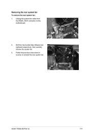
Follow the previous instructions in reverse to reinstall the rear system fan. Unplug the system fan cable from the REAR_FAN1 connector on the motherboard. 2. ASUS TS500-E8-PS4 V2 2-31 Removing the rear system fan To remove the rear system fan: 1. Shift the two hooked tabs leftward and rightward respectively, then carefully remove the system fan. 3.
Follow the previous instructions in reverse to reinstall the rear system fan. Unplug the system fan cable from the REAR_FAN1 connector on the motherboard. 2. ASUS TS500-E8-PS4 V2 2-31 Removing the rear system fan To remove the rear system fan: 1. Shift the two hooked tabs leftward and rightward respectively, then carefully remove the system fan. 3.


