User Guide
Page 13
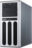
Product introduction Chapter 1 This chapter describes the general features of the server, including sections on front panel and rear panel specifications. ASUS TS100-E8-PI4
Product introduction Chapter 1 This chapter describes the general features of the server, including sections on front panel and rear panel specifications. ASUS TS100-E8-PI4
User Guide
Page 15
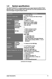
... supports Intel® LGA1150 Xeon® E3-1200 v3 processors with the latest technologies through the chipsets onboard. 1.3 System specifications The ASUS TS100-E8-PI4 is a pedestal barebone server system featuring the ASUS P9D-X/ MR server board. Model Name Processor / System Bus Core Logic Memory Total Slots Capacity Memory Type Memory Size Total PCI/PCI... America) 1 x External Serial Port 2 x RJ-45 ports 2 x USB 3.0 ports (Rear x 2) 4 x USB 2.0 ports (Front x 2, Rear x 2) 1 x VGA port 1 x PS/2 keyboard/mouse port (continued on the next page) ASUS TS100-E8-PI4 1-3
... supports Intel® LGA1150 Xeon® E3-1200 v3 processors with the latest technologies through the chipsets onboard. 1.3 System specifications The ASUS TS100-E8-PI4 is a pedestal barebone server system featuring the ASUS P9D-X/ MR server board. Model Name Processor / System Bus Core Logic Memory Total Slots Capacity Memory Type Memory Size Total PCI/PCI... America) 1 x External Serial Port 2 x RJ-45 ports 2 x USB 3.0 ports (Rear x 2) 4 x USB 2.0 ports (Front x 2, Rear x 2) 1 x VGA port 1 x PS/2 keyboard/mouse port (continued on the next page) ASUS TS100-E8-PI4 1-3
User Guide
Page 17
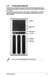
... Empty 5.25-inch bays HDD access LED Power button Reset button Power LED USB 2.0 ports Refer to section 1.7.1 Front panel LEDs for the LED descriptions. ASUS TS100-E8-PI4 1-5 1.4 Front panel features The barebone server displays a simple yet stylish front panel with easily accessible features. The drive bays, power and reset buttons, LED indicators...
... Empty 5.25-inch bays HDD access LED Power button Reset button Power LED USB 2.0 ports Refer to section 1.7.1 Front panel LEDs for the LED descriptions. ASUS TS100-E8-PI4 1-5 1.4 Front panel features The barebone server displays a simple yet stylish front panel with easily accessible features. The drive bays, power and reset buttons, LED indicators...
User Guide
Page 19
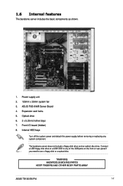
... a USB floppy disk drive or a USB ODD to use a floppy disk or a optical disc. *WARNING HAZARDOUS MOVING PARTS KEEP FINGERS AND OTHER BODY PARTS AWAY ASUS TS100-E8-PI4 1-7 Power supply unit 2. 120mm x 25mm system fan 3. Front I/O board (hidden) 8. The barebone server does not include a floppy disk drive and an optical disc drive. Expansion...
... a USB floppy disk drive or a USB ODD to use a floppy disk or a optical disc. *WARNING HAZARDOUS MOVING PARTS KEEP FINGERS AND OTHER BODY PARTS AWAY ASUS TS100-E8-PI4 1-7 Power supply unit 2. 120mm x 25mm system fan 3. Front I/O board (hidden) 8. The barebone server does not include a floppy disk drive and an optical disc drive. Expansion...

User Guide
Page 21
Hardware setup Chapter 2 This chapter lists the hardware setup procedures that you have to perform when installing or removing system components. ASUS TS100-E8-PI4
Hardware setup Chapter 2 This chapter lists the hardware setup procedures that you have to perform when installing or removing system components. ASUS TS100-E8-PI4

User Guide
Page 23
Slide the side cover toward the front panel until it snaps in the two screws you removed earlier to secure the side cover. Drive in place. 3 4. Position the side cover to the corresponding chassis edge. 2. Match and insert the lower sliding edge of the side cover to the chassis. 1 3. ASUS TS100-E8-PI4 4 4 2-3 2.1.2 Reinstalling the side cover To reinstall the side cover: 1.
Slide the side cover toward the front panel until it snaps in the two screws you removed earlier to secure the side cover. Drive in place. 3 4. Position the side cover to the corresponding chassis edge. 2. Match and insert the lower sliding edge of the side cover to the chassis. 1 3. ASUS TS100-E8-PI4 4 4 2-3 2.1.2 Reinstalling the side cover To reinstall the side cover: 1.

User Guide
Page 25
.... Press the load lever with your thumb (A), then move it is released from the CPU socket. Gold triangle mark Alignment key CPU notches Alignment key ASUS TS100-E8-PI4 2-5 2.
.... Press the load lever with your thumb (A), then move it is released from the CPU socket. Gold triangle mark Alignment key CPU notches Alignment key ASUS TS100-E8-PI4 2-5 2.

User Guide
Page 27
... and fan assembly comes in a push-pin design and requires no tool to install. • Use an LGA1150-compatible CPU heatsink and fan assembly only. ASUS TS100-E8-PI4 2-7
... and fan assembly comes in a push-pin design and requires no tool to install. • Use an LGA1150-compatible CPU heatsink and fan assembly only. ASUS TS100-E8-PI4 2-7

User Guide
Page 29
... this section. The figure illustrates the location of the DDR3 DIMM sockets: 2.3.2 Memory Configurations You may install 2 GB, 4 GB, 8GB Unbuffered with less power consumption. ASUS TS100-E8-PI4 2-9
... this section. The figure illustrates the location of the DDR3 DIMM sockets: 2.3.2 Memory Configurations You may install 2 GB, 4 GB, 8GB Unbuffered with less power consumption. ASUS TS100-E8-PI4 2-9
User Guide
Page 31
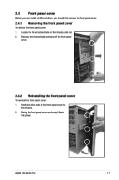
Swing the front panel cover and snap it back into place. Release the hooked tabs and take off the front panel cover. 2.4.2 Reinstalling the front panel cover To reinstall the front panel cover: 1. Locate the three hooked tabs on the chassis side rail. 2. ASUS TS100-E8-PI4 2-11 Hook the other side of the front panel cover to the chassis. 2. 2.4 Front panel cover Before you can install a 5.25-inch drive, you should first remove the front panel cover. 2.4.1 Removing the front panel cover To remove the front panel cover: 1.
Swing the front panel cover and snap it back into place. Release the hooked tabs and take off the front panel cover. 2.4.2 Reinstalling the front panel cover To reinstall the front panel cover: 1. Locate the three hooked tabs on the chassis side rail. 2. ASUS TS100-E8-PI4 2-11 Hook the other side of the front panel cover to the chassis. 2. 2.4 Front panel cover Before you can install a 5.25-inch drive, you should first remove the front panel cover. 2.4.1 Removing the front panel cover To remove the front panel cover: 1.
User Guide
Page 33
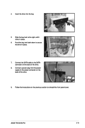
Push the bay lock latch down to the right until it clicks in place. 6 5 7. Connect a power plug from the power supply to the power connector on the previous section to the SATA connector on the back of the drive. 87 9. Slide the bay lock to secure the drive in place. 6. Insert the drive into the bay. 5. Follow the instructions on the back of the drive. 8. 4. Connect the SATA cable to reinstall the front panel cover. ASUS TS100-E8-PI4 2-13
Push the bay lock latch down to the right until it clicks in place. 6 5 7. Connect a power plug from the power supply to the power connector on the previous section to the SATA connector on the back of the drive. 87 9. Slide the bay lock to secure the drive in place. 6. Insert the drive into the bay. 5. Follow the instructions on the back of the drive. 8. 4. Connect the SATA cable to reinstall the front panel cover. ASUS TS100-E8-PI4 2-13
User Guide
Page 35
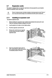
... to install an expansion card. 5 4 3 6. Lay the system on its side on a flat, stable surface. 4. 2.7 Expansion cards The system is completely seated on the slot. 6 ASUS TS100-E8-PI4 2-15
... to install an expansion card. 5 4 3 6. Lay the system on its side on a flat, stable surface. 4. 2.7 Expansion cards The system is completely seated on the slot. 6 ASUS TS100-E8-PI4 2-15
User Guide
Page 37
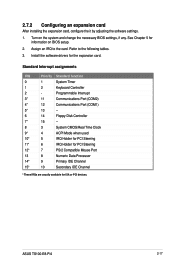
.../2 Compatible Mouse Port 13 8 Numeric Data Processor 14* 9 Primary IDE Channel 15* 10 Secondary IDE Channel * These IRQs are usually available for the expansion card. ASUS TS100-E8-PI4 2-17 Turn on BIOS setup. 2. Assign an IRQ to the following tables. 3. See Chapter 5 for information on the system and change the necessary BIOS settings...
.../2 Compatible Mouse Port 13 8 Numeric Data Processor 14* 9 Primary IDE Channel 15* 10 Secondary IDE Channel * These IRQs are usually available for the expansion card. ASUS TS100-E8-PI4 2-17 Turn on BIOS setup. 2. Assign an IRQ to the following tables. 3. See Chapter 5 for information on the system and change the necessary BIOS settings...

User Guide
Page 39
System fan connector (from motherboard to front I /O board) ASUS TS100-E8-PI4 5 6 2-19 USB connectors (from system fan to SATA devices) 5. System panel connector (from motherboard to motherboard) 4. from motherboard to motherboard) 3. SATA conectors (system default; You ...
System fan connector (from motherboard to front I /O board) ASUS TS100-E8-PI4 5 6 2-19 USB connectors (from system fan to SATA devices) 5. System panel connector (from motherboard to motherboard) 4. from motherboard to motherboard) 3. SATA conectors (system default; You ...
User Guide
Page 41
Motherboard Info Chapter 3 This chapter includes the motherboard layout and brief descriptions of the jumpers and internal connectors. ASUS TS100-E8-PI4
Motherboard Info Chapter 3 This chapter includes the motherboard layout and brief descriptions of the jumpers and internal connectors. ASUS TS100-E8-PI4
User Guide
Page 43
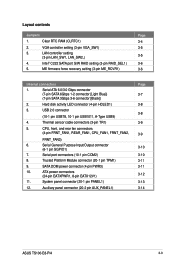
... PWR3) 10. Intel® C222 SATA port S/W RAID setting (3-pin RAID_SEL1) 5. Auxiliary panel connector (20-2 pin AUX_PANEL1) Page 3-7 3-8 3-8 3-9 3-9 3-10 3-10 3-11 3-11 3-12 3-13 3-14 ASUS TS100-E8-PI4 3-3 Layout contents Jumpers 1. VGA controller setting (3-pin VGA_SW1) 3. Serial ATA 6.0/3.0 Gbps connector (7-pin SATA 6Gbps 1-2 connector [Light Blue]) (7-pin SATA 3Gbps 3-6 connector [Black]) 2. Serial General...
... PWR3) 10. Intel® C222 SATA port S/W RAID setting (3-pin RAID_SEL1) 5. Auxiliary panel connector (20-2 pin AUX_PANEL1) Page 3-7 3-8 3-8 3-9 3-9 3-10 3-10 3-11 3-11 3-12 3-13 3-14 ASUS TS100-E8-PI4 3-3 Layout contents Jumpers 1. VGA controller setting (3-pin VGA_SW1) 3. Serial ATA 6.0/3.0 Gbps connector (7-pin SATA 6Gbps 1-2 connector [Light Blue]) (7-pin SATA 3Gbps 3-6 connector [Black]) 2. Serial General...
User Guide
Page 45
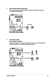
LAN controller setting (3-pin LAN_SW1, LAN_SW2) These jumpers allows you to enable or disable the onboard Intel® I210AT Gigabit LAN controllers. Set to pins 1-2 to activate the VGA feature. 3. ASUS TS100-E8-PI4 3-5 2. Set to pins 1-2 to activate the Gigabit LAN feature. VGA controller setting (3-pin VGA_SW1) This jumper allows you to enable or disable the onboard VGA controller.
LAN controller setting (3-pin LAN_SW1, LAN_SW2) These jumpers allows you to enable or disable the onboard Intel® I210AT Gigabit LAN controllers. Set to pins 1-2 to activate the VGA feature. 3. ASUS TS100-E8-PI4 3-5 2. Set to pins 1-2 to activate the Gigabit LAN feature. VGA controller setting (3-pin VGA_SW1) This jumper allows you to enable or disable the onboard VGA controller.
User Guide
Page 47
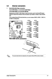
3.3 Internal connectors 1. The actual data transfer rate depends on the speed of data transfer rate. Serial ATA 6.0/3.0 Gbps connectors (7-pin SATA 6Gbps_1-2 connector [Light Blue]) (7-pin SATA 3Gbps_3-6 connector [Black]) Supported by the Intel® C222 chipset, these connectors are for the Serial ATA signal cables for Serial ATA hard disk drives that allows up to 6Gb/s or 3Gb/s of Serial ATA hard disks installed. If you installed Serial ATA hard disk drives, you can create a RAID 0, RAID 1, RAID 10, or RAID 5 configuration. ASUS TS100-E8-PI4 3-7
3.3 Internal connectors 1. The actual data transfer rate depends on the speed of data transfer rate. Serial ATA 6.0/3.0 Gbps connectors (7-pin SATA 6Gbps_1-2 connector [Light Blue]) (7-pin SATA 3Gbps_3-6 connector [Black]) Supported by the Intel® C222 chipset, these connectors are for the Serial ATA signal cables for Serial ATA hard disk drives that allows up to 6Gb/s or 3Gb/s of Serial ATA hard disks installed. If you installed Serial ATA hard disk drives, you can create a RAID 0, RAID 1, RAID 10, or RAID 5 configuration. ASUS TS100-E8-PI4 3-7
User Guide
Page 49
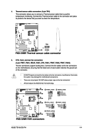
... REAR_FAN1, CPU_FAN1, FRNT_FAN2, FRNT_FAN3) The fan connectors support cooling fans. Connect the fan cables to the device that is used for temperature monitoring. ASUS TS100-E8-PI4 3-9 Connect the Thermal sensor cable to the connector and place its probe to the fan connectors on the fan connectors! • All fans feature... the ASUS Smart Fan technology. DO NOT place jumper caps on the motherboard, ensuring that the black wire of each cable matches the ground pin...
... REAR_FAN1, CPU_FAN1, FRNT_FAN2, FRNT_FAN3) The fan connectors support cooling fans. Connect the fan cables to the device that is used for temperature monitoring. ASUS TS100-E8-PI4 3-9 Connect the Thermal sensor cable to the connector and place its probe to the fan connectors on the fan connectors! • All fans feature... the ASUS Smart Fan technology. DO NOT place jumper caps on the motherboard, ensuring that the black wire of each cable matches the ground pin...

User Guide
Page 51
SATA DOM power connector (4-pin PWR3) This 4-pin connector is for 5V power of certain SATA DOM (Disk on Module) device when using an appropriate cable. A TPM system also helps enhance network security, protects digital identities, and ensures platform integrity. 9. 8. ASUS TS100-E8-PI4 3-11 Trusted Platform Module connector (20-1 pin TPM1) This connector supports a Trusted Platform Module (TPM) system, which can securely store keys, digital certificates, passwords, and data.
SATA DOM power connector (4-pin PWR3) This 4-pin connector is for 5V power of certain SATA DOM (Disk on Module) device when using an appropriate cable. A TPM system also helps enhance network security, protects digital identities, and ensures platform integrity. 9. 8. ASUS TS100-E8-PI4 3-11 Trusted Platform Module connector (20-1 pin TPM1) This connector supports a Trusted Platform Module (TPM) system, which can securely store keys, digital certificates, passwords, and data.


