
User Guide
Page 5
Contents 4.4.11 Intel Server Platform Services 4-24 4.4.12 Onboard LAN Configuration 4-25 4.4.13 MIO Card Configuration 4-25 4.4.14 Serial Port Console Redirection 4-26 4.4.15 Runtime Error Logging Support 4-29 4.4....
Contents 4.4.11 Intel Server Platform Services 4-24 4.4.12 Onboard LAN Configuration 4-25 4.4.13 MIO Card Configuration 4-25 4.4.14 Serial Port Console Redirection 4-26 4.4.15 Runtime Error Logging Support 4-29 4.4....

User Guide
Page 8
...yourself. Use the power cable with the same or equivalent type recommended by trained service personnel only. • Before operating the server, carefully read all the manuals included with a three-wire power cable and plug for assistance when moving or carrying the system.... stable surface. Replace only with a properly grounded electrical outlet to be performed by the manufacturer. This server system is equipped with the server package. • Before using the server, make sure all cables are correctly connected and the power cables are unplugged before relocating the system. ...
...yourself. Use the power cable with the same or equivalent type recommended by trained service personnel only. • Before operating the server, carefully read all the manuals included with a three-wire power cable and plug for assistance when moving or carrying the system.... stable surface. Replace only with a properly grounded electrical outlet to be performed by the manufacturer. This server system is equipped with the server package. • Before using the server, make sure all cables are correctly connected and the power cables are unplugged before relocating the system. ...

User Guide
Page 10
... jumpers and internal connectors. 4. Contents This guide contains the following parts: 1. Chapter 3: Motherboard information This chapter includes the motherboard layout and brief descriptions of configuring a server. Chapter 1: Product Introduction This chapter describes the general features of the...
... jumpers and internal connectors. 4. Contents This guide contains the following parts: 1. Chapter 3: Motherboard information This chapter includes the motherboard layout and brief descriptions of configuring a server. Chapter 1: Product Introduction This chapter describes the general features of the...

User Guide
Page 11
.... + + If you perform certain tasks properly, take note of the following sources for additional information, and for all ASUS hardware and software products. Used to set up and use the proprietary ASUS server management utility. 2. ASUS Server Web-based Management (ASWM) user guide This manual tells how to emphasize a word or a phrase. Refer to complete...
.... + + If you perform certain tasks properly, take note of the following sources for additional information, and for all ASUS hardware and software products. Used to set up and use the proprietary ASUS server management utility. 2. ASUS Server Web-based Management (ASWM) user guide This manual tells how to emphasize a word or a phrase. Refer to complete...
User Guide
Page 13
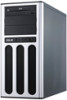
ASUS TS100-E8-PI4 Product introduction Chapter 1 This chapter describes the general features of the server, including sections on front panel and rear panel specifications.
ASUS TS100-E8-PI4 Product introduction Chapter 1 This chapter describes the general features of the server, including sections on front panel and rear panel specifications.

User Guide
Page 14
... your system package for the following items. Model Name TS100-E8-PI4 Chassis ASUS T11 Pedestal Chassis Motherboard ASUS P9D-X/MR Server Board Component 1 x 300W Single Power Supply 1 x 120mm x 25mm System Fan 4 x SATA Cables 8 x HDD plastic rails (2 pcs per HDD) 1 x Front I/O Board (FPB-R9) Accessories 1 x TS100-E8-PI4 User's Guide 1 x TS100-E8-PI4 Support CD 1 x Bag of Screws 1 x AC Power Cable Optional...
... your system package for the following items. Model Name TS100-E8-PI4 Chassis ASUS T11 Pedestal Chassis Motherboard ASUS P9D-X/MR Server Board Component 1 x 300W Single Power Supply 1 x 120mm x 25mm System Fan 4 x SATA Cables 8 x HDD plastic rails (2 pcs per HDD) 1 x Front I/O Board (FPB-R9) Accessories 1 x TS100-E8-PI4 User's Guide 1 x TS100-E8-PI4 Support CD 1 x Bag of Screws 1 x AC Power Cable Optional...
User Guide
Page 15
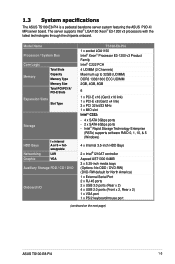
... America) 1 x External Serial Port 2 x RJ-45 ports 2 x USB 3.0 ports (Rear x 2) 4 x USB 2.0 ports (Front x 2, Rear x 2) 1 x VGA port 1 x PS/2 keyboard/mouse port (continued on the next page) ASUS TS100-E8-PI4 1-3 The server supports Intel® LGA1150 Xeon® E3-1200 v3 processors with the latest technologies through the chipsets onboard.
... America) 1 x External Serial Port 2 x RJ-45 ports 2 x USB 3.0 ports (Rear x 2) 4 x USB 2.0 ports (Front x 2, Rear x 2) 1 x VGA port 1 x PS/2 keyboard/mouse port (continued on the next page) ASUS TS100-E8-PI4 1-3 The server supports Intel® LGA1150 Xeon® E3-1200 v3 processors with the latest technologies through the chipsets onboard.

User Guide
Page 16
...x DD) Net Weight Kg (CPU, DRAM & HDD not inclu ded) Power Supply Power Rating Environment Windows® Server 2012 64-bit Windows® Server 2008 Enterprise SP2 64-bit Windows® Server 2008 R2 Enterprise SP1 64-bit RedHat® Enterprise Linux AS 5.8/6.2/6.3 64-bit CentOS 5.6/6.2/6.3 64-bit Ubuntu 12.04... 64-bit Optional Anti-Virus CD Pack ASUS ASWM Enterprise 436.8 mm x 200 mm x 478.8 mm 15 Kg 300W Bronze 80PLUS Single ...
...x DD) Net Weight Kg (CPU, DRAM & HDD not inclu ded) Power Supply Power Rating Environment Windows® Server 2012 64-bit Windows® Server 2008 Enterprise SP2 64-bit Windows® Server 2008 R2 Enterprise SP1 64-bit RedHat® Enterprise Linux AS 5.8/6.2/6.3 64-bit CentOS 5.6/6.2/6.3 64-bit Ubuntu 12.04... 64-bit Optional Anti-Virus CD Pack ASUS ASWM Enterprise 436.8 mm x 200 mm x 478.8 mm 15 Kg 300W Bronze 80PLUS Single ...
User Guide
Page 17
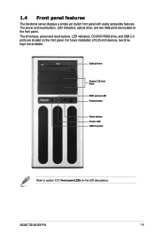
... LED USB 2.0 ports Refer to section 1.7.1 Front panel LEDs for the LED descriptions. ASUS TS100-E8-PI4 1-5 The drive bays, power and reset buttons, LED indicators, CD/DVD-ROM drive, and USB 2.0 ports are located on the front panel. 1.4 Front panel features The barebone server displays a simple yet stylish front panel with easily accessible features.
... LED USB 2.0 ports Refer to section 1.7.1 Front panel LEDs for the LED descriptions. ASUS TS100-E8-PI4 1-5 The drive bays, power and reset buttons, LED indicators, CD/DVD-ROM drive, and USB 2.0 ports are located on the front panel. 1.4 Front panel features The barebone server displays a simple yet stylish front panel with easily accessible features.
User Guide
Page 19
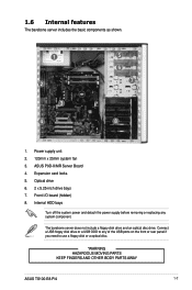
...a USB ODD to use a floppy disk or a optical disc. *WARNING HAZARDOUS MOVING PARTS KEEP FINGERS AND OTHER BODY PARTS AWAY ASUS TS100-E8-PI4 1-7 Optical drive 6. 2 x 5.25-inch drive bays 7. The barebone server does not include a floppy disk drive and an optical disc drive. Internal HDD bays Turn off the system power and detach... supply before removing or replacing any of the USB ports on the front or rear panel if you need to any system component. ASUS P9D-X/MR Server Board 4. Expansion card locks 5. Power supply unit 2. 120mm x 25mm system fan 3. 1.6 Internal features The barebone...
...a USB ODD to use a floppy disk or a optical disc. *WARNING HAZARDOUS MOVING PARTS KEEP FINGERS AND OTHER BODY PARTS AWAY ASUS TS100-E8-PI4 1-7 Optical drive 6. 2 x 5.25-inch drive bays 7. The barebone server does not include a floppy disk drive and an optical disc drive. Internal HDD bays Turn off the system power and detach... supply before removing or replacing any of the USB ports on the front or rear panel if you need to any system component. ASUS P9D-X/MR Server Board 4. Expansion card locks 5. Power supply unit 2. 120mm x 25mm system fan 3. 1.6 Internal features The barebone...

User Guide
Page 22
... inside the chassis that can cause injury, such as the CPU fan, rear fan, and other sharp-edged parts. • The images of the barebone server shown in this section are for reference purposes only and may not exactly match the model you unplug the power cord before removing the side...
... inside the chassis that can cause injury, such as the CPU fan, rear fan, and other sharp-edged parts. • The images of the barebone server shown in this section are for reference purposes only and may not exactly match the model you unplug the power cord before removing the side...

User Guide
Page 34
Carefully insert the HDD with four (4) screws. 2. Attach the bundled plastic HDD rails and secure it with the plastic HDD rails assembly all the way into the drive bay. 3. Connect the SATA cable to the power connector on the back of the drive. 4 3 2-14 Chapter 2: Hardware setup 2.6 Hard disk drives (HDD) The server system supports four (4) Serial ATA hard disk drives with plastic HDD rails. To install a Serial ATA hard disk drive: 1. Connect a power plug from the power supply to the HDD SATA connector. 2 4.
Carefully insert the HDD with four (4) screws. 2. Attach the bundled plastic HDD rails and secure it with the plastic HDD rails assembly all the way into the drive bay. 3. Connect the SATA cable to the power connector on the back of the drive. 4 3 2-14 Chapter 2: Hardware setup 2.6 Hard disk drives (HDD) The server system supports four (4) Serial ATA hard disk drives with plastic HDD rails. To install a Serial ATA hard disk drive: 1. Connect a power plug from the power supply to the HDD SATA connector. 2 4.

User Guide
Page 77
... Mode] [EPP-1.7 and SPP Mode] [ECP Mode] [ECP and EPP 1.9 Mode] [ECP and EPP 1.7 Mode] 4.4.11 Intel Server Platform Services This item displays the information of -POST Status : EOP disabled in POST ASUS TS100-E8-PI4 4-23 IRQ=5] [IO=378h: IRQ=5, 6, 7, 10, 11, 12] [IO=278h; Aptio Setup Utility - Advanced Intel Sever Platform... NM FW Status Value : 0x80000001 BIOS Booting Mode : Power Optimized Mode Cores Disabled : 0 ME FW SKU Information : Node Manager End-of the Intel Server Platform Services configured in this menu allow you to set the parallel port configuration.
... Mode] [EPP-1.7 and SPP Mode] [ECP Mode] [ECP and EPP 1.9 Mode] [ECP and EPP 1.7 Mode] 4.4.11 Intel Server Platform Services This item displays the information of -POST Status : EOP disabled in POST ASUS TS100-E8-PI4 4-23 IRQ=5] [IO=378h: IRQ=5, 6, 7, 10, 11, 12] [IO=278h; Aptio Setup Utility - Advanced Intel Sever Platform... NM FW Status Value : 0x80000001 BIOS Booting Mode : Power Optimized Mode Cores Disabled : 0 ME FW SKU Information : Node Manager End-of the Intel Server Platform Services configured in this menu allow you to set the parallel port configuration.

User Guide
Page 80
... Putty. Configuration options: [9600] [19200] [38400] [57600] [115200] Flow Control [None] Allows you to enable the VT -UTF8 Combination Key Support for Out-of a Windows Server OS through a serial port. Out-of-Band Mgmt Port [COM1] Allows remote management of -Band Management/Windows Emergency Management Services (EMS) Settings The following items...
... Putty. Configuration options: [9600] [19200] [38400] [57600] [115200] Flow Control [None] Allows you to enable the VT -UTF8 Combination Key Support for Out-of a Windows Server OS through a serial port. Out-of-Band Mgmt Port [COM1] Allows remote management of -Band Management/Windows Emergency Management Services (EMS) Settings The following items...

User Guide
Page 98
... field indicates the maximum allowed capacity. 8. From the following are typical values: RAID 0: 128KB RAID 10: 64KB RAID 5: 64KB We recommend a lower stripe size for server systems, and a higher stripe size for multimedia computer systems used mainly for RAID 0, 10 and 5 only) then press . Are you sure you want to use...
... field indicates the maximum allowed capacity. 8. From the following are typical values: RAID 0: 128KB RAID 10: 64KB RAID 5: 64KB We recommend a lower stripe size for server systems, and a higher stripe size for multimedia computer systems used mainly for RAID 0, 10 and 5 only) then press . Are you sure you want to use...

User Guide
Page 107
..., and Select additional disks to 128 KB. The following are typical values: RAID 0: 128KB RAID 10: 64KB RAID 5: 64KB We recommend a lower stripe size for server systems, and a higher stripe size for multimedia computer systems used mainly for RAID 0, 10 and 5 only) and click OK. The available stripe size values range... in Volumes field. 2 From the Volume Properties field, select Type:RAID 1 Change type. 3. Click the SATA array items you want to change in Volume Properties: 1. ASUS TS100-E8-PI4 5-15
..., and Select additional disks to 128 KB. The following are typical values: RAID 0: 128KB RAID 10: 64KB RAID 5: 64KB We recommend a lower stripe size for server systems, and a higher stripe size for multimedia computer systems used mainly for RAID 0, 10 and 5 only) and click OK. The available stripe size values range... in Volumes field. 2 From the Volume Properties field, select Type:RAID 1 Change type. 3. Click the SATA array items you want to change in Volume Properties: 1. ASUS TS100-E8-PI4 5-15

User Guide
Page 112
...C22x INTEL RAID Driver and press to go to boot from the support DVD. C22x INTEL RAID Driver Windows 32 bit(AHCI / AHCI RAID) Windows Server 2012 64 bit (AHCI / AHCI RAID) Back Exit 6-2 Chapter 6: Driver installation Exit the BIOS Setup and restart your computer. 3. Restart your ...BIOS Setup. 4. From the C22x Intel RAID Driver sub-menu, use a USB floppy drive when creating a SATA RAID driver disk. Save your server system, you are now ready to install an operating system to install the RAID controller drivers during OS installation. 6.1.1 Creating a RAID driver disk ...
...C22x INTEL RAID Driver and press to go to boot from the support DVD. C22x INTEL RAID Driver Windows 32 bit(AHCI / AHCI RAID) Windows Server 2012 64 bit (AHCI / AHCI RAID) Back Exit 6-2 Chapter 6: Driver installation Exit the BIOS Setup and restart your computer. 3. Restart your ...BIOS Setup. 4. From the C22x Intel RAID Driver sub-menu, use a USB floppy drive when creating a SATA RAID driver disk. Save your server system, you are now ready to install an operating system to install the RAID controller drivers during OS installation. 6.1.1 Creating a RAID driver disk ...

User Guide
Page 114
Click Load Driver. 6-4 Chapter 6: Driver installation When prompted to start installing Windows Server 2008. 2. Boot the computer using the Windows® Server 2008 OS installation disc. 6.1.2 Installing the RAID controller driver During Windows® Server 2008 OS installation To install the RAID controller driver when installing Windows® Server 2008 OS 1. Follow the screen instructions to choose a type of installation, click Custom (advanced). 3.
Click Load Driver. 6-4 Chapter 6: Driver installation When prompted to start installing Windows Server 2008. 2. Boot the computer using the Windows® Server 2008 OS installation disc. 6.1.2 Installing the RAID controller driver During Windows® Server 2008 OS installation To install the RAID controller driver when installing Windows® Server 2008 OS 1. Follow the screen instructions to choose a type of installation, click Custom (advanced). 3.

User Guide
Page 115
4. Locate the driver in your system, eject the Windows OS installation disc and replace with the Windows Server installation disc. ASUS TS100-E8-PI4 6-5 Follow succeeding screen instructions to install Windows and click Next. 8. Select the drive to continue. If you have only one optical drive installed in the ...
4. Locate the driver in your system, eject the Windows OS installation disc and replace with the Windows Server installation disc. ASUS TS100-E8-PI4 6-5 Follow succeeding screen instructions to install Windows and click Next. 8. Select the drive to continue. If you have only one optical drive installed in the ...

User Guide
Page 116
... support DVD that you can install to locate the file ASSETUP.EXE from the BIN folder. Visit the ASUS website (www.asus.com) for the latest updates on Windows® Server 2008 R2 and Windows® Server 2012. 6.3 Running the Support DVD When you place the support DVD into the optical drive, the DVD...
... support DVD that you can install to locate the file ASSETUP.EXE from the BIN folder. Visit the ASUS website (www.asus.com) for the latest updates on Windows® Server 2008 R2 and Windows® Server 2012. 6.3 Running the Support DVD When you place the support DVD into the optical drive, the DVD...
