User Guide
Page 15
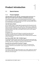
... to -point links, which increases bandwidth and enhances the system's performance. Chapter 1 ASUS SABERTOOTH Z97 MARK 1/USB 3.1 1-1 Quad-GPU SLI and Quad GPU CrossFireX™ Support This motherboard features the most powerful Intel® Z97 platform that features data transfer rates of DDR3 1866 / 1600 / 1333 MHz to boost...catch up to 10 Gb/s, allowing your system to meet the higher bandwidth requirements of the same speed. Intel® Z97 Express Chipset Intel® Z97 Express Chipset is the PCI Express bus standard that supports the LGA1150 socket for the 4th, New 4th, and 5th...
... to -point links, which increases bandwidth and enhances the system's performance. Chapter 1 ASUS SABERTOOTH Z97 MARK 1/USB 3.1 1-1 Quad-GPU SLI and Quad GPU CrossFireX™ Support This motherboard features the most powerful Intel® Z97 platform that features data transfer rates of DDR3 1866 / 1600 / 1333 MHz to boost...catch up to 10 Gb/s, allowing your system to meet the higher bandwidth requirements of the same speed. Intel® Z97 Express Chipset Intel® Z97 Express Chipset is the PCI Express bus standard that supports the LGA1150 socket for the 4th, New 4th, and 5th...
User Guide
Page 17
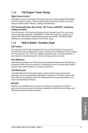
... better performance, and durability during the most extreme usage. 1.1.4 "Safe & Stable!" Chapter 1 ASUS SABERTOOTH Z97 MARK 1/USB 3.1 1-3 MemOK! 1.1.3 "TUF Engine" Power Design Digital Power Control ASUS DIGI+ Power Control features the revolutionary and innovative digital VRM, DRAM, and CPU Voltage controllers. ...These controllers offers ultra-precise memory and voltage tuning for optimal system efficiency, stability and performance. The ASUS exclusive AntiStatic chip and circuit design, and the I /O filter and special shields that help reduce dust build-up...
... better performance, and durability during the most extreme usage. 1.1.4 "Safe & Stable!" Chapter 1 ASUS SABERTOOTH Z97 MARK 1/USB 3.1 1-3 MemOK! 1.1.3 "TUF Engine" Power Design Digital Power Control ASUS DIGI+ Power Control features the revolutionary and innovative digital VRM, DRAM, and CPU Voltage controllers. ...These controllers offers ultra-precise memory and voltage tuning for optimal system efficiency, stability and performance. The ASUS exclusive AntiStatic chip and circuit design, and the I /O filter and special shields that help reduce dust build-up...
User Guide
Page 19
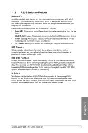
...even when the system is automatically updated even without entering the existing BIOS or operating system. Chapter 1 ASUS SABERTOOTH Z97 MARK 1/USB 3.1 1-5 Conveniently use software package. USB BIOS Flashback USB BIOS Flashback offers a hassle-free updating solution for about three seconds, and the UEFI BIOS is powered... files between your smart devices such as smartphones, tablets and more enjoyable home entertainment. 1.1.6 ASUS Exclusive Features Remote GO! USB Charger+ With a dedicated onboard controller, quick-charge all -in-one simple-to-use and enjoy these...
...even when the system is automatically updated even without entering the existing BIOS or operating system. Chapter 1 ASUS SABERTOOTH Z97 MARK 1/USB 3.1 1-5 Conveniently use software package. USB BIOS Flashback USB BIOS Flashback offers a hassle-free updating solution for about three seconds, and the UEFI BIOS is powered... files between your smart devices such as smartphones, tablets and more enjoyable home entertainment. 1.1.6 ASUS Exclusive Features Remote GO! USB Charger+ With a dedicated onboard controller, quick-charge all -in-one simple-to-use and enjoy these...
User Guide
Page 21
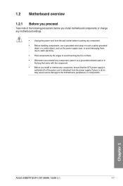
... the power supply case, to avoid damaging them due to static electricity. • Hold components by the edges to the motherboard, peripherals, or components. Chapter 1 ASUS SABERTOOTH Z97 MARK 1/USB 3.1 1-7 1.2 Motherboard overview 1.2.1 Before you proceed Take note of the following precautions before you install or remove any component, ensure that the ATX power supply is...
... the power supply case, to avoid damaging them due to static electricity. • Hold components by the edges to the motherboard, peripherals, or components. Chapter 1 ASUS SABERTOOTH Z97 MARK 1/USB 3.1 1-7 1.2 Motherboard overview 1.2.1 Before you proceed Take note of the following precautions before you install or remove any component, ensure that the ATX power supply is...
User Guide
Page 23
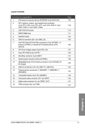
...33 1-10 1-11 1-25 1-30 1-29 1-27 1-26 1-37 1-36 1-30 1-32 1-34 1-38 1-34 1-31 1-37 Chapter 1 ASUS SABERTOOTH Z97 MARK 1/USB 3.1 1-9 LGA1150 CPU socket 4. ASMedia® Serial ATA 6.0 Gb/s connectors (7-pin SATA6G_E1E2 [beige]) 13. Layout contents Connectors/Jumpers/Slots 1. Thermal ...System panel connector (20-8 pin PANEL) 12. Digital audio connector (4-1 pin SPDIF_OUT) 18. USB 2.0 connectors (10-1 pin USB1112, USB1314) 14. DirectKey connector (2-pin DRCT) 11. Intel® Z97 Serial ATA 6.0 Gb/s connectors (7-pin SATA6G_1-2 [brown]; ATX power connectors (24-pin ...
...33 1-10 1-11 1-25 1-30 1-29 1-27 1-26 1-37 1-36 1-30 1-32 1-34 1-38 1-34 1-31 1-37 Chapter 1 ASUS SABERTOOTH Z97 MARK 1/USB 3.1 1-9 LGA1150 CPU socket 4. ASMedia® Serial ATA 6.0 Gb/s connectors (7-pin SATA6G_E1E2 [beige]) 13. Layout contents Connectors/Jumpers/Slots 1. Thermal ...System panel connector (20-8 pin PANEL) 12. Digital audio connector (4-1 pin SPDIF_OUT) 18. USB 2.0 connectors (10-1 pin USB1112, USB1314) 14. DirectKey connector (2-pin DRCT) 11. Intel® Z97 Serial ATA 6.0 Gb/s connectors (7-pin SATA6G_1-2 [brown]; ATX power connectors (24-pin ...
User Guide
Page 25
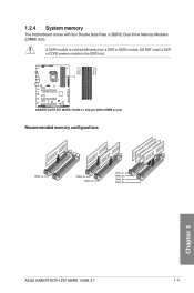
Recommended memory configurations Chapter 1 ASUS SABERTOOTH Z97 MARK 1/USB 3.1 1-11 DO NOT install a DDR or DDR2 memory module to the DDR3 slot. A DDR3 module is notched differently from a DDR or DDR2 module. 1.2.4 System memory The motherboard comes with four Double Data Rate 3 (DDR3) Dual Inline Memory Modules (DIMM) slots.
Recommended memory configurations Chapter 1 ASUS SABERTOOTH Z97 MARK 1/USB 3.1 1-11 DO NOT install a DDR or DDR2 memory module to the DDR3 slot. A DDR3 module is notched differently from a DDR or DDR2 module. 1.2.4 System memory The motherboard comes with four Double Data Rate 3 (DDR3) Dual Inline Memory Modules (DIMM) slots.
User Guide
Page 31
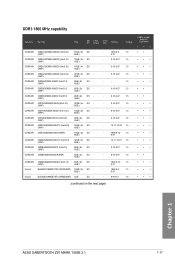
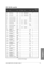
...; • • • • • • • • • • • • • • • • • • • (continued on the next page) Chapter 1 ASUS SABERTOOTH Z97 MARK 1/USB 3.1 1-17 Timing Voltage CMD16GX3M2A1866C9 (Ver5.29) (XMP) 16GB ( 2x DS 8GB ) CMD16GX3M4A1866C9 (Ver4.13) (XMP) 16GB ( 4x DS 4GB ) CMD16GX3M4A1866C9 (Ver8.16) (XMP) 16GB ( 4x...
...; • • • • • • • • • • • • • • • • • • • (continued on the next page) Chapter 1 ASUS SABERTOOTH Z97 MARK 1/USB 3.1 1-17 Timing Voltage CMD16GX3M2A1866C9 (Ver5.29) (XMP) 16GB ( 2x DS 8GB ) CMD16GX3M4A1866C9 (Ver4.13) (XMP) 16GB ( 4x DS 4GB ) CMD16GX3M4A1866C9 (Ver8.16) (XMP) 16GB ( 4x...
User Guide
Page 33
...- 1.5 10-27 9-9-9-24 1.5 1600-9- 1.5 9-9-24 10-10- 1.5 10-27 9-9-9-24 1.5 10-10- 1.5 10-27 10-10- 1.5 10-27 8-8-8-24 1.5 (continued on the next page) Chapter 1 ASUS SABERTOOTH Z97 MARK 1/USB 3.1 1-19 DDR3 1600 MHz capability Vendors Part No. Asint Asint SLA304G08-ENG1B 4GB SLB304G08-EGJ1B(XMP) 8GB SS Asint DS - 304G08-GN1B - 9-11- - 11-28...
...- 1.5 10-27 9-9-9-24 1.5 1600-9- 1.5 9-9-24 10-10- 1.5 10-27 9-9-9-24 1.5 10-10- 1.5 10-27 10-10- 1.5 10-27 8-8-8-24 1.5 (continued on the next page) Chapter 1 ASUS SABERTOOTH Z97 MARK 1/USB 3.1 1-19 DDR3 1600 MHz capability Vendors Part No. Asint Asint SLA304G08-ENG1B 4GB SLB304G08-EGJ1B(XMP) 8GB SS Asint DS - 304G08-GN1B - 9-11- - 11-28...
User Guide
Page 37
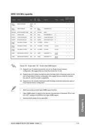
... you install the modules into slots A1 and B1 for the latest QVL. settings in the BIOS for the hyper DIMM support. • Visit the ASUS website for better compatibility. (4) Supports four (4) modules inserted into any slot as two pairs of Dual-channel memory configuration. •... socket support (Optional) 1 2 4 Mach MXD3U133316GQ 16GB DS - - Xtreme ( 4x 4GB ) - - • • • Mach Xtreme MXD3V13332GS 2GB SS Mach C2S46D30-D313 - - Single-sided DS - Chapter 1 ASUS SABERTOOTH Z97 MARK 1/USB 3.1 1-23 DDR3 1333 MHz capability Vendors Part No.
... you install the modules into slots A1 and B1 for the latest QVL. settings in the BIOS for the hyper DIMM support. • Visit the ASUS website for better compatibility. (4) Supports four (4) modules inserted into any slot as two pairs of Dual-channel memory configuration. •... socket support (Optional) 1 2 4 Mach MXD3U133316GQ 16GB DS - - Xtreme ( 4x 4GB ) - - • • • Mach Xtreme MXD3V13332GS 2GB SS Mach C2S46D30-D313 - - Single-sided DS - Chapter 1 ASUS SABERTOOTH Z97 MARK 1/USB 3.1 1-23 DDR3 1333 MHz capability Vendors Part No.
User Guide
Page 39
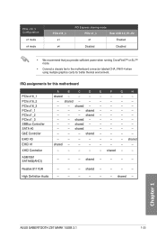
shared - - - - - - - shared - - - - - shared shared - - - - - - - - - - - - Realtek 8111GR - - - Chapter 1 ASUS SABERTOOTH Z97 MARK 1/USB 3.1 1-25 PCIe x16_3 Configuration x1 mode x4 mode PCIe x16_3 x1 x4 PCI Express sharing mode PCIe x1_3 Rear USB 3.0_E1~E2 x1 Enabled Disabled Disabled • We recommend that you provide sufficient power when running CrossFireX™ or SLI™ mode. • Connect a chassis...
shared - - - - - - - shared - - - - - shared shared - - - - - - - - - - - - Realtek 8111GR - - - Chapter 1 ASUS SABERTOOTH Z97 MARK 1/USB 3.1 1-25 PCIe x16_3 Configuration x1 mode x4 mode PCIe x16_3 x1 x4 PCI Express sharing mode PCIe x1_3 Rear USB 3.0_E1~E2 x1 Enabled Disabled Disabled • We recommend that you provide sufficient power when running CrossFireX™ or SLI™ mode. • Connect a chassis...
User Guide
Page 41
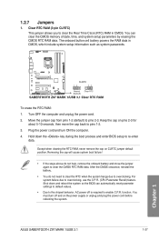
... the steps above do not need to clear the RTC when the system hangs due to re-enter data. For system failure due to pins 2-3. ASUS SABERTOOTH Z97 MARK 1/USB 3.1 1-27 Chapter 1 To erase the RTC RAM: 1. Shut down the key during the boot process and enter BIOS setup to overclocking. function. Except when clearing...
... the steps above do not need to clear the RTC when the system hangs due to re-enter data. For system failure due to pins 2-3. ASUS SABERTOOTH Z97 MARK 1/USB 3.1 1-27 Chapter 1 To erase the RTC RAM: 1. Shut down the key during the boot process and enter BIOS setup to overclocking. function. Except when clearing...
User Guide
Page 43
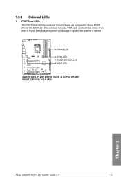
Chapter 1 ASUS SABERTOOTH Z97 MARK 1/USB 3.1 1-29 POST State LEDs The POST State LEDs provide the status of these key components during POST (Power-On-Self Test): CPU, memory modules, VGA card, and hard disk drives. 1.2.8 Onboard LEDs 1. If an error is found, the critical component's LED stays lit up until the problem is solved.
Chapter 1 ASUS SABERTOOTH Z97 MARK 1/USB 3.1 1-29 POST State LEDs The POST State LEDs provide the status of these key components during POST (Power-On-Self Test): CPU, memory modules, VGA card, and hard disk drives. 1.2.8 Onboard LEDs 1. If an error is found, the critical component's LED stays lit up until the problem is solved.
User Guide
Page 45
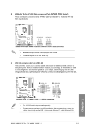
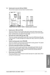
ASUS SABERTOOTH Z97 MARK 1/USB 3.1 1-31 Chapter 1 • The USB 3.0 module is purchased separately. • These connectors are for additional USB 3.0 front or rear panel ports. ASMedia® Serial ATA 6.0 Gb/s connectors (7-pin SATA6G_E1-E2 [beige]) These connectors connect to Serial ATA ... Gb/s hard disk drives via Serial ATA 6.0 Gb/s signal cables. • ASMedia storage controller can enjoy all the benefits of USB 3.0 including faster data transfer speeds of up to 5Gbps, faster charging time for USBchargeable devices, optimized power efficiency, and backward compatibility with...
ASUS SABERTOOTH Z97 MARK 1/USB 3.1 1-31 Chapter 1 • The USB 3.0 module is purchased separately. • These connectors are for additional USB 3.0 front or rear panel ports. ASMedia® Serial ATA 6.0 Gb/s connectors (7-pin SATA6G_E1-E2 [beige]) These connectors connect to Serial ATA ... Gb/s hard disk drives via Serial ATA 6.0 Gb/s signal cables. • ASMedia storage controller can enjoy all the benefits of USB 3.0 including faster data transfer speeds of up to 5Gbps, faster charging time for USBchargeable devices, optimized power efficiency, and backward compatibility with...
User Guide
Page 47
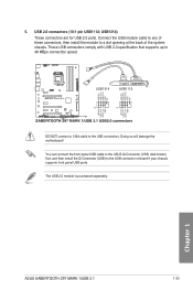
... NOT connect a 1394 cable to the USB connector onboard if your chassis supports front panel USB ports. Chapter 1 ASUS SABERTOOTH Z97 MARK 1/USB 3.1 1-33 USB1314) These connectors are for USB 2.0 ports. Doing so will damage the motherboard! 5. The USB 2.0 module is purchased separately. You can connect the front panel USB cable to the ASUS Q-Connector (USB, dark brown) first, and then install...
... NOT connect a 1394 cable to the USB connector onboard if your chassis supports front panel USB ports. Chapter 1 ASUS SABERTOOTH Z97 MARK 1/USB 3.1 1-33 USB1314) These connectors are for USB 2.0 ports. Doing so will damage the motherboard! 5. The USB 2.0 module is purchased separately. You can connect the front panel USB cable to the ASUS Q-Connector (USB, dark brown) first, and then install...
User Guide
Page 49
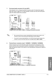
Thermal Sensor connectors (2-pin T_SENSOR1; Chapter 1 ASUS SABERTOOTH Z97 MARK 1/USB 3.1 1-35 7. Connect one end of the front panel audio I /O module that you connect a high-definition front panel audio module to this connector to avail of ...
Thermal Sensor connectors (2-pin T_SENSOR1; Chapter 1 ASUS SABERTOOTH Z97 MARK 1/USB 3.1 1-35 7. Connect one end of the front panel audio I /O module that you connect a high-definition front panel audio module to this connector to avail of ...
User Guide
Page 51
... lights up when you to the HDD. • System warning speaker (4-pin SPEAKER) This 4-pin connector is for the chassis-mounted system warning speaker. 10. ASUS SABERTOOTH Z97 MARK 1/USB 3.1 1-37 Chapter 1
... lights up when you to the HDD. • System warning speaker (4-pin SPEAKER) This 4-pin connector is for the chassis-mounted system warning speaker. 10. ASUS SABERTOOTH Z97 MARK 1/USB 3.1 1-37 Chapter 1
User Guide
Page 53
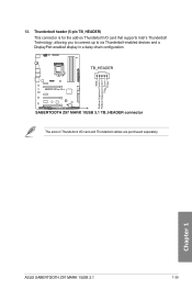
Chapter 1 ASUS SABERTOOTH Z97 MARK 1/USB 3.1 1-39 Thunderbolt header (5-pin TB_HEADER) This connector is for the add-on Thunderbolt I /O card that supports Intel's Thunderbolt Technology, allowing you to connect up to six Thunderbolt-enabled devices and a DisplayPort-enabled display in a daisy-chain configuration. 13. The add-on Thunderbolt I /O card and Thunderbolt cables are purchased separately.
Chapter 1 ASUS SABERTOOTH Z97 MARK 1/USB 3.1 1-39 Thunderbolt header (5-pin TB_HEADER) This connector is for the add-on Thunderbolt I /O card that supports Intel's Thunderbolt Technology, allowing you to connect up to six Thunderbolt-enabled devices and a DisplayPort-enabled display in a daisy-chain configuration. 13. The add-on Thunderbolt I /O card and Thunderbolt cables are purchased separately.
User Guide
Page 54
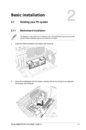
Chapter 2 ASUS SABERTOOTH Z97 MARK 1/USB 3.1 2-1 Install the ASUS Q-Shield to the chassis' rear I /O panel. 2. The motherboard layout may vary with models, but the installation steps are the same for reference only. Place the motherboard into the chassis, ensuring that its rear I/O ports are aligned to the chassis rear I /O panel. Chapter 2: Basic installation Basic installation 2.1 Building your PC system 2 2.1.1 Motherboard installation The diagrams in this section are for all models. 1.
Chapter 2 ASUS SABERTOOTH Z97 MARK 1/USB 3.1 2-1 Install the ASUS Q-Shield to the chassis' rear I /O panel. 2. The motherboard layout may vary with models, but the installation steps are the same for reference only. Place the motherboard into the chassis, ensuring that its rear I/O ports are aligned to the chassis rear I /O panel. Chapter 2: Basic installation Basic installation 2.1 Building your PC system 2 2.1.1 Motherboard installation The diagrams in this section are for all models. 1.
User Guide
Page 56
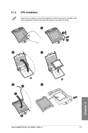
2.1.2 CPU installation Ensure that you install the correct CPU designed for LGA1155 and LGA1156 sockets on the LGA1150 socket. Chapter 2 ASUS SABERTOOTH Z97 MARK 1/USB 3.1 2-3 DO NOT install a CPU designed for LGA1150 socket only.
2.1.2 CPU installation Ensure that you install the correct CPU designed for LGA1155 and LGA1156 sockets on the LGA1150 socket. Chapter 2 ASUS SABERTOOTH Z97 MARK 1/USB 3.1 2-3 DO NOT install a CPU designed for LGA1150 socket only.
User Guide
Page 58
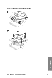
To uninstall the CPU heatsink and fan assembly Chapter 2 ASUS SABERTOOTH Z97 MARK 1/USB 3.1 2-5
To uninstall the CPU heatsink and fan assembly Chapter 2 ASUS SABERTOOTH Z97 MARK 1/USB 3.1 2-5


