User Guide
Page 4
... options 3.1 Installing friction rail kit items 3-2 3.1.1 Attaching the fixing latches to the server 3-2 3.1.2 Attaching the rack rails 3-3 3.1.3 Mounting the server to the rack 3-4 Chapter 4: Motherboard information 4.1 Motherboard layouts 4-2 4.2 Jumpers 4-4 4.3 Internal connectors 4-9 Chapter 5: BIOS setup 5.1 Managing and updating your BIOS 5-2 5.1.1 AFUDOS utility 5-2 5.1.2 ASUS CrashFree BIOS 3 utility 5-4 5.2 BIOS setup program 5-5 5.2.1 BIOS menu screen 5-6 5.2.2 Menu bar...
... options 3.1 Installing friction rail kit items 3-2 3.1.1 Attaching the fixing latches to the server 3-2 3.1.2 Attaching the rack rails 3-3 3.1.3 Mounting the server to the rack 3-4 Chapter 4: Motherboard information 4.1 Motherboard layouts 4-2 4.2 Jumpers 4-4 4.3 Internal connectors 4-9 Chapter 5: BIOS setup 5.1 Managing and updating your BIOS 5-2 5.1.1 AFUDOS utility 5-2 5.1.2 ASUS CrashFree BIOS 3 utility 5-4 5.2 BIOS setup program 5-5 5.2.1 BIOS menu screen 5-6 5.2.2 Menu bar...
User Guide
Page 5
... 5-22 5.4.6 Power On Configuration 5-23 5.4.7 Event Log Configuration 5-24 5.4.8 Hardware Monitor 5-24 5.4.9 Configure I/O Virtualization Parameters 5-25 5.4.10 PCI Express Configuration 5-26 5.4.11 ACPI Configuration 5-26 5.5 Server menu 5-28 5.6 Boot menu 5-30 5.6.1 Boot Device Priority 5-30 5.6.2 Boot Settings Configuration 5-31 5.6.3 Security 5-32 5.7 Exit menu 5-34 Chapter 6: RAID configuration 6.1 Setting up RAID 6-2 6.1.1 RAID...
... 5-22 5.4.6 Power On Configuration 5-23 5.4.7 Event Log Configuration 5-24 5.4.8 Hardware Monitor 5-24 5.4.9 Configure I/O Virtualization Parameters 5-25 5.4.10 PCI Express Configuration 5-26 5.4.11 ACPI Configuration 5-26 5.5 Server menu 5-28 5.6 Boot menu 5-30 5.6.1 Boot Device Priority 5-30 5.6.2 Boot Settings Configuration 5-31 5.6.3 Security 5-32 5.7 Exit menu 5-34 Chapter 6: RAID configuration 6.1 Setting up RAID 6-2 6.1.1 RAID...
User Guide
Page 8
... sockets and circuitry. • Avoid dust, humidity, and temperature extremes. Place the server on this server must be conducted by certified or experienced engineers. • Before operating the server, carefully read all cables are correctly connected and the power cables are connected. Dispose ...battery is incorrectly replaced. Use the power cable with the server package. • Before using the server, ensure all the manuals included with a properly grounded electrical outlet to avoid electrical shock. This server system is equipped with the same or equivalent type recommended...
... sockets and circuitry. • Avoid dust, humidity, and temperature extremes. Place the server on this server must be conducted by certified or experienced engineers. • Before operating the server, carefully read all cables are correctly connected and the power cables are connected. Dispose ...battery is incorrectly replaced. Use the power cable with the server package. • Before using the server, ensure all the manuals included with a properly grounded electrical outlet to avoid electrical shock. This server system is equipped with the same or equivalent type recommended...

User Guide
Page 9
... intended for different system components. Chapter 3: Installation options This chapter describes how to enable proper reuse of configuring a server. This chapter includes the motherboard layout, jumper settings, and connector locations. 5. Chapter 5: BIOS setup This chapter tells... chapter provides instructions for installing the necessary drivers for system integrators, and experienced users with the server. Check local regulations for disposal of the server, including sections on front panel and rear panel specifications. 2. Chapter 1: Product Introduction This chapter...
... intended for different system components. Chapter 3: Installation options This chapter describes how to enable proper reuse of configuring a server. This chapter includes the motherboard layout, jumper settings, and connector locations. 5. Chapter 5: BIOS setup This chapter tells... chapter provides instructions for installing the necessary drivers for system integrators, and experienced users with the server. Check local regulations for disposal of the server, including sections on front panel and rear panel specifications. 2. Chapter 1: Product Introduction This chapter...

User Guide
Page 10
...Typography Bold text Indicates a menu or an item to set up and use the proprietary ASUS server management utility. 2. ASUS Server Web-based Management (ASWM) user guide This manual tells how to select. ASUS websites The ASUS websites worldwide provide updated information for product and software updates. 1. IMPORTANT: Instructions that you... means that you perform certain tasks properly, take note of the following sources for additional information, and for all ASUS hardware and software products. Conventions To ensure that you must press the enclosed key.
...Typography Bold text Indicates a menu or an item to set up and use the proprietary ASUS server management utility. 2. ASUS Server Web-based Management (ASWM) user guide This manual tells how to select. ASUS websites The ASUS websites worldwide provide updated information for product and software updates. 1. IMPORTANT: Instructions that you... means that you perform certain tasks properly, take note of the following sources for additional information, and for all ASUS hardware and software products. Conventions To ensure that you must press the enclosed key.

User Guide
Page 12
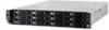
1.1 System package contents Check your system package for the following items. Model Name Chassis RS720-E6/RS12 ASUS R20C 2U Rackmount Chassis Motherboard ASUS Z8PE-D18 Server Board Component 1 x 770W Redundant Power Supply 1 x SATAII/SAS HDD Backplane (BP12LX-R20A) 12 x hot-swap HDD trays 1 x Front I/O Board (LED board, FPB-R20A) 1 x Front I/O Board (...
1.1 System package contents Check your system package for the following items. Model Name Chassis RS720-E6/RS12 ASUS R20C 2U Rackmount Chassis Motherboard ASUS Z8PE-D18 Server Board Component 1 x 770W Redundant Power Supply 1 x SATAII/SAS HDD Backplane (BP12LX-R20A) 12 x hot-swap HDD trays 1 x Front I/O Board (LED board, FPB-R20A) 1 x Front I/O Board (...

User Guide
Page 13
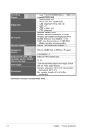
... 1: PCI-E x8 (G1 x4 link) (Auto disabled if PIKE slot is installed) 4 x Hot-swap 3.5" SATAII HDD Bays (continued on the next page) ASUS RS720-E6/RS12 1-3 Supports software RAID 0, 1, 5 & 10 LSI MegaRAID (for storage enhancement Intel® ICH10R: - 6 x SATA2 300MB/s ports - Slot 5: PCI-E ...1.3 System specifications The ASUS RS720-E6/RS12 is occupied) - Slot 3: PCI-E x16 (G2 x16 link) (Auto switch to 48GB (UDIMM) DDR3 1333 / 1066 / 800 Reg DIMM / Unbuffered DIMM with EM64T technology, plus other latest technologies through the chipsets onboard. The server supports Intel® ...
... 1: PCI-E x8 (G1 x4 link) (Auto disabled if PIKE slot is installed) 4 x Hot-swap 3.5" SATAII HDD Bays (continued on the next page) ASUS RS720-E6/RS12 1-3 Supports software RAID 0, 1, 5 & 10 LSI MegaRAID (for storage enhancement Intel® ICH10R: - 6 x SATA2 300MB/s ports - Slot 5: PCI-E ...1.3 System specifications The ASUS RS720-E6/RS12 is occupied) - Slot 3: PCI-E x16 (G2 x16 link) (Auto switch to 48GB (UDIMM) DDR3 1333 / 1066 / 800 Reg DIMM / Unbuffered DIMM with EM64T technology, plus other latest technologies through the chipsets onboard. The server supports Intel® ...
User Guide
Page 14
condensing) *Specifications are subject to change without any notice) Optional CA eTrust Anti-virus Software CD Optional ASMB4-iKVM for KVM-over-IP support ASUS ASWM 2.0 615mm x 444mm x 87mm (2U) 25 Kg 770W (80+) 1+1 Redundant Power Supply (Default with one Power Supply Module) ...ASMB4-iKVM) 4 x USB 2.0 ports (Front x 2, Rear x 2) 1 x VGA port 1 x PS/2 keyboard port 1 x PS/2 mouse port Windows® Server 2008 R2 Windows® Server 2008 Enterprise 32 / 64-bit Windows® Server 2003 R2 Enterprise 32 / 64-bit RedHat® Enterprise Linux AS5.0 32 / 64-bit SuSE® Linux Enterprise...
condensing) *Specifications are subject to change without any notice) Optional CA eTrust Anti-virus Software CD Optional ASMB4-iKVM for KVM-over-IP support ASUS ASWM 2.0 615mm x 444mm x 87mm (2U) 25 Kg 770W (80+) 1+1 Redundant Power Supply (Default with one Power Supply Module) ...ASMB4-iKVM) 4 x USB 2.0 ports (Front x 2, Rear x 2) 1 x VGA port 1 x PS/2 keyboard port 1 x PS/2 mouse port Windows® Server 2008 R2 Windows® Server 2008 Enterprise 32 / 64-bit Windows® Server 2003 R2 Enterprise 32 / 64-bit RedHat® Enterprise Linux AS5.0 32 / 64-bit SuSE® Linux Enterprise...

User Guide
Page 15
.... ASUS RS720-E6/RS12 1-5 The middle part includes the I/O shield with easily accessible features. The power and reset buttons, LED indicators, optical drive, and two USB ports are located on the rear panel if motherboard is not present. • *The port is for ASUS ASMB4-iKVM controller card only. 1.4 Front panel features The barebone server displays...
.... ASUS RS720-E6/RS12 1-5 The middle part includes the I/O shield with easily accessible features. The power and reset buttons, LED indicators, optical drive, and two USB ports are located on the rear panel if motherboard is not present. • *The port is for ASUS ASMB4-iKVM controller card only. 1.4 Front panel features The barebone server displays...
User Guide
Page 16
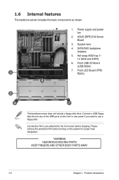
... remove the protection film before turning on the front or rear panel if you need to the front cover before shipping. ASUS Z8PE-D18 Server Board 3. Front LED Board (FPBR20A) 4 5 6 7 The barebone server does not include a floppy disk drive. A protection film is pre-attached to use a floppy disk. Front USB I/O Board (USB-R20A... on the system for proper heat dissipation. *WARNING HAZARDOUS MOVING PARTS KEEP FINGERS AND OTHER BODY PARTS AWAY 1-6 Chapter 1: Product introduction 1.6 Internal features The barebone server includes the basic components as shown. 2 3 1.
... remove the protection film before turning on the front or rear panel if you need to the front cover before shipping. ASUS Z8PE-D18 Server Board 3. Front LED Board (FPBR20A) 4 5 6 7 The barebone server does not include a floppy disk drive. A protection film is pre-attached to use a floppy disk. Front USB I/O Board (USB-R20A... on the system for proper heat dissipation. *WARNING HAZARDOUS MOVING PARTS KEEP FINGERS AND OTHER BODY PARTS AWAY 1-6 Chapter 1: Product introduction 1.6 Internal features The barebone server includes the basic components as shown. 2 3 1.
User Guide
Page 34
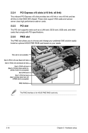
2.5.4 PCI Express x16 slots (x16 link; This slot is for ASUS PIKE RAID card only. 2-16 Chapter 2: Hardware setup Install an optional ASUS PIKE RAID card based on cards. 2.5.5 PCI slot The PCI slot supports cards such as a LAN card, SCSI card, USB card, and other cards that ... slot (Gen2 x8 link) Slot 3: PCI-E x16 slot (Gen2 x16 link) (Auto switch to Intel 5520 IOH chipset. These slots support VGA cards and various server class high performance add-on your preferred SAS solution easily.
2.5.4 PCI Express x16 slots (x16 link; This slot is for ASUS PIKE RAID card only. 2-16 Chapter 2: Hardware setup Install an optional ASUS PIKE RAID card based on cards. 2.5.5 PCI slot The PCI slot supports cards such as a LAN card, SCSI card, USB card, and other cards that ... slot (Gen2 x8 link) Slot 3: PCI-E x16 slot (Gen2 x16 link) (Auto switch to Intel 5520 IOH chipset. These slots support VGA cards and various server class high performance add-on your preferred SAS solution easily.
User Guide
Page 41
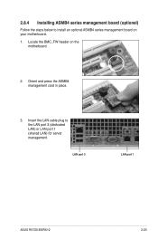
LAN port 3 LAN port 1 ASUS RS720-E6/RS12 2-23 Orient and press the ASMB4 management card in place. 3. Locate the BMC_FW header on your motherboard. 1. Insert the LAN cable plug to install an optional ASMB4 series management board on the motherboard. 2. 2.8.4 Installing ASMB4 series management board (optional) Follow the steps below to the LAN port 3 (dedicated LAN) or LAN port 1 (shared LAN) for server management.
LAN port 3 LAN port 1 ASUS RS720-E6/RS12 2-23 Orient and press the ASMB4 management card in place. 3. Locate the BMC_FW header on your motherboard. 1. Insert the LAN cable plug to install an optional ASMB4 series management board on the motherboard. 2. 2.8.4 Installing ASMB4 series management board (optional) Follow the steps below to the LAN port 3 (dedicated LAN) or LAN port 1 (shared LAN) for server management.

User Guide
Page 43
Installation options Chapter 3 This chapter describes how to install the optional components and devices into the barebone server. ASUS RS720-E6/RS12 2-
Installation options Chapter 3 This chapter describes how to install the optional components and devices into the barebone server. ASUS RS720-E6/RS12 2-
User Guide
Page 44
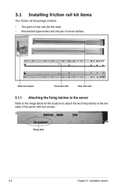
3.1 Installing friction rail kit items Your friction rail kit package contains: • Two pairs of rack rails (for the rack) • Nut-and-bolt type screws and one pair of server latches Nuts and screws Front rack rails Rear rack rails 3.1.1 Attaching the fixing latches to the server Refer to the image below for the locations to attach the two fixing latches to the two sides of the server with four screws. Fixing latch 3-2 Chapter 3: Installation options
3.1 Installing friction rail kit items Your friction rail kit package contains: • Two pairs of rack rails (for the rack) • Nut-and-bolt type screws and one pair of server latches Nuts and screws Front rack rails Rear rack rails 3.1.1 Attaching the fixing latches to the server Refer to the image below for the locations to attach the two fixing latches to the two sides of the server with four screws. Fixing latch 3-2 Chapter 3: Installation options
User Guide
Page 45
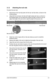
... the rack space. 7. Repeat steps 6 to 9 to the front of the rack rail goes to assemble and attach the rack rail on the other 8 side. 9 8 9 7 ASUS RS720-E6/RS12 3-3 Adjust the rack rail to the 2U space on the rack where you want to meet the depth of the rail with eight screws and... ensure that you secure in step 2, as shown in the right figure. 10. Secure the rear end of the server rack. Select two units of the rack rails to install the barebone server. 4. Do not secure the screws too tight so that it fits the rack. 6. Rear rail rack Front rail rack...
... the rack space. 7. Repeat steps 6 to 9 to the front of the rack rail goes to assemble and attach the rack rail on the other 8 side. 9 8 9 7 ASUS RS720-E6/RS12 3-3 Adjust the rack rail to the 2U space on the rack where you want to meet the depth of the rail with eight screws and... ensure that you secure in step 2, as shown in the right figure. 10. Secure the rear end of the server rack. Select two units of the rack rails to install the barebone server. 4. Do not secure the screws too tight so that it fits the rack. 6. Rear rail rack Front rail rack...
User Guide
Page 46
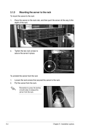
Loosen the rack screws that secured the server to secure the server in place. To uninstall the server from the rack. Pull the server from the rack 1. Place the server on both sides to release the server from the rack. 3-4 Chapter 3: Installation options Remember to press the latches on the rack rails, and then push the server all the way to the rack 1. Tighten the two rack screws to the rack. 2. 3.1.3 Mounting the server to the rack To mount the server to the depth of the rack. 2.
Loosen the rack screws that secured the server to secure the server in place. To uninstall the server from the rack. Pull the server from the rack 1. Place the server on both sides to release the server from the rack. 3-4 Chapter 3: Installation options Remember to press the latches on the rack rails, and then push the server all the way to the rack 1. Tighten the two rack screws to the rack. 2. 3.1.3 Mounting the server to the rack To mount the server to the depth of the rack. 2.
User Guide
Page 60
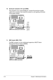
O_RXD2 O_DTR2 O_DSR2 O_CTS2 10. Serial port connector (10-1 pin COM2) This connector is for a serial (COM) port. Connect the serial port module cable to this connector, then install the module to a slot opening at the back of the system chassis. 11. BMC header (BMC_FW1) The BMC connector on the motherboard supports an ASUS® Server Management Board 4 Series (ASMB4). O_DCD2 O_TXD2 GND O_RTS2 O_RI2 4-14 Chapter 4: Motherboard information
O_RXD2 O_DTR2 O_DSR2 O_CTS2 10. Serial port connector (10-1 pin COM2) This connector is for a serial (COM) port. Connect the serial port module cable to this connector, then install the module to a slot opening at the back of the system chassis. 11. BMC header (BMC_FW1) The BMC connector on the motherboard supports an ASUS® Server Management Board 4 Series (ASMB4). O_DCD2 O_TXD2 GND O_RTS2 O_RI2 4-14 Chapter 4: Motherboard information
User Guide
Page 70
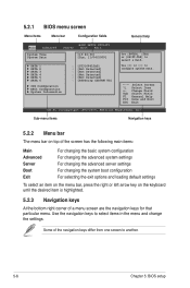
... on top of the screen has the following main items: Main Advanced Server Boot Exit For changing the basic system configuration For changing the advanced system settings For changing the advanced server settings For changing the system boot configuration For selecting the exit options and... menu. Use the navigation keys to select a field. 5.2.1 BIOS menu screen Menu items Menu bar Configuration fields General help Main Advanced BIOS SETUP UTILITY Server Boot Exit System Time [13:44:30] System Date [Tue, 11/04/2009] SATA 1 SATA 2 SATA 3 SATA 4 SATA 5 SATA 6...
... on top of the screen has the following main items: Main Advanced Server Boot Exit For changing the basic system configuration For changing the advanced system settings For changing the advanced server settings For changing the system boot configuration For selecting the exit options and... menu. Use the navigation keys to select a field. 5.2.1 BIOS menu screen Menu items Menu bar Configuration fields General help Main Advanced BIOS SETUP UTILITY Server Boot Exit System Time [13:44:30] System Date [Tue, 11/04/2009] SATA 1 SATA 2 SATA 3 SATA 4 SATA 5 SATA 6...
User Guide
Page 72
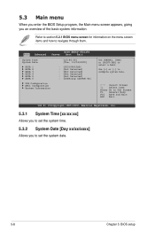
Main Advanced BIOS SETUP UTILITY Server Boot Exit System Time [13:44:30] System Date [Tue, 11/04/2009] SATA 1 SATA 2 SATA 3 SATA 4 SATA 5 SATA 6 : [ST3160812AS] : [Not Detected] : [Not Detected] : [Not ...
Main Advanced BIOS SETUP UTILITY Server Boot Exit System Time [13:44:30] System Date [Tue, 11/04/2009] SATA 1 SATA 2 SATA 3 SATA 4 SATA 5 SATA 6 : [ST3160812AS] : [Not Detected] : [Not Detected] : [Not ...

User Guide
Page 77
Main Advanced Server BIOS SETUP UTILITY Boot Exit CPU Configuration Chipset Configuration Legacy Device Configuration USB Configuration PCIPnP Configuration APM Configuration Event Log Configuration Hardware Monitor I/O Virtualization PCI ... [Enabled] C State package limit setting [Auto] C1 Auto Demotion [Enabled] C3 Auto Demotion [Enabled] ACPI T State [Enabled] v02.61 (C)Copyright 1985-2009, American Megatrends, Inc. ASUS RS720-E6/RS12 5-13
Main Advanced Server BIOS SETUP UTILITY Boot Exit CPU Configuration Chipset Configuration Legacy Device Configuration USB Configuration PCIPnP Configuration APM Configuration Event Log Configuration Hardware Monitor I/O Virtualization PCI ... [Enabled] C State package limit setting [Auto] C1 Auto Demotion [Enabled] C3 Auto Demotion [Enabled] ACPI T State [Enabled] v02.61 (C)Copyright 1985-2009, American Megatrends, Inc. ASUS RS720-E6/RS12 5-13
