User Guide
Page 3
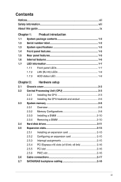
... specifications 1-3 1.4 Front panel features 1-5 1.5 Rear panel features 1-5 1.6 Internal features 1-6 1.7 LED information 1-7 1.7.1 Front panel LEDs 1-7 1.7.2 LAN (RJ-45) LEDs 1-8 1.7.3 HDD status LED 1-8 Chapter 2: Hardware setup 2.1 Chassis cover 2-2 2.2 Central Processing Unit (CPU 2-3 2.2.1 Installing the CPU 2-3 2.2.2 Installing the CPU heatsink and airduct 2-6 2.3 System memory 2-8 2.3.1 Overview 2-8 2.3.2 Memory Configurations 2-8 2.3.3 Installing a DIMM 2-10 2.3.4 Removing a DIMM 2-10 2.4 Hard...
... specifications 1-3 1.4 Front panel features 1-5 1.5 Rear panel features 1-5 1.6 Internal features 1-6 1.7 LED information 1-7 1.7.1 Front panel LEDs 1-7 1.7.2 LAN (RJ-45) LEDs 1-8 1.7.3 HDD status LED 1-8 Chapter 2: Hardware setup 2.1 Chassis cover 2-2 2.2 Central Processing Unit (CPU 2-3 2.2.1 Installing the CPU 2-3 2.2.2 Installing the CPU heatsink and airduct 2-6 2.3 System memory 2-8 2.3.1 Overview 2-8 2.3.2 Memory Configurations 2-8 2.3.3 Installing a DIMM 2-10 2.3.4 Removing a DIMM 2-10 2.4 Hard...

User Guide
Page 15
Refer to section 1.7.1 Front panel LEDs for ASUS ASMB4-iKVM controller card only. ASUS RS720-E6/RS12 1-5 USB ports HDD 1 (SAS) HDD 2 (SAS) HDD 3 (SAS) HDD 4 (SAS) Power button Front panel LEDs Location switch HDD 5 (SAS) HDD 6 (SAS) HDD 7 (SAS) HDD 8 (SAS) ... LAN port 2 LAN port 1 VGA port Serial port USB ports LAN port 3* PS/2 keyboard port PS/2 mouse port Power cord connector Redundant power supply dummy cover • The ports for the PS/2 keyboard, PS/2 mouse, serial port, USB, VGA, and Gigabit LAN do not appear on the front panel. The middle...
Refer to section 1.7.1 Front panel LEDs for ASUS ASMB4-iKVM controller card only. ASUS RS720-E6/RS12 1-5 USB ports HDD 1 (SAS) HDD 2 (SAS) HDD 3 (SAS) HDD 4 (SAS) Power button Front panel LEDs Location switch HDD 5 (SAS) HDD 6 (SAS) HDD 7 (SAS) HDD 8 (SAS) ... LAN port 2 LAN port 1 VGA port Serial port USB ports LAN port 3* PS/2 keyboard port PS/2 mouse port Power cord connector Redundant power supply dummy cover • The ports for the PS/2 keyboard, PS/2 mouse, serial port, USB, VGA, and Gigabit LAN do not appear on the front panel. The middle...
User Guide
Page 16
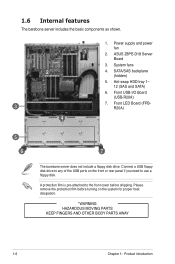
...(SAS and SATA) 6. Please remove the protection film before turning on the front or rear panel if you need to the front cover before shipping. A protection film is pre-attached to use a floppy disk. 1.6 Internal features The barebone server includes the basic components ...as shown. 2 3 1. System fans 4. Front USB I/O Board (USB-R20A) 7. ASUS Z8PE-D18 Server Board 3. Front LED Board (FPBR20A) 4 5 6 7 The barebone server does not include a floppy disk drive. Power supply and power...
...(SAS and SATA) 6. Please remove the protection film before turning on the front or rear panel if you need to the front cover before shipping. A protection film is pre-attached to use a floppy disk. 1.6 Internal features The barebone server includes the basic components ...as shown. 2 3 1. System fans 4. Front USB I/O Board (USB-R20A) 7. ASUS Z8PE-D18 Server Board 3. Front LED Board (FPBR20A) 4 5 6 7 The barebone server does not include a floppy disk drive. Power supply and power...
User Guide
Page 20
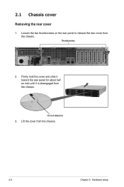
Lift the cover from the chassis. Loosen the two thumbscrews on the rear panel to release the rear cover from the chassis. 2-2 Chapter 2: Hardware setup Firmly hold the cover and slide it toward the rear panel for about half an inch until it is disengaged from the chassis. 1/2 inch distance 3. 2.1 Chassis cover Removing the rear cover 1. Thumbscrews 2.
Lift the cover from the chassis. Loosen the two thumbscrews on the rear panel to release the rear cover from the chassis. 2-2 Chapter 2: Hardware setup Firmly hold the cover and slide it toward the rear panel for about half an inch until it is disengaged from the chassis. 1/2 inch distance 3. 2.1 Chassis cover Removing the rear cover 1. Thumbscrews 2.
User Guide
Page 21
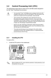
Contact your left. ASUS RS720-E6/RS12 2-3 Before installing the CPU, ensure that the PnP cap is on the LGA1366 socket. • The product warranty does not cover damage to the PnP cap/socket contacts/motherboard components. 2.2 Central Processing Unit (CPU) The motherboard comes with two surface ... your retailer immediately if the PnP cap is shipment/transit-related. • Keep the cap after installing the motherboard. ASUS will process Return Merchandise Authorization (RMA) requests only if the motherboard comes with installation instructions for the CPU and heatsink...
Contact your left. ASUS RS720-E6/RS12 2-3 Before installing the CPU, ensure that the PnP cap is on the LGA1366 socket. • The product warranty does not cover damage to the PnP cap/socket contacts/motherboard components. 2.2 Central Processing Unit (CPU) The motherboard comes with two surface ... your retailer immediately if the PnP cap is shipment/transit-related. • Keep the cap after installing the motherboard. ASUS will process Return Merchandise Authorization (RMA) requests only if the motherboard comes with installation instructions for the CPU and heatsink...
User Guide
Page 31
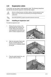
...cover opposite the slot where you physical injury and damage motherboard components. Place the metal bracket lock, and secure it aside. Failure to do so may need to install expansion cards. Ensure to unplug the power cord before adding or removing expansion cards. Align the card golden fingers with two screws. ASUS RS720-E6/RS12... the metal bracket lock, and then set it with the slot, and then press firmly until the card is completely seated on the slot. 3. ASUS RS720-E6/RS12 2-13 2.5 Expansion slots In the future, you may cause you wish to install an expansion card. 2.
...cover opposite the slot where you physical injury and damage motherboard components. Place the metal bracket lock, and secure it aside. Failure to do so may need to install expansion cards. Ensure to unplug the power cord before adding or removing expansion cards. Align the card golden fingers with two screws. ASUS RS720-E6/RS12... the metal bracket lock, and then set it with the slot, and then press firmly until the card is completely seated on the slot. 3. ASUS RS720-E6/RS12 2-13 2.5 Expansion slots In the future, you may cause you wish to install an expansion card. 2.
User Guide
Page 38
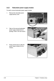
Take out the seocond redundant power supply module from its package. Firmly pull the lever to slide the power supply module into the chassis. 3. 2.8.2 Redundant power supply module To install a second redundant power supply module: 1. Slide it into the chassis. 2-20 Chapter 2: Hardware setup Remove the redundant power supply dummy cover. 2.
Take out the seocond redundant power supply module from its package. Firmly pull the lever to slide the power supply module into the chassis. 3. 2.8.2 Redundant power supply module To install a second redundant power supply module: 1. Slide it into the chassis. 2-20 Chapter 2: Hardware setup Remove the redundant power supply dummy cover. 2.

User Guide
Page 155
ASUS RS720-E6/RS12 7-25 Click an item to install. 7.5.4 Make disk menu The Make disk menu contains items to create the Intel ICH10R and LSI MegaRAID driver disks. 7.5.5 Contact information Click the Contact tab to display the ASUS contact information. You can also find this information on the inside front cover of this user guide. 7.5.3 Utilities menu The Utilities menu displays the software applications and utilities that the motherboard supports.
ASUS RS720-E6/RS12 7-25 Click an item to install. 7.5.4 Make disk menu The Make disk menu contains items to create the Intel ICH10R and LSI MegaRAID driver disks. 7.5.5 Contact information Click the Contact tab to display the ASUS contact information. You can also find this information on the inside front cover of this user guide. 7.5.3 Utilities menu The Utilities menu displays the software applications and utilities that the motherboard supports.