
User Guide
Page 11
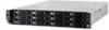
Product introduction Chapter 1 This chapter describes the general features of the chassis kit. It includes sections on front panel and rear panel specifications. ASUS RS720-E6/RS12 1-
Product introduction Chapter 1 This chapter describes the general features of the chassis kit. It includes sections on front panel and rear panel specifications. ASUS RS720-E6/RS12 1-

User Guide
Page 13
...SATAII HDD Bays (continued on the next page) ASUS RS720-E6/RS12 1-3 Slot 5: PCI-E x16 (G2 x16 link) 1 x PIKE slot for Windows only) - Supports software RAID 0, 1 & 10 Optional: ASUS PIKE 1068E 8-port SAS RAID card ASUS PIKE 1078 8-port SAS HW RAID card ASUS PIKE 6480 8-port SAS RAID card 8 x ... (RDIMM) Maximum up to x8 link if slot 4 is a server featuring the ASUS Z8PE-D18 server board. Supports software RAID 0, 1, 5 & 10 LSI MegaRAID (for Linux / Windows) - 1.3 System specifications The ASUS RS720-E6/RS12 is occupied) - Slot 2: PCI - The server supports Intel® LGA1366 Xeon&#...
...SATAII HDD Bays (continued on the next page) ASUS RS720-E6/RS12 1-3 Slot 5: PCI-E x16 (G2 x16 link) 1 x PIKE slot for Windows only) - Supports software RAID 0, 1 & 10 Optional: ASUS PIKE 1068E 8-port SAS RAID card ASUS PIKE 1078 8-port SAS HW RAID card ASUS PIKE 6480 8-port SAS RAID card 8 x ... (RDIMM) Maximum up to x8 link if slot 4 is a server featuring the ASUS Z8PE-D18 server board. Supports software RAID 0, 1, 5 & 10 LSI MegaRAID (for Linux / Windows) - 1.3 System specifications The ASUS RS720-E6/RS12 is occupied) - Slot 2: PCI - The server supports Intel® LGA1366 Xeon&#...

User Guide
Page 15
... panel includes the expansion slots, system power socket, and rear fans. Refer to section 1.7.1 Front panel LEDs for ASUS ASMB4-iKVM controller card only. The middle part includes the I/O shield with easily accessible features. ASUS RS720-E6/RS12 1-5 1.4 Front panel features The barebone server displays a simple yet stylish front panel with openings for the rear...
... panel includes the expansion slots, system power socket, and rear fans. Refer to section 1.7.1 Front panel LEDs for ASUS ASMB4-iKVM controller card only. The middle part includes the I/O shield with easily accessible features. ASUS RS720-E6/RS12 1-5 1.4 Front panel features The barebone server displays a simple yet stylish front panel with openings for the rear...

User Guide
Page 17
... LED Message LED Location LED LAN LEDs ON System power ON OFF No activity Blinking Read/write data into the HDD OFF System is present ASUS RS720-E6/RS12 1-7 Without ASMB4-iKVM installed: CPU over-heated ON 2. With ASMB4-iKVM installed: a hardware monitor event is indicated OFF Normal status ON Location switch is pressed...
... LED Message LED Location LED LAN LEDs ON System power ON OFF No activity Blinking Read/write data into the HDD OFF System is present ASUS RS720-E6/RS12 1-7 Without ASMB4-iKVM installed: CPU over-heated ON 2. With ASMB4-iKVM installed: a hardware monitor event is indicated OFF Normal status ON Location switch is pressed...
User Guide
Page 19
ASUS RS720-E6/RS12 2- Hardware setup Chapter 2 This chapter lists the hardware setup procedures that you have to perform when installing or removing system components.
ASUS RS720-E6/RS12 2- Hardware setup Chapter 2 This chapter lists the hardware setup procedures that you have to perform when installing or removing system components.
User Guide
Page 21
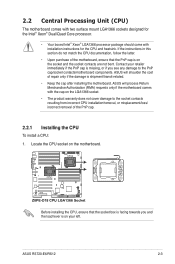
...to the socket contacts resulting from incorrect CPU installation/removal, or misplacement/loss/ incorrect removal of repair only if the damage is on the motherboard. ASUS will shoulder the cost of the PnP cap. 2.2.1 Installing the CPU To install a CPU: 1. 2.2 Central Processing Unit (CPU) The motherboard ... CPU and heatsink. Contact your left. Locate the CPU socket on the socket and the socket contacts are not bent. ASUS RS720-E6/RS12 2-3 Before installing the CPU, ensure that the PnP cap is shipment/transit-related. • Keep the cap after installing the motherboard.
...to the socket contacts resulting from incorrect CPU installation/removal, or misplacement/loss/ incorrect removal of repair only if the damage is on the motherboard. ASUS will shoulder the cost of the PnP cap. 2.2.1 Installing the CPU To install a CPU: 1. 2.2 Central Processing Unit (CPU) The motherboard ... CPU and heatsink. Contact your left. Locate the CPU socket on the socket and the socket contacts are not bent. ASUS RS720-E6/RS12 2-3 Before installing the CPU, ensure that the PnP cap is shipment/transit-related. • Keep the cap after installing the motherboard.

User Guide
Page 23
... gold triangle is spread in only one correct orientation. DO NOT eat the thermal Interface Material. If it off immediately and seek professional medical help. A ASUS RS720-E6/RS12 B 2-5 If so, skip this step. To prevent contaminating the paste, DO NOT spread the paste with your skin, ensure that you wash it gets into...
... gold triangle is spread in only one correct orientation. DO NOT eat the thermal Interface Material. If it off immediately and seek professional medical help. A ASUS RS720-E6/RS12 B 2-5 If so, skip this step. To prevent contaminating the paste, DO NOT spread the paste with your skin, ensure that you wash it gets into...
User Guide
Page 25
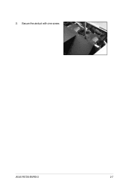
2. ASUS RS720-E6/RS12 2-7 Secure the airduct with one screw.
2. ASUS RS720-E6/RS12 2-7 Secure the airduct with one screw.
User Guide
Page 27
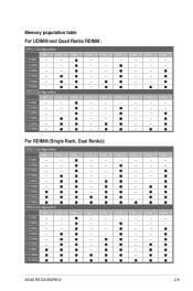
... -- -- -- -- -- 5 DIMMs -- -- -- -- 6 DIMMs -- -- -- 7 DIMMs -- -- 8 DIMMs 9 DIMMs CPU 2 Configuration DIMM_D3 DIMM_D2 DIMM_D1 DIMM_E3 DIMM_E2 DIMM_E1 DIMM_F3 DIMM_F2 DIMM_F1 1 DIMM -- -- -- -- -- -- -- -- 2 DIMMs -- -- -- -- -- -- -- 3 DIMMs -- -- -- -- -- -- 4 DIMMs -- -- -- -- -- 5 DIMMs -- -- -- -- 6 DIMMs -- -- -- 7 DIMMs -- -- 8 DIMMs -- 9 DIMMs ASUS RS720-E6/RS12 2-9 CPU 2 Configuration -- -- --
... -- -- -- -- -- 5 DIMMs -- -- -- -- 6 DIMMs -- -- -- 7 DIMMs -- -- 8 DIMMs 9 DIMMs CPU 2 Configuration DIMM_D3 DIMM_D2 DIMM_D1 DIMM_E3 DIMM_E2 DIMM_E1 DIMM_F3 DIMM_F2 DIMM_F1 1 DIMM -- -- -- -- -- -- -- -- 2 DIMMs -- -- -- -- -- -- -- 3 DIMMs -- -- -- -- -- -- 4 DIMMs -- -- -- -- -- 5 DIMMs -- -- -- -- 6 DIMMs -- -- -- 7 DIMMs -- -- 8 DIMMs -- 9 DIMMs ASUS RS720-E6/RS12 2-9 CPU 2 Configuration -- -- --
User Guide
Page 29
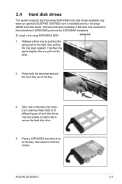
..., then pulling the tray lever outward. 2.4 Hard disk drives The system supports eight hot-swap SATAII/SAS hard disk drives (available only when an optional ASUS PIKE SAS RAID card is installed) and four hot-swap SATAII hard disk drives. Use two screws on each side to fit different types of... to secure the hard disk drive. 4. Release a drive tray by pushing the spring lock to the motherboard SATAII/SAS ports via the SATAII/SAS backplane. ASUS RS720-E6/RS12 2-11 The hard disk drive installed on the tray, then secure it with four screws.
..., then pulling the tray lever outward. 2.4 Hard disk drives The system supports eight hot-swap SATAII/SAS hard disk drives (available only when an optional ASUS PIKE SAS RAID card is installed) and four hot-swap SATAII hard disk drives. Use two screws on each side to fit different types of... to secure the hard disk drive. 4. Release a drive tray by pushing the spring lock to the motherboard SATAII/SAS ports via the SATAII/SAS backplane. ASUS RS720-E6/RS12 2-11 The hard disk drive installed on the tray, then secure it with four screws.
User Guide
Page 31
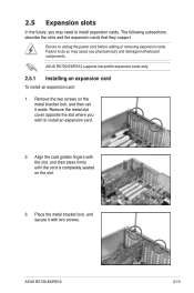
... expansion card. 2. Remove the metal slot cover opposite the slot where you physical injury and damage motherboard components. ASUS RS720-E6/RS12 supports low-profile expansion cards only. 2.5.1 Installing an expansion card To install an expansion card: 1. ASUS RS720-E6/RS12 2-13 2.5 Expansion slots In the future, you may cause you wish to install expansion cards. Remove the...
... expansion card. 2. Remove the metal slot cover opposite the slot where you physical injury and damage motherboard components. ASUS RS720-E6/RS12 supports low-profile expansion cards only. 2.5.1 Installing an expansion card To install an expansion card: 1. ASUS RS720-E6/RS12 2-13 2.5 Expansion slots In the future, you may cause you wish to install expansion cards. Remove the...
User Guide
Page 33
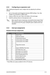
... an expansion card After installing the expansion card, configure the it by adjusting the software settings. 1. Install the software drivers for ISA or PCI devices. ASUS RS720-E6/RS12 2-15 When using PCI cards on BIOS setup. 2. See Chapter 5 for information on shared slots, ensure that the drivers support "Share IRQ" or that the...
... an expansion card After installing the expansion card, configure the it by adjusting the software settings. 1. Install the software drivers for ISA or PCI devices. ASUS RS720-E6/RS12 2-15 When using PCI cards on BIOS setup. 2. See Chapter 5 for information on shared slots, ensure that the drivers support "Share IRQ" or that the...

User Guide
Page 35
... motherboard) 4. SATA connectors (from motherboard to SATAII/SAS backplane board) 8. Auxiliary panel connector (from motherboard to front I /O board) 7. Panel connector (from motherboard to front I /O board) ASUS RS720-E6/RS12 2-17 SAS connectors (from motherboard to SATAII/SAS backplane board) 9. 2.6 Cable connections • The bundled system cables are pre-connected before shipment.
... motherboard) 4. SATA connectors (from motherboard to SATAII/SAS backplane board) 8. Auxiliary panel connector (from motherboard to front I /O board) 7. Panel connector (from motherboard to front I /O board) ASUS RS720-E6/RS12 2-17 SAS connectors (from motherboard to SATAII/SAS backplane board) 9. 2.6 Cable connections • The bundled system cables are pre-connected before shipment.

User Guide
Page 37
Repeat step 1 to 2 to release the system fan. 2. ASUS RS720-E6/RS12 2-19 Press inward to uninstall the other system fans. System fans 2. Lift the fan, then set aside. 3. Redundant power supply module (optional) 3. 2.8 Removable/...the system. Or you may need to remove previously installed system components when installing or removing system devices. ASUS PIKE RAID card (optional) 4. This section tells how to remove/install the following components: 1. ASUS ASMB4-iKVM (optional) Ensure that the system is turned off before removing any components. 2.8.1 System fans ...
Repeat step 1 to 2 to release the system fan. 2. ASUS RS720-E6/RS12 2-19 Press inward to uninstall the other system fans. System fans 2. Lift the fan, then set aside. 3. Redundant power supply module (optional) 3. 2.8 Removable/...the system. Or you may need to remove previously installed system components when installing or removing system devices. ASUS PIKE RAID card (optional) 4. This section tells how to remove/install the following components: 1. ASUS ASMB4-iKVM (optional) Ensure that the system is turned off before removing any components. 2.8.1 System fans ...
User Guide
Page 39
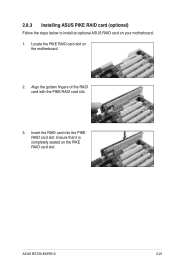
Align the golden fingers of the RAID card with the PIKE RAID card slot. 3. Ensure that it is completely seated on your motherboard. 1. ASUS RS720-E6/RS12 2-21 Insert the RAID card into the PIKE RAID card slot. 2.8.3 Installing ASUS PIKE RAID card (optional) Follow the steps below to install an optional ASUS RAID card on the PIKE RAID card slot. Locate the PIKE RAID card slot on the motherboard. 2.
Align the golden fingers of the RAID card with the PIKE RAID card slot. 3. Ensure that it is completely seated on your motherboard. 1. ASUS RS720-E6/RS12 2-21 Insert the RAID card into the PIKE RAID card slot. 2.8.3 Installing ASUS PIKE RAID card (optional) Follow the steps below to install an optional ASUS RAID card on the PIKE RAID card slot. Locate the PIKE RAID card slot on the motherboard. 2.
User Guide
Page 41
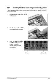
Insert the LAN cable plug to install an optional ASMB4 series management board on the motherboard. 2. LAN port 3 LAN port 1 ASUS RS720-E6/RS12 2-23 Orient and press the ASMB4 management card in place. 3. 2.8.4 Installing ASMB4 series management board (optional) Follow the steps below to the LAN port 3 (dedicated LAN) or LAN port 1 (shared LAN) for server management. Locate the BMC_FW header on your motherboard. 1.
Insert the LAN cable plug to install an optional ASMB4 series management board on the motherboard. 2. LAN port 3 LAN port 1 ASUS RS720-E6/RS12 2-23 Orient and press the ASMB4 management card in place. 3. 2.8.4 Installing ASMB4 series management board (optional) Follow the steps below to the LAN port 3 (dedicated LAN) or LAN port 1 (shared LAN) for server management. Locate the BMC_FW header on your motherboard. 1.

User Guide
Page 43
Installation options Chapter 3 This chapter describes how to install the optional components and devices into the barebone server. ASUS RS720-E6/RS12 2-
Installation options Chapter 3 This chapter describes how to install the optional components and devices into the barebone server. ASUS RS720-E6/RS12 2-
User Guide
Page 45
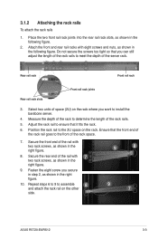
... Front rail rack joints Rear rail rack slots 3. Measure the depth of the rack to assemble and attach the rack rail on the other 8 side. 9 8 9 7 ASUS RS720-E6/RS12 3-3 Repeat steps 6 to 9 to determine the length of the rack rails to the 2U space on the rack where you want to ensure that the...
... Front rail rack joints Rear rail rack slots 3. Measure the depth of the rack to assemble and attach the rack rail on the other 8 side. 9 8 9 7 ASUS RS720-E6/RS12 3-3 Repeat steps 6 to 9 to determine the length of the rack rails to the 2U space on the rack where you want to ensure that the...

User Guide
Page 47
ASUS RS720-E6/RS12 3- 4-1 Motherboard info Chapter 4 This chapter includes the motherboard layout, and brief descriptions of the jumpers and internal connectors.
ASUS RS720-E6/RS12 3- 4-1 Motherboard info Chapter 4 This chapter includes the motherboard layout, and brief descriptions of the jumpers and internal connectors.
User Guide
Page 49
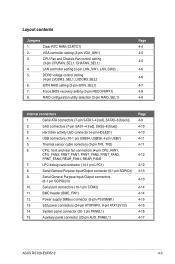
.../Output connector (6-1 pin SGPIO1) 9. Auxiliary panel connector (20-pin AUX_PANEL1) Page 4-9 4-10 4-10 4-11 4-11 4-12 4-12 4-13 4-13 4-14 4-14 4-15 4-15 4-16 4-17 ASUS RS720-E6/RS12 4-3 Force BIOS recovery setting (3-pin RECOVERY1) 8. LVDDR3_SEL2 6. iBTN RAID setting (3-pin IBTN_SEL1) 7. CPU, front and rear fan connectors (4-pin CPU_FAN1, CPU_FAN2, FRNT_FAN1, FRNT_FAN2, FRNT_FAN3, FRNT_FAN4...
.../Output connector (6-1 pin SGPIO1) 9. Auxiliary panel connector (20-pin AUX_PANEL1) Page 4-9 4-10 4-10 4-11 4-11 4-12 4-12 4-13 4-13 4-14 4-14 4-15 4-15 4-16 4-17 ASUS RS720-E6/RS12 4-3 Force BIOS recovery setting (3-pin RECOVERY1) 8. LVDDR3_SEL2 6. iBTN RAID setting (3-pin IBTN_SEL1) 7. CPU, front and rear fan connectors (4-pin CPU_FAN1, CPU_FAN2, FRNT_FAN1, FRNT_FAN2, FRNT_FAN3, FRNT_FAN4...


