

User Guide
Page 14
1.1 System package contents Check your system package for the following items. Model Name RS520-E8-RS12-EV2 RS520-E8-RS8 V2 Chassis ASUS 2U Rackmount Chassis ASUS F 2U Rackmount Chassis Motherboard ASUS Z10PR-D16 Server Board 1 x 770W Redundant Power Supply 1 x 770W Redundant Power Supply 12 x Hot-swap 3.5-inch HDD Trays ...x Tool-less Friction Rail Kit Additional 770W Redundant Power Supply 1 x Slim DVD Additional 770W Redundant Power Supply *ASUS System Web-based Management If any of the above items is damaged or missing, contact your retailer. 1-2 Chapter 1: Product Introduction
1.1 System package contents Check your system package for the following items. Model Name RS520-E8-RS12-EV2 RS520-E8-RS8 V2 Chassis ASUS 2U Rackmount Chassis ASUS F 2U Rackmount Chassis Motherboard ASUS Z10PR-D16 Server Board 1 x 770W Redundant Power Supply 1 x 770W Redundant Power Supply 12 x Hot-swap 3.5-inch HDD Trays ...x Tool-less Friction Rail Kit Additional 770W Redundant Power Supply 1 x Slim DVD Additional 770W Redundant Power Supply *ASUS System Web-based Management If any of the above items is damaged or missing, contact your retailer. 1-2 Chapter 1: Product Introduction
User Guide
Page 15
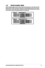
1.2 Serial number label Before requesting support from the ASUS Technical Support team, you must take note of the product, ASUS Technical Support team members can then offer a quicker and satisfying solution to your problems. RS520-E8-RS8 V2 xxS0xxxxxxxx RS520-E8-RS12-EV2 xxS0xxxxxxxx ASUS RS520-E8-RS8 V2, RS520-E8-RS12-EV2 1-3 With the correct serial number of the product's serial number containing 12 characters such as xxS0xxxxxxxx shown as the figure below.
1.2 Serial number label Before requesting support from the ASUS Technical Support team, you must take note of the product, ASUS Technical Support team members can then offer a quicker and satisfying solution to your problems. RS520-E8-RS8 V2 xxS0xxxxxxxx RS520-E8-RS12-EV2 xxS0xxxxxxxx ASUS RS520-E8-RS8 V2, RS520-E8-RS12-EV2 1-3 With the correct serial number of the product's serial number containing 12 characters such as xxS0xxxxxxxx shown as the figure below.

User Guide
Page 16
1.3 System specifications The ASUS RS520-E8-RS8 V2, RS520-E8-RS12-EV2 is a 1U barebone server system featuring the ASUS Z10PR-D16 Server Board. Model Name RS520-E8-RS12-EV2 RS520-E8-RS8 V2 Processor Support / System 2 x Socket R3 LGA 2011-3 Intel® Xeon® Processor E5-2600 v3 Family Bus QPI 6.4 / 8.0 / 9.6GT/s Core Logic Intel...per CPU) Capacity Maximum up to 1024 GB Memory Memory Type DDR4 2133 / 1866 / 1600 / 1333 RDIMM / LR-DIMM/ NVDIMM Refer to www.asus.com for the latest memory AVL update. 32GB, 16GB, 8GB and 4GB (RDIMM) Memory Size 64GB, 32GB (LRDIMM) Refer to www...
1.3 System specifications The ASUS RS520-E8-RS8 V2, RS520-E8-RS12-EV2 is a 1U barebone server system featuring the ASUS Z10PR-D16 Server Board. Model Name RS520-E8-RS12-EV2 RS520-E8-RS8 V2 Processor Support / System 2 x Socket R3 LGA 2011-3 Intel® Xeon® Processor E5-2600 v3 Family Bus QPI 6.4 / 8.0 / 9.6GT/s Core Logic Intel...per CPU) Capacity Maximum up to 1024 GB Memory Memory Type DDR4 2133 / 1866 / 1600 / 1333 RDIMM / LR-DIMM/ NVDIMM Refer to www.asus.com for the latest memory AVL update. 32GB, 16GB, 8GB and 4GB (RDIMM) Memory Size 64GB, 32GB (LRDIMM) Refer to www...

User Guide
Page 17
Model Name Networking LAN RS520-E8-RS12-EV2 RS520-E8-RS8 V2 2 x Intel® I210T + 1 x Management LAN 1 x Mezzanine 10G dual port LAN card Graphic VGA Aspeed AST2400 32MB 2 x RJ-45 GbE port 1 x RJ-45 management port ... Non operation temperature: -40°C - 70°C Non operation humidity: 20% - 90% (Non condensing) *Specifications are subject to change without notice. ASUS RS520-E8-RS8 V2, RS520-E8-RS12-EV2 1-5 Refer to www.asus.com for KVM-over-Internet Dimension (HH x WW x DD) Net Weight Kg (CPU, DRAM & HDD not included) Power Supply Power Rating Environment 615...
Model Name Networking LAN RS520-E8-RS12-EV2 RS520-E8-RS8 V2 2 x Intel® I210T + 1 x Management LAN 1 x Mezzanine 10G dual port LAN card Graphic VGA Aspeed AST2400 32MB 2 x RJ-45 GbE port 1 x RJ-45 management port ... Non operation temperature: -40°C - 70°C Non operation humidity: 20% - 90% (Non condensing) *Specifications are subject to change without notice. ASUS RS520-E8-RS8 V2, RS520-E8-RS12-EV2 1-5 Refer to www.asus.com for KVM-over-Internet Dimension (HH x WW x DD) Net Weight Kg (CPU, DRAM & HDD not included) Power Supply Power Rating Environment 615...

User Guide
Page 19
ASUS RS520-E8-RS8 V2, RS520-E8-RS12-EV2 1-7 RS520-E8-RS8 V2 PS/2 keyboard/mouse cpmbo port LAN port 2 VGA port Serial port (optional) Redundant power supply Mezzanine 10G dual-port LAN card (optional) Power connector DM management LAN port* 2 x USB 3.0 ports LAN port 1 RS520-E8-RS12-EV2 2.5-inch SSD Bay 2 2.5-inch SSD Bay 1 PS/2 keyboard/mouse cpmbo port LAN port 2 VGA port...
ASUS RS520-E8-RS8 V2, RS520-E8-RS12-EV2 1-7 RS520-E8-RS8 V2 PS/2 keyboard/mouse cpmbo port LAN port 2 VGA port Serial port (optional) Redundant power supply Mezzanine 10G dual-port LAN card (optional) Power connector DM management LAN port* 2 x USB 3.0 ports LAN port 1 RS520-E8-RS12-EV2 2.5-inch SSD Bay 2 2.5-inch SSD Bay 1 PS/2 keyboard/mouse cpmbo port LAN port 2 VGA port...

User Guide
Page 21
...supply 2. Connect a USB floppy disk drive to use a floppy disk. *WARNING HAZARDOUS MOVING PARTS KEEP FINGERS AND OTHER BODY PARTS AWAY ASUS RS520-E8-RS8 V2, RS520-E8-RS12-EV2 1-9 ASUS Z10PR-D16 Server Board 4. Hot-swap 3.5-inch HDD Bay 6 6 6 6 4 8 5 7 Turn off the system power and ... you need to any system component. Asset Tag 8. 1.6 Internal features The barebone server includes the basic components as shown. RS520-E8-RS8 V2 1. SATA/SAS back panel 3 5. Slim optical drive (optional) 1 6. The barebone server does not include a floppy disk drive. ...
...supply 2. Connect a USB floppy disk drive to use a floppy disk. *WARNING HAZARDOUS MOVING PARTS KEEP FINGERS AND OTHER BODY PARTS AWAY ASUS RS520-E8-RS8 V2, RS520-E8-RS12-EV2 1-9 ASUS Z10PR-D16 Server Board 4. Hot-swap 3.5-inch HDD Bay 6 6 6 6 4 8 5 7 Turn off the system power and ... you need to any system component. Asset Tag 8. 1.6 Internal features The barebone server includes the basic components as shown. RS520-E8-RS8 V2 1. SATA/SAS back panel 3 5. Slim optical drive (optional) 1 6. The barebone server does not include a floppy disk drive. ...

User Guide
Page 23
1.7 LED information 1.7.1 Front panel LEDs RS520-E8-RS8 V2 LAN4 LED (for Mezzanine card) LAN3 LED (for Mezzanine card) LAN2 LED LAN1 LED Message LED HDD Access LED RS520-E8-RS12-EV2 Power button with LED Message LED Location button with LED LAN1 LED LAN2 LED 4 3 2 1 Location button with LED Power... Read/write data into the HDD Message LED OFF System is pressed Normal status (Press the location switch again to turn off) ASUS RS520-E8-RS8 V2, RS520-E8-RS12-EV2 1-11 no incoming event ON With the onboard ASMB8-iKVM: a hardware monitor event is indicated OFF No LAN connection Blinking ...
1.7 LED information 1.7.1 Front panel LEDs RS520-E8-RS8 V2 LAN4 LED (for Mezzanine card) LAN3 LED (for Mezzanine card) LAN2 LED LAN1 LED Message LED HDD Access LED RS520-E8-RS12-EV2 Power button with LED Message LED Location button with LED LAN1 LED LAN2 LED 4 3 2 1 Location button with LED Power... Read/write data into the HDD Message LED OFF System is pressed Normal status (Press the location switch again to turn off) ASUS RS520-E8-RS8 V2, RS520-E8-RS12-EV2 1-11 no incoming event ON With the onboard ASMB8-iKVM: a hardware monitor event is indicated OFF No LAN connection Blinking ...

User Guide
Page 27
... Intel® Xeon E5-2600 v3 processor family. There is shipment/transitrelated. • Keep the cap after installing the motherboard. ASUS RS520-E8-RS8 V2, RS520-E8-RS12-EV2 2-3 Contact your retailer immediately if the PnP cap is on the illustration below to the socket contacts resulting from incorrect CPU ...Central Processing Unit (CPU) The motherboard comes with two surface mount LGA 2011-3 sockets designed for the position of the air duct). ASUS shoulders the repair cost only if the damage is a screw at the left corner on the socket and the socket contacts are unplugged...
... Intel® Xeon E5-2600 v3 processor family. There is shipment/transitrelated. • Keep the cap after installing the motherboard. ASUS RS520-E8-RS8 V2, RS520-E8-RS12-EV2 2-3 Contact your retailer immediately if the PnP cap is on the illustration below to the socket contacts resulting from incorrect CPU ...Central Processing Unit (CPU) The motherboard comes with two surface mount LGA 2011-3 sockets designed for the position of the air duct). ASUS shoulders the repair cost only if the damage is a screw at the left corner on the socket and the socket contacts are unplugged...

User Guide
Page 29
Do not insert the load lever into the retention tab. 6. Gently push the right load lever down to the right (E) until it is released from the retention tab (F), then gently pull it until it to slightly lift the load plate (G). 4. edge of the Load plate Load plate Load lever ASUS RS520-E8-RS8 V2, RS520-E8-RS12-EV2 2-5 Hold the edge then gently lift the load plate (H). Press the left load lever (D), move it is fully extended. 5.
Do not insert the load lever into the retention tab. 6. Gently push the right load lever down to the right (E) until it is released from the retention tab (F), then gently pull it until it to slightly lift the load plate (G). 4. edge of the Load plate Load plate Load lever ASUS RS520-E8-RS8 V2, RS520-E8-RS12-EV2 2-5 Hold the edge then gently lift the load plate (H). Press the left load lever (D), move it is fully extended. 5.

User Guide
Page 31
edge of the load plate is fixed and tucked securely under the retention tab (M). Push the left load lever down (K) ensuring that the edge of the load plate is fixed and tucked securely under the lever (L), then insert the right load lever under the lever (J), then the PnP cap will eject automatically. PnP cap 12. 11. Push the right load lever down (I) ensuring that the edge of load plate Load lever Retention tab ASUS RS520-E8-RS8 V2, RS520-E8-RS12-EV2 2-7
edge of the load plate is fixed and tucked securely under the retention tab (M). Push the left load lever down (K) ensuring that the edge of the load plate is fixed and tucked securely under the lever (L), then insert the right load lever under the lever (J), then the PnP cap will eject automatically. PnP cap 12. 11. Push the right load lever down (I) ensuring that the edge of load plate Load lever Retention tab ASUS RS520-E8-RS8 V2, RS520-E8-RS12-EV2 2-7

User Guide
Page 33
... 32 GB RDIMMs or 32 GB, 64 GB LR-DIMMs and NVDIMM into the DIMM sockets using the memory configurations in slots A2 or B2. ASUS RS520-E8-RS8 V2, RS520-E8-RS12-EV2 2-9 2.3 System memory 2.3.1 Overview The motherboard comes with the same CAS latency.
... 32 GB RDIMMs or 32 GB, 64 GB LR-DIMMs and NVDIMM into the DIMM sockets using the memory configurations in slots A2 or B2. ASUS RS520-E8-RS8 V2, RS520-E8-RS12-EV2 2-9 2.3 System memory 2.3.1 Overview The motherboard comes with the same CAS latency.

User Guide
Page 35
... in only one direction. DIMM notch DIMM slot key Unlocked retaining clip A DIMM is sitting firmly on the socket. Remove the DIMM from the socket. ASUS RS520-E8-RS8 V2, RS520-E8-RS12-EV2 2-11 Failure to do so may cause severe damage to prevent DIMM notch damage. 2.3.4 Removing a DIMM 1. Ensure that the DIMM is keyed with...
... in only one direction. DIMM notch DIMM slot key Unlocked retaining clip A DIMM is sitting firmly on the socket. Remove the DIMM from the socket. ASUS RS520-E8-RS8 V2, RS520-E8-RS12-EV2 2-11 Failure to do so may cause severe damage to prevent DIMM notch damage. 2.3.4 Removing a DIMM 1. Ensure that the DIMM is keyed with...

User Guide
Page 37
ASUS RS520-E8-RS8 V2, RS520-E8-RS12-EV2 2-13 Firmly hold the tray lever then pull the drive tray out of the bay ( A ) and push the tray lever until it clicks and ... correctly placed when its front edge aligns with the bay edge. Repeat steps 1 to 5 to install other 3.5-inch SATA II/SAS HDDs. 2.4.2 Installing a 2.5-inch SSD (RS520-E8-RS12-EV2 only) To install a 2.5-inch SSD: 1. 5.
ASUS RS520-E8-RS8 V2, RS520-E8-RS12-EV2 2-13 Firmly hold the tray lever then pull the drive tray out of the bay ( A ) and push the tray lever until it clicks and ... correctly placed when its front edge aligns with the bay edge. Repeat steps 1 to 5 to install other 3.5-inch SATA II/SAS HDDs. 2.4.2 Installing a 2.5-inch SSD (RS520-E8-RS12-EV2 only) To install a 2.5-inch SSD: 1. 5.

User Guide
Page 39
Remove the screws that secure the metal cover to install Low-Profile PCI Express expansion cards. Remove the metal cover then set it aside. 2. 2.5 Expansion slot The barebone server comes with two riser card brackets allowing you to the chassis. 3. Remove two screws on the bracket and put it aside for RS520-E8-RS8 V2. 2.5.1 Installing an expansion card to the PCI-E slot To install an expansion card: 1. The steps below are only for future use. ASUS RS520-E8-RS8 V2, RS520-E8-RS12-EV2 2-15
Remove the screws that secure the metal cover to install Low-Profile PCI Express expansion cards. Remove the metal cover then set it aside. 2. 2.5 Expansion slot The barebone server comes with two riser card brackets allowing you to the chassis. 3. Remove two screws on the bracket and put it aside for RS520-E8-RS8 V2. 2.5.1 Installing an expansion card to the PCI-E slot To install an expansion card: 1. The steps below are only for future use. ASUS RS520-E8-RS8 V2, RS520-E8-RS12-EV2 2-15

User Guide
Page 41
Remove two screws on the provided PCI-E slot onboard. To install an ASUS PIKE II card: 1. Remove the default cable from the motherboard and the backplane. 2. ASUS RS520-E8-RS8 V2, RS520-E8-RS12-EV2 2-17 2.5.2 Installing an ASUS PIKE II card (RS520-E8-RS8 only) You can install an ASUS PIKE II card on the bracket and put it aside.
Remove two screws on the provided PCI-E slot onboard. To install an ASUS PIKE II card: 1. Remove the default cable from the motherboard and the backplane. 2. ASUS RS520-E8-RS8 V2, RS520-E8-RS12-EV2 2-17 2.5.2 Installing an ASUS PIKE II card (RS520-E8-RS8 only) You can install an ASUS PIKE II card on the bracket and put it aside.
User Guide
Page 43
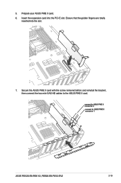
Ensure that the golden fingers are totally inserted into the PCI-E slot. connect to ASUS PIKE II connector 2 connect to the ASUS PIKE II card. 5. Prepare your ASUS PIKE II card. 6. Insert the expansion card into the slot. 7. Secure the ASUS PIKE II card with the screw removed before and reinstall the bracket, then connect the two mini-SAS HD cables to ASUS PIKE II connector 1 ASUS RS520-E8-RS8 V2, RS520-E8-RS12-EV2 2-19
Ensure that the golden fingers are totally inserted into the PCI-E slot. connect to ASUS PIKE II connector 2 connect to the ASUS PIKE II card. 5. Prepare your ASUS PIKE II card. 6. Insert the expansion card into the slot. 7. Secure the ASUS PIKE II card with the screw removed before and reinstall the bracket, then connect the two mini-SAS HD cables to ASUS PIKE II connector 1 ASUS RS520-E8-RS8 V2, RS520-E8-RS12-EV2 2-19
User Guide
Page 45
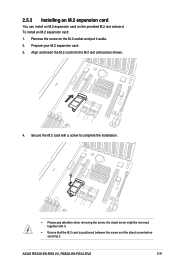
... before securing it aside. 2. 2.5.3 Installing an M.2 expansion card You can install an M.2 expansion card on the M.2 socket and put it . To install an M.2 expansion card: 1. ASUS RS520-E8-RS8 V2, RS520-E8-RS12-EV2 2-21
... before securing it aside. 2. 2.5.3 Installing an M.2 expansion card You can install an M.2 expansion card on the M.2 socket and put it . To install an M.2 expansion card: 1. ASUS RS520-E8-RS8 V2, RS520-E8-RS12-EV2 2-21

User Guide
Page 47
OCP_LED1 The two ends of the signal cable are different in size and color for easy recognition. ASUS RS520-E8-RS8 V2, RS520-E8-RS12-EV2 2-23 Please refer to the OCP_LED1 header on the motherboard. 4. Secure the Mezzanine card with the four (4) bundled screws. 5. Connect the signal end (black) to your exact cable.
OCP_LED1 The two ends of the signal cable are different in size and color for easy recognition. ASUS RS520-E8-RS8 V2, RS520-E8-RS12-EV2 2-23 Please refer to the OCP_LED1 header on the motherboard. 4. Secure the Mezzanine card with the four (4) bundled screws. 5. Connect the signal end (black) to your exact cable.

User Guide
Page 49
USB connector (from motherboard to front I/O board) 5. from motherboard to SATA/SAS backplane) 6. System auxiliary panel connector (from motherboard to front I /O board) ASUS RS520-E8-RS8 V2, RS520-E8-RS12-EV2 2-25 SATA ports connectors (system default; System panel connector (from motherboard to front I /O board) 7. 2.6 Cable connections • The bundled system cables are pre-connected ...
USB connector (from motherboard to front I/O board) 5. from motherboard to SATA/SAS backplane) 6. System auxiliary panel connector (from motherboard to front I /O board) ASUS RS520-E8-RS8 V2, RS520-E8-RS12-EV2 2-25 SATA ports connectors (system default; System panel connector (from motherboard to front I /O board) 7. 2.6 Cable connections • The bundled system cables are pre-connected ...

User Guide
Page 51
With two mini-SAS HD cables connected, a total number of 12 SAS/SATA HDDs can be supported (SAS/SATA expander on the backplane. RS520-E8-RS12-EV2 connect to the 8-pin power connector connect to the SMB(6-1 pin FPSMB) connector on the auxiliary panel ASUS RS520-E8-RS8 V2, RS520-E8-RS12-EV2 2-27 MSAS_HD1 MSAS_HD2 ® BP12EX12G-35-R2DF MSAS_HD3 Reserved for future expansions ® BP12EX12G-35-R2DF BPSMB1: connect to mini-SAS HD connectors 1 and 2 on the rear panel).
With two mini-SAS HD cables connected, a total number of 12 SAS/SATA HDDs can be supported (SAS/SATA expander on the backplane. RS520-E8-RS12-EV2 connect to the 8-pin power connector connect to the SMB(6-1 pin FPSMB) connector on the auxiliary panel ASUS RS520-E8-RS8 V2, RS520-E8-RS12-EV2 2-27 MSAS_HD1 MSAS_HD2 ® BP12EX12G-35-R2DF MSAS_HD3 Reserved for future expansions ® BP12EX12G-35-R2DF BPSMB1: connect to mini-SAS HD connectors 1 and 2 on the rear panel).


