
User Guide
Page 6
...Option ROM utility 6-29 6.3.5 Rebuilding the RAID 6-29 6.3.6 Setting the Boot array in the BIOS Setup Utility 6-31 6.4 Intel® Rapid Storage Technology enterprise (Windows 6-32 6.4.1 Creating a RAID set 6-33 6.4.2 Changing a Volume Type 6-35 6.4.3 Deleting a volume 6-36 6.4.4 Preferences 6-37 Chapter 7: Driver Installation 7.1 RAID driver installation 7-2 7.1.1 Creating a RAID driver disk 7-2 7.1.2 Installing the RAID controller driver 7-4 7.2 Management applications and utilities installation 7-14 7.3 Running the Support DVD 7-14 7.4 Intel® chipset device software...
...Option ROM utility 6-29 6.3.5 Rebuilding the RAID 6-29 6.3.6 Setting the Boot array in the BIOS Setup Utility 6-31 6.4 Intel® Rapid Storage Technology enterprise (Windows 6-32 6.4.1 Creating a RAID set 6-33 6.4.2 Changing a Volume Type 6-35 6.4.3 Deleting a volume 6-36 6.4.4 Preferences 6-37 Chapter 7: Driver Installation 7.1 RAID driver installation 7-2 7.1.1 Creating a RAID driver disk 7-2 7.1.2 Installing the RAID controller driver 7-4 7.2 Management applications and utilities installation 7-14 7.3 Running the Support DVD 7-14 7.4 Intel® chipset device software...
User Guide
Page 10
..., jumper settings, and connector locations. 5. Chapter 1: Product Introduction This chapter describes the general features of configuring a server. About this guide Audience This user guide is intended for different system components. Chapter 2: Hardware Information This chapter lists the hardware setup procedures that comes with at least basic knowledge of the server, including sections on front panel and rear panel specifications. 2. Detailed descriptions of the BIOS parameters are also provided. 7 Chapter 7: Driver Installation...
..., jumper settings, and connector locations. 5. Chapter 1: Product Introduction This chapter describes the general features of configuring a server. About this guide Audience This user guide is intended for different system components. Chapter 2: Hardware Information This chapter lists the hardware setup procedures that comes with at least basic knowledge of the server, including sections on front panel and rear panel specifications. 2. Detailed descriptions of the BIOS parameters are also provided. 7 Chapter 7: Driver Installation...
User Guide
Page 11
NOTE: Tips and additional information to complete a task. Typography Bold text Italics + Conventions To ensure that you MUST follow to complete a task. CAUTION: Information to prevent damage to the components when trying to help you perform certain tasks properly, take note of the following symbols used throughout this manual. IMPORTANT: Instructions that you complete a task. DANGER/WARNING: Information to prevent injury to yourself when trying to complete a task.
NOTE: Tips and additional information to complete a task. Typography Bold text Italics + Conventions To ensure that you MUST follow to complete a task. CAUTION: Information to prevent damage to the components when trying to help you perform certain tasks properly, take note of the following symbols used throughout this manual. IMPORTANT: Instructions that you complete a task. DANGER/WARNING: Information to prevent injury to yourself when trying to complete a task.

User Guide
Page 16
supports software RAID 0, 1, 10 and 5) LSI® MegaRAID driver supports RAID 0, 1 and 10) (for Windows only; Total Slots PCI/PCI-E 3+1 Expansion Slots (follow SSI Location #) Slot Type Low-profile 1 x PCI-E Gen3 x16 (x8 link) 2 x PCI-E Gen3 x8 (x8 link) 1 x PCI-E Gen3 x8 (x8 Gen3 link) (for OCP Mezzanine*) * Supports MCB-10G series (10 Gigabit/s series Gigabit Ethernet LAN card) (Optional) Intel® C612 9 x SATA 6 Gbps ports (8 x 2 mini-SAS connectors) Storage 1 x discrete M.2 socket SATA Controller Intel® RSTe (for Linux and Windows) ASUS PIKE II 3008...
supports software RAID 0, 1, 10 and 5) LSI® MegaRAID driver supports RAID 0, 1 and 10) (for Windows only; Total Slots PCI/PCI-E 3+1 Expansion Slots (follow SSI Location #) Slot Type Low-profile 1 x PCI-E Gen3 x16 (x8 link) 2 x PCI-E Gen3 x8 (x8 link) 1 x PCI-E Gen3 x8 (x8 Gen3 link) (for OCP Mezzanine*) * Supports MCB-10G series (10 Gigabit/s series Gigabit Ethernet LAN card) (Optional) Intel® C612 9 x SATA 6 Gbps ports (8 x 2 mini-SAS connectors) Storage 1 x discrete M.2 socket SATA Controller Intel® RSTe (for Linux and Windows) ASUS PIKE II 3008...

User Guide
Page 21
Power supply fan 2 3. Asset Tag 8. Connect a USB floppy disk drive to use a floppy disk. *WARNING HAZARDOUS MOVING PARTS KEEP FINGERS AND OTHER BODY PARTS AWAY ASUS RS520-E8-RS8 V2, RS520-E8-RS12-EV2 1-9 RS520-E8-RS8 V2 1. SATA/SAS back panel 3 5. The barebone server does not include a floppy disk drive. Slim optical drive (optional) 1 6. Hot-swap 3.5-inch HDD Bay 6 6 6 6 4 8 5 7 Turn off the system power and detach the power supply before removing or replacing any of the USB ports on the front or rear panel if you need to any system...
Power supply fan 2 3. Asset Tag 8. Connect a USB floppy disk drive to use a floppy disk. *WARNING HAZARDOUS MOVING PARTS KEEP FINGERS AND OTHER BODY PARTS AWAY ASUS RS520-E8-RS8 V2, RS520-E8-RS12-EV2 1-9 RS520-E8-RS8 V2 1. SATA/SAS back panel 3 5. The barebone server does not include a floppy disk drive. Slim optical drive (optional) 1 6. Hot-swap 3.5-inch HDD Bay 6 6 6 6 4 8 5 7 Turn off the system power and detach the power supply before removing or replacing any of the USB ports on the front or rear panel if you need to any system...

User Guide
Page 33
ASUS RS520-E8-RS8 V2, RS520-E8-RS12-EV2 2-9 The figure illustrates the location of the DDR4 DIMM sockets: 2.3.2 Memory Configurations You may install 4 GB, 8 GB, 16 GB, and 32 GB RDIMMs or 32 GB, 64 GB LR-DIMMs and NVDIMM into the DIMM sockets using the memory configurations in slots A2 or B2. For optimum compatibility, it is recommended that you obtain memory modules from the same vendor. • Start installing the...
ASUS RS520-E8-RS8 V2, RS520-E8-RS12-EV2 2-9 The figure illustrates the location of the DDR4 DIMM sockets: 2.3.2 Memory Configurations You may install 4 GB, 8 GB, 16 GB, and 32 GB RDIMMs or 32 GB, 64 GB LR-DIMMs and NVDIMM into the DIMM sockets using the memory configurations in slots A2 or B2. For optimum compatibility, it is recommended that you obtain memory modules from the same vendor. • Start installing the...
User Guide
Page 48
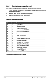
... software settings. 1. Refer to the card. Install the software drivers for ISA or PCI devices. 2-24 Chapter 2: Hardware Information See Chapter 5 for information on the system and change the necessary BIOS settings, if any. Standard Interrupt assignments IRQ Priority Standard function 0 1 System Timer 1 2 Keyboard Controller 2 - Programmable Interrupt 3* 11 Communications Port (COM2) 4* 12 Communications Port (COM1) 5* 13 -- 6 14 Floppy Disk Controller 7* 15 -- 8 3 System CMOS/Real Time Clock 9* 4 ACPI Mode when used...
... software settings. 1. Refer to the card. Install the software drivers for ISA or PCI devices. 2-24 Chapter 2: Hardware Information See Chapter 5 for information on the system and change the necessary BIOS settings, if any. Standard Interrupt assignments IRQ Priority Standard function 0 1 System Timer 1 2 Keyboard Controller 2 - Programmable Interrupt 3* 11 Communications Port (COM2) 4* 12 Communications Port (COM1) 5* 13 -- 6 14 Floppy Disk Controller 7* 15 -- 8 3 System CMOS/Real Time Clock 9* 4 ACPI Mode when used...

User Guide
Page 49
...System panel connector (from motherboard to front I/O board) ASUS RS520-E8-RS8 V2, RS520-E8-RS12-EV2 2-25 You do not need to disconnect these cables unless you need to remove pre‑installed components to install additional devices. • Refer to Chapter 4 for detailed information on the connectors. 3 76 1 2 4 3 3 3 3 3 5 3 3 45 Standard cables connected to the motherboard 1. 24-pin ATX power connector (from power supply to motherboard) 2. 8-pin 12V power connector (from system fan to motherboard) 3. System fan connector (from power supply to motherboard) 4. USB connector...
...System panel connector (from motherboard to front I/O board) ASUS RS520-E8-RS8 V2, RS520-E8-RS12-EV2 2-25 You do not need to disconnect these cables unless you need to remove pre‑installed components to install additional devices. • Refer to Chapter 4 for detailed information on the connectors. 3 76 1 2 4 3 3 3 3 3 5 3 3 45 Standard cables connected to the motherboard 1. 24-pin ATX power connector (from power supply to motherboard) 2. 8-pin 12V power connector (from system fan to motherboard) 3. System fan connector (from power supply to motherboard) 4. USB connector...

User Guide
Page 117
...sSATA Controller [Enabled] Allows you to enable or disable the Support Aggressive Link Power (SALP) Management. Configuration options: [IDE] [AHCI] [RAID] SATA Mode options SATA LED locate [Enabled] If enabled, LED/SGPIO hardware is connected to Solid State Drive or Hard Disk Drive. Configuration options: [Disabled] [Enabled] Configure sSATA as [AHCI] Allows you to configure the PCI Express Root port settings. Configuration options: [Disabled] [Enabled] ASUS RS520-E8-RS8 V2, RS520-E8-RS12-EV2 5-35 PCH DMI ASPM [Enabled] Allows you to configure the PCH DMI ASPM. PCIE ASMP [Disable...
...sSATA Controller [Enabled] Allows you to enable or disable the Support Aggressive Link Power (SALP) Management. Configuration options: [IDE] [AHCI] [RAID] SATA Mode options SATA LED locate [Enabled] If enabled, LED/SGPIO hardware is connected to Solid State Drive or Hard Disk Drive. Configuration options: [Disabled] [Enabled] Configure sSATA as [AHCI] Allows you to configure the PCI Express Root port settings. Configuration options: [Disabled] [Enabled] ASUS RS520-E8-RS8 V2, RS520-E8-RS12-EV2 5-35 PCH DMI ASPM [Enabled] Allows you to configure the PCH DMI ASPM. PCIE ASMP [Disable...

User Guide
Page 119
Configuration options: [Disabled] [Enabled] The following items appears only when the USB Ports Per-Port Disable Control is set to enable or disable the PCH Thermal Device (D31:F6). Configuration options: [Auto] [Disabled] [Enabled] ASUS RS520-E8-RS8 V2, RS520-E8-RS12-EV2 5-37 USB Port #1/ #2/ #3/ #4 [Enabled] Configuration options: [Disabled] [Enabled] USB 3.0 Port #1/ #2 [Enabled] Configuration options: [Disabled] [Enabled] Platform Thermal Configuration PCH Thermal Device [Auto] Allows you to control each of the USB ports 1 to 8 disabling. USB Ports Per-Port Disable Control [Disabled]...
Configuration options: [Disabled] [Enabled] The following items appears only when the USB Ports Per-Port Disable Control is set to enable or disable the PCH Thermal Device (D31:F6). Configuration options: [Auto] [Disabled] [Enabled] ASUS RS520-E8-RS8 V2, RS520-E8-RS12-EV2 5-37 USB Port #1/ #2/ #3/ #4 [Enabled] Configuration options: [Disabled] [Enabled] USB 3.0 Port #1/ #2 [Enabled] Configuration options: [Disabled] [Enabled] Platform Thermal Configuration PCH Thermal Device [Auto] Allows you to control each of the USB ports 1 to 8 disabling. USB Ports Per-Port Disable Control [Disabled]...

User Guide
Page 121
ASUS RS520-E8-RS8 V2, RS520-E8-RS12-EV2 5-39 OS Watchdog Timer [Disabled] This item allows you to [Enabled]. Configuration options: [Disabled] [Enabled] The following items is configurable only when the OS Watchdog Timer is set to start a BIOS timer which can only be shut off by Intel Management Software after the OS loads. Configuration options: [Disabled] [Enabled] 5.6 Server Mgmt menu The Server Management menu displays the server management status and allows you to enable or disable the WHEA support. 5.5.10 Runtime Error Logging Support Runtime...
ASUS RS520-E8-RS8 V2, RS520-E8-RS12-EV2 5-39 OS Watchdog Timer [Disabled] This item allows you to [Enabled]. Configuration options: [Disabled] [Enabled] The following items is configurable only when the OS Watchdog Timer is set to start a BIOS timer which can only be shut off by Intel Management Software after the OS loads. Configuration options: [Disabled] [Enabled] 5.6 Server Mgmt menu The Server Management menu displays the server management status and allows you to enable or disable the WHEA support. 5.5.10 Runtime Error Logging Support Runtime...

User Guide
Page 138
... RAID. 6-2 Chapter 6: RAID Configuration Move the jumper to the entire system. 6.1 Setting up RAID The motherboard supports the following SATA RAID solutions: • Intel® Rapid Storage Technology enterprise Option ROM Utility with RAID 0, RAID 1, RAID 10, and RAID 5 support (for Windows OS only). 6.1.1 RAID definitions RAID 0 (Data striping) optimizes two identical hard disk drives to read and write data in a created RAID set, copy first the RAID driver from the support DVD to a floppy disk before you install an operating system to the selected hard disk drive...
... RAID. 6-2 Chapter 6: RAID Configuration Move the jumper to the entire system. 6.1 Setting up RAID The motherboard supports the following SATA RAID solutions: • Intel® Rapid Storage Technology enterprise Option ROM Utility with RAID 0, RAID 1, RAID 10, and RAID 5 support (for Windows OS only). 6.1.1 RAID definitions RAID 0 (Data striping) optimizes two identical hard disk drives to read and write data in a created RAID set, copy first the RAID driver from the support DVD to a floppy disk before you install an operating system to the selected hard disk drive...
User Guide
Page 139
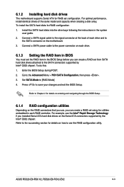
... the BIOS Setup during POST. 2. Refer to Chapter 4 for RAID configuration: 1. To do this: 1. Set SATA Mode to save your changes and exit the BIOS Setup. ASUS RS520-E8-RS8 V2, RS520-E8-RS12-EV2 6-3 Press to [RAID Mode] 4. For optimal performance, install identical drives of each RAID controller. For example, use the Intel® Rapid Storage Technology if you installed Serial ATA hard disk drives on the Serial ATA connectors supported by Intel® C602 chipset. Connect a SATA power cable to the power connector on each drive. 6.1.3 Setting the RAID item in BIOS...
... the BIOS Setup during POST. 2. Refer to Chapter 4 for RAID configuration: 1. To do this: 1. Set SATA Mode to save your changes and exit the BIOS Setup. ASUS RS520-E8-RS8 V2, RS520-E8-RS12-EV2 6-3 Press to [RAID Mode] 4. For optimal performance, install identical drives of each RAID controller. For example, use the Intel® Rapid Storage Technology if you installed Serial ATA hard disk drives on the Serial ATA connectors supported by Intel® C602 chipset. Connect a SATA power cable to the power connector on each drive. 6.1.3 Setting the RAID item in BIOS...
User Guide
Page 140
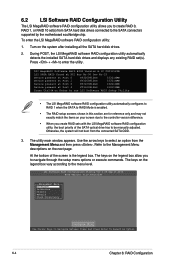
Use the arrow keys to the Management Menu descriptions on the next page. During POST, the LSI MegaRAID software RAID configuration utility automatically detects the installed SATA hard disk drives and displays any existing RAID set (s) from SATA hard disk drives connected to navigate through the setup menu options or execute commands. The utility main window appears. Refer to select an option from the connected SATA ODD. 3. At the bottom of the SATA optical drive has to be manually adjusted. To enter the LSI...
Use the arrow keys to the Management Menu descriptions on the next page. During POST, the LSI MegaRAID software RAID configuration utility automatically detects the installed SATA hard disk drives and displays any existing RAID set (s) from SATA hard disk drives connected to navigate through the setup menu options or execute commands. The utility main window appears. Refer to select an option from the connected SATA ODD. 3. At the bottom of the SATA optical drive has to be manually adjusted. To enter the LSI...

User Guide
Page 142
... four identical hard disk drives when creating a RAID 10 set , and then press . LSI Software RAID Configuration Utility Ver C.05 Sep 17,2010 BIOS Version A.10.09231523R Easy Configuration - Select all the drives required for the RAID set, and then press to the SATA ports. The ARRAY SELECTION MENU displays the available drives connected to configure array setting. 4. ARRAY SELECTION MENU Configure SelectPOCRoTnf#igurable Array(s) Initialize Objects Rebuild A-0 0 ONLIN A00-00 SPAN-1 1 ONLIN A00-01 Check Consistency 2 READY 3 READY Cursor Keys, SPACE...
... four identical hard disk drives when creating a RAID 10 set , and then press . LSI Software RAID Configuration Utility Ver C.05 Sep 17,2010 BIOS Version A.10.09231523R Easy Configuration - Select all the drives required for the RAID set, and then press to the SATA ports. The ARRAY SELECTION MENU displays the available drives connected to configure array setting. 4. ARRAY SELECTION MENU Configure SelectPOCRoTnf#igurable Array(s) Initialize Objects Rebuild A-0 0 ONLIN A00-00 SPAN-1 1 ONLIN A00-01 Check Consistency 2 READY 3 READY Cursor Keys, SPACE...

User Guide
Page 147
...,F2-Drive Info,F3-Virtual Drives,F4-HSP The information of the selected hard disk drive displays at the bottom of section 6.2.1 Creating a RAID set . ASUS RS520-E8-RS8 V2, RS520-E8-RS12-EV2 6-11 LSI Software RAID Configuration Utility Ver C.05 Sep 17,2010 BIOS Version A.10.09231523R Configuration Menu Easy Configuration Management MenuNew Configuration Configure View/Add Configuration Initialize Clear Configuration Objects Select Boot Drive Rebuild Check Consistency View/Add to add a new RAID set : Using Easy Configuration to The Existing Configuration Use Cursor Keys To...
...,F2-Drive Info,F3-Virtual Drives,F4-HSP The information of the selected hard disk drive displays at the bottom of section 6.2.1 Creating a RAID set . ASUS RS520-E8-RS8 V2, RS520-E8-RS12-EV2 6-11 LSI Software RAID Configuration Utility Ver C.05 Sep 17,2010 BIOS Version A.10.09231523R Configuration Menu Easy Configuration Management MenuNew Configuration Configure View/Add Configuration Initialize Clear Configuration Objects Select Boot Drive Rebuild Check Consistency View/Add to add a new RAID set : Using Easy Configuration to The Existing Configuration Use Cursor Keys To...

User Guide
Page 150
... . LSI Software RAID Configuration Utility Ver C.05 Sep 17,2010 BIOS Version A.10.09231523R Objects Management Configure MAednaupter Virtual Drive Initialize Physical Drive Objects Rebuild Check Consistency Virtual Drive(1) Virtual Drive 0 Select VD Press ENTER To Select A VD, To Delete A VD 6-14 Chapter 6: RAID Configuration LSI Software RAID Configuration Utility Ver C.05 Sep 17,2010 BIOS Version A.10.09231523R Objects Management MAednaupter Configure Virtual Drive Initialize Physical Drive Objects Rebuild Check Consistency Change VD Parameters Use Cursor Keys To...
... . LSI Software RAID Configuration Utility Ver C.05 Sep 17,2010 BIOS Version A.10.09231523R Objects Management Configure MAednaupter Virtual Drive Initialize Physical Drive Objects Rebuild Check Consistency Virtual Drive(1) Virtual Drive 0 Select VD Press ENTER To Select A VD, To Delete A VD 6-14 Chapter 6: RAID Configuration LSI Software RAID Configuration Utility Ver C.05 Sep 17,2010 BIOS Version A.10.09231523R Objects Management MAednaupter Configure Virtual Drive Initialize Physical Drive Objects Rebuild Check Consistency Change VD Parameters Use Cursor Keys To...

User Guide
Page 159
... Management Menu, select Objects > Virtual Drive, select an existing adapter and press . Select Disk WC, and then press to turn on the option. ASUS RS520-E8-RS8 V2, RS520-E8-RS12-EV2 6-23 The WriteCache function is recommended for RAID 1 and RAID 10 sets. Select Disk WC, and then press to turn on the option. When you enable WriteCache, you may manually enable the RAID controller's WriteCache option after creating a RAID set to display the adapter properties. 4. To enable...
... Management Menu, select Objects > Virtual Drive, select an existing adapter and press . Select Disk WC, and then press to turn on the option. ASUS RS520-E8-RS8 V2, RS520-E8-RS12-EV2 6-23 The WriteCache function is recommended for RAID 1 and RAID 10 sets. Select Disk WC, and then press to turn on the option. When you enable WriteCache, you may manually enable the RAID controller's WriteCache option after creating a RAID set to display the adapter properties. 4. To enable...

User Guide
Page 160
... installed the Serial ATA hard disk drives, have set the correct jumper settings of the screen allow you proceed, ensure that are for more information. You can refer to sections Installing hard disk drives, Setting Jumpers, and Setting the RAID mode in BIOS for reference only and may not exactly match the items on the system. 2. During POST, press + to Non-RAID 4. Reset Disks to display the utility main menu. Turn on your screen. 6-24 Chapter 6: RAID Configuration...
... installed the Serial ATA hard disk drives, have set the correct jumper settings of the screen allow you proceed, ensure that are for more information. You can refer to sections Installing hard disk drives, Setting Jumpers, and Setting the RAID mode in BIOS for reference only and may not exactly match the items on the system. 2. During POST, press + to Non-RAID 4. Reset Disks to display the utility main menu. Turn on your screen. 6-24 Chapter 6: RAID Configuration...
User Guide
Page 176
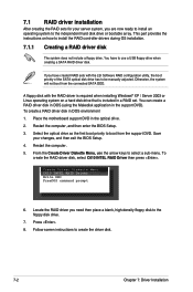
... system will not boot from the support DVD. A floppy disk with the LSI Software RAID configuration utility, the boot priority of the SATA optical disk drive has to the independent hard disk drive or bootable array. Restart the computer. 5. You have created RAID sets with the RAID driver is required when installing Windows® XP / Server 2003 or Linux operating system on how to create the driver disk. 7-2 Chapter 7: Driver Installation To create a RAID driver disk in a RAID set. Select the optical drive as the first...
... system will not boot from the support DVD. A floppy disk with the LSI Software RAID configuration utility, the boot priority of the SATA optical disk drive has to the independent hard disk drive or bootable array. Restart the computer. 5. You have created RAID sets with the RAID driver is required when installing Windows® XP / Server 2003 or Linux operating system on how to create the driver disk. 7-2 Chapter 7: Driver Installation To create a RAID driver disk in a RAID set. Select the optical drive as the first...


