
User Guide
Page 15
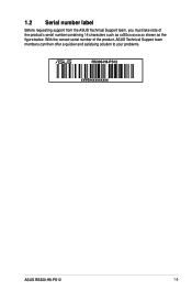
With the correct serial number of the product's serial number containing 14 characters such as xxS0xxxxxxxxxx shown as the figure below. 1.2 Serial number label Before requesting support from the ASUS Technical Support team, you must take note of the product, ASUS Technical Support team members can then offer a quicker and satisfying solution to your problems. RS300-H8-PS12 xxS0xxxxxxxxxx ASUS RS300-H8-PS12 1-3
With the correct serial number of the product's serial number containing 14 characters such as xxS0xxxxxxxxxx shown as the figure below. 1.2 Serial number label Before requesting support from the ASUS Technical Support team, you must take note of the product, ASUS Technical Support team members can then offer a quicker and satisfying solution to your problems. RS300-H8-PS12 xxS0xxxxxxxxxx ASUS RS300-H8-PS12 1-3
User Guide
Page 16
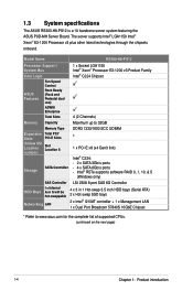
...other latest technologies through the chipsets onboard. 1.3 System specifications The ASUS RS300-H8-PS12 is a 1U barebone server system featuring the ASUS P9D-MH Server Board. Model Name RS300-H8-PS12 Processor Support / System Bus Core Logic Fan Speed Control ASUS Features Rack Ready (Rack and Pedestal dual use) ASWM Enterprise Total... Hot-swap SSD bays 2 x Intel® I210AT controller + 1 x Management LAN 1 x Dual Port Broadcom 57840S 10GbE Chipset * Refer to www.asus.com for the complete list of supported CPUs. (continued on the next page) 1-4 Chapter 1: Product introduction
...other latest technologies through the chipsets onboard. 1.3 System specifications The ASUS RS300-H8-PS12 is a 1U barebone server system featuring the ASUS P9D-MH Server Board. Model Name RS300-H8-PS12 Processor Support / System Bus Core Logic Fan Speed Control ASUS Features Rack Ready (Rack and Pedestal dual use) ASWM Enterprise Total... Hot-swap SSD bays 2 x Intel® I210AT controller + 1 x Management LAN 1 x Dual Port Broadcom 57840S 10GbE Chipset * Refer to www.asus.com for the complete list of supported CPUs. (continued on the next page) 1-4 Chapter 1: Product introduction
User Guide
Page 17
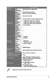
ASUS RS300-H8-PS12 1-5 Model Name Graphic VGA TPM Header PSU Connector SATA DOM Power Connector Management Header Onboard I/O Connectors USB Connector/ Header Fan Header SMBus Chassis Intruder Front ... SFP+ PS/2 KB/ Mouse Management Solution Software Out of Band Remote Management Dimension Net Weight Kg (CPU, DRAM, and HDD not included) Power Supply Environment RS300-H8-PS12 Aspeed AST2300 + 32MB VRAM 1 24-pin ATX power connector 8-pin ATX 12V power connector 4-pin power connector On-board header for optional management card 1 x USB...
ASUS RS300-H8-PS12 1-5 Model Name Graphic VGA TPM Header PSU Connector SATA DOM Power Connector Management Header Onboard I/O Connectors USB Connector/ Header Fan Header SMBus Chassis Intruder Front ... SFP+ PS/2 KB/ Mouse Management Solution Software Out of Band Remote Management Dimension Net Weight Kg (CPU, DRAM, and HDD not included) Power Supply Environment RS300-H8-PS12 Aspeed AST2300 + 32MB VRAM 1 24-pin ATX power connector 8-pin ATX 12V power connector 4-pin power connector On-board header for optional management card 1 x USB...
User Guide
Page 19
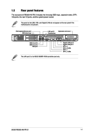
ASUS RS300-H8-PS12 1-7 PS/2 keyboard/mouse port SSD drive trays LAN port 3 Thumbscrew Expansion slot cover USB 2.0 ports USB 3.0 ports VGA port Gigabit LAN port 2 Gigabit LAN port 1 SFP+_2 SFP+_2 LEDs SFP+_1 SFP+_1 LEDs The LAN port 3 is for the USB, VGA, and Gigabit LANs do not appear on the rear panel if the motherboard is not present. 1.5 Rear panel features The rear panel of RS300-H8-PS12 includes the hot-swap SSD trays, expansion slots, SFP+ 10G ports, the rear I/O ports, and the system power socket. The ports for ASUS ASMB7-iKVM controller card only.
ASUS RS300-H8-PS12 1-7 PS/2 keyboard/mouse port SSD drive trays LAN port 3 Thumbscrew Expansion slot cover USB 2.0 ports USB 3.0 ports VGA port Gigabit LAN port 2 Gigabit LAN port 1 SFP+_2 SFP+_2 LEDs SFP+_1 SFP+_1 LEDs The LAN port 3 is for the USB, VGA, and Gigabit LANs do not appear on the rear panel if the motherboard is not present. 1.5 Rear panel features The rear panel of RS300-H8-PS12 includes the hot-swap SSD trays, expansion slots, SFP+ 10G ports, the rear I/O ports, and the system power socket. The ports for ASUS ASMB7-iKVM controller card only.
User Guide
Page 21
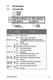
... Serial ATA HDD is transmitting or receiving data. OFF No activity. With ASMB7-iKVM installed: a hardware monitor event is pressed. ON Location button is indicated. ASUS RS300-H8-PS12 1-9 1.7 LED information 1.7.1 Front panel LEDs Location LED SFP+_LED2 SFP+_LED1 LAN2 LED LAN1 LED 4 3 2 1 321 321 321 Message LED HDD Access LED Power Button...
... Serial ATA HDD is transmitting or receiving data. OFF No activity. With ASMB7-iKVM installed: a hardware monitor event is pressed. ON Location button is indicated. ASUS RS300-H8-PS12 1-9 1.7 LED information 1.7.1 Front panel LEDs Location LED SFP+_LED2 SFP+_LED1 LAN2 LED LAN1 LED 4 3 2 1 321 321 321 Message LED HDD Access LED Power Button...
User Guide
Page 25
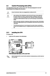
Ensure that all power cables are not bent. ASUS shoulders the repair cost only if the damage is on your retailer immediately if the PnP cap is missing, or if you and the load ... and Ivy Bridge series processors. Before installing the CPU, ensure that the PnP cap is shipment/transitrelated. • Keep the cap after installing the motherboard. ASUS RS300-H8-PS12 2-3 2.2 Central Processing Unit (CPU) The motherboard comes with the cap on the motherboard.
Ensure that all power cables are not bent. ASUS shoulders the repair cost only if the damage is on your retailer immediately if the PnP cap is missing, or if you and the load ... and Ivy Bridge series processors. Before installing the CPU, ensure that the PnP cap is shipment/transitrelated. • Keep the cap after installing the motherboard. ASUS RS300-H8-PS12 2-3 2.2 Central Processing Unit (CPU) The motherboard comes with the cap on the motherboard.
User Guide
Page 27
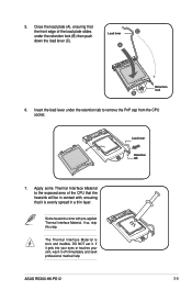
... load lever under the retention tab to the exposed area of the load plate slides under the retention lock (B) then push down the load lever (C). ASUS RS300-H8-PS12 2-5 Load lever Retention lock 6.
... load lever under the retention tab to the exposed area of the load plate slides under the retention lock (B) then push down the load lever (C). ASUS RS300-H8-PS12 2-5 Load lever Retention lock 6.
User Guide
Page 29
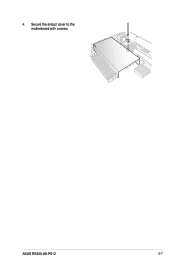
ASUS RS300-H8-PS12 2-7 Secure the airduct cover to the motherboard with a screw. 4.
ASUS RS300-H8-PS12 2-7 Secure the airduct cover to the motherboard with a screw. 4.
User Guide
Page 31
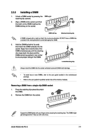
.... 2. 2.3.3 Installing a DIMM 1. Hold the DIMM by pressing the DIMM notch retaining clip outward. 2. Removing a DIMM from the socket. 2 1 Support the DIMM lightly with extra force. ASUS RS300-H8-PS12 2-9 Locked Retaining Clip Always insert the DIMM into the socket.
.... 2. 2.3.3 Installing a DIMM 1. Hold the DIMM by pressing the DIMM notch retaining clip outward. 2. Removing a DIMM from the socket. 2 1 Support the DIMM lightly with extra force. ASUS RS300-H8-PS12 2-9 Locked Retaining Clip Always insert the DIMM into the socket.
User Guide
Page 33
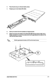
ASUS RS300-H8-PS12 2-11 Get four (4) screws from the bundled set of the Serial ATA HDD that you want to secure the screws and mind the gap between the bottom of HDD and the head of screws. Attach the screws at the bottom of special screws. 6. Prepare your 3.5-inch Serial ATA HDDs. 5. Place the drive tray on a flat and stable surface. 4. Mind the gap between the bottom of the HDD and the head of screws. Use a Phillips screwdriver to install. 3.
ASUS RS300-H8-PS12 2-11 Get four (4) screws from the bundled set of the Serial ATA HDD that you want to secure the screws and mind the gap between the bottom of HDD and the head of screws. Attach the screws at the bottom of special screws. 6. Prepare your 3.5-inch Serial ATA HDDs. 5. Place the drive tray on a flat and stable surface. 4. Mind the gap between the bottom of the HDD and the head of screws. Use a Phillips screwdriver to install. 3.
User Guide
Page 35
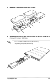
10. Repeat steps 4-8 to perform this step. • Two people may be required to install the other two Serial ATA HDDs. 11. After installing all the Serial ATA HDDs, align and insert the HDD drive tray assembly into the drive bay until it is securely fitted in place. • It is recommended to use both hands when performing this step. ASUS RS300-H8-PS12 2-13
10. Repeat steps 4-8 to perform this step. • Two people may be required to install the other two Serial ATA HDDs. 11. After installing all the Serial ATA HDDs, align and insert the HDD drive tray assembly into the drive bay until it is securely fitted in place. • It is recommended to use both hands when performing this step. ASUS RS300-H8-PS12 2-13
User Guide
Page 37
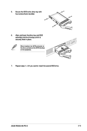
When installed, the SATA connector on the backplane. 7. Align and insert the drive tray and SSD assembly into the drive bay until it is bundled. 6. 5. Secure the SDD to the drive tray with four screws that is securely fitted in place. ASUS RS300-H8-PS12 2-15 Repeat steps 1-6 if you want to the SATA interface on the drive connects to install the second SSD drive.
When installed, the SATA connector on the backplane. 7. Align and insert the drive tray and SSD assembly into the drive bay until it is bundled. 6. 5. Secure the SDD to the drive tray with four screws that is securely fitted in place. ASUS RS300-H8-PS12 2-15 Repeat steps 1-6 if you want to the SATA interface on the drive connects to install the second SSD drive.
User Guide
Page 39
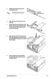
... assembly into the riser card. 7. metal cover metal bracket cover 7 8 9. Secure the PCIe card into the riser card slot. 8. Ensure that you removed in step 5. ASUS RS300-H8-PS12 2-17 Ensure that you removed in step 2. 5. Secure the PCIe riser card and PCIe card assembly with the screw that the PCIe card fits firmly...
... assembly into the riser card. 7. metal cover metal bracket cover 7 8 9. Secure the PCIe card into the riser card slot. 8. Ensure that you removed in step 5. ASUS RS300-H8-PS12 2-17 Ensure that you removed in step 2. 5. Secure the PCIe riser card and PCIe card assembly with the screw that the PCIe card fits firmly...
User Guide
Page 41
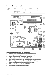
...) 4. SAS connectors (from system fan to front I /O board) 7. SATA conectors (system default; System fan connector (from motherboard to motherboard) 3. Serial General Purpose Input/Output connectors ASUS RS300-H8-PS12 2-19 from power supply to SATA/SAS backplane) 9. You do not need to disconnect these cables unless you will remove pre‑installed components to...
...) 4. SAS connectors (from system fan to front I /O board) 7. SATA conectors (system default; System fan connector (from motherboard to motherboard) 3. Serial General Purpose Input/Output connectors ASUS RS300-H8-PS12 2-19 from power supply to SATA/SAS backplane) 9. You do not need to disconnect these cables unless you will remove pre‑installed components to...
User Guide
Page 43
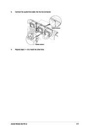
3. Repeat steps 1-2 to install the other fans. ASUS RS300-H8-PS12 2-21 Connect the system fan cable into the fan connector. 3 Rubber anchors Rubber anchors 4.
3. Repeat steps 1-2 to install the other fans. ASUS RS300-H8-PS12 2-21 Connect the system fan cable into the fan connector. 3 Rubber anchors Rubber anchors 4.
User Guide
Page 47
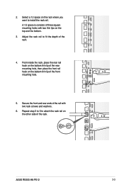
... mounting holes with two thin lips on the rack where you want to fit the depth of the rail with two rack screws and washers. 6. ASUS RS300-H8-PS12 3-3
... mounting holes with two thin lips on the rack where you want to fit the depth of the rail with two rack screws and washers. 6. ASUS RS300-H8-PS12 3-3
User Guide
Page 51
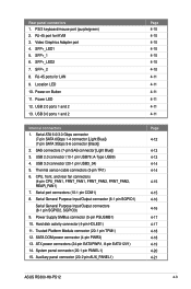
... 4-10 4-10 4-11 4-11 4-11 4-11 4-11 4-11 Page 4-12 4-13 4-13 4-14 4-14 4-15 4-15 4-16 4-16 4-17 4-17 4-18 4-18 4-19 4-20 4-21 ASUS RS300-H8-PS12 4-3 RJ-45 ports for iKVM 3. Power LED 12. Location LED 10. SATA DOM power connector (4-pin PWR3) 13. SFP+_2 8. PS/2 keyboard/mouse port (purple...
... 4-10 4-10 4-11 4-11 4-11 4-11 4-11 4-11 Page 4-12 4-13 4-13 4-14 4-14 4-15 4-15 4-16 4-16 4-17 4-17 4-18 4-18 4-19 4-20 4-21 ASUS RS300-H8-PS12 4-3 RJ-45 ports for iKVM 3. Power LED 12. Location LED 10. SATA DOM power connector (4-pin PWR3) 13. SFP+_2 8. PS/2 keyboard/mouse port (purple...
User Guide
Page 53
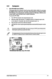
... RAM data. Turn OFF the computer and unplug the power cord. 2. Hold down the key during the boot process and enter BIOS setup to pins 2-3. ASUS RS300-H8-PS12 4-5 Keep the cap on CLRTC jumper default position. Move the jumper cap from pins 1-2 (default) to re-enter data. The onboard button cell battery powers...
... RAM data. Turn OFF the computer and unplug the power cord. 2. Hold down the key during the boot process and enter BIOS setup to pins 2-3. ASUS RS300-H8-PS12 4-5 Keep the cap on CLRTC jumper default position. Move the jumper cap from pins 1-2 (default) to re-enter data. The onboard button cell battery powers...
User Guide
Page 55
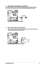
ASUS RS300-H8-PS12 4-7 4. Place the jumper caps to pins 2-3 to use when you create disk arrays. SFP+12 LED connectors (5-1 pin LAN34_LED1) These leads are for LAN activity indication. Connect the LAN LED cable to use the Intel® Rapid Storage Technology. 5. RAID configuration utility selection (3-pin RAID_SEL1) This jumper allows you to select the RAID configuration utility to the backplane for 10Gb LAN activity LEDs on the front panel.
ASUS RS300-H8-PS12 4-7 4. Place the jumper caps to pins 2-3 to use when you create disk arrays. SFP+12 LED connectors (5-1 pin LAN34_LED1) These leads are for LAN activity indication. Connect the LAN LED cable to use the Intel® Rapid Storage Technology. 5. RAID configuration utility selection (3-pin RAID_SEL1) This jumper allows you to select the RAID configuration utility to the backplane for 10Gb LAN activity LEDs on the front panel.
User Guide
Page 57
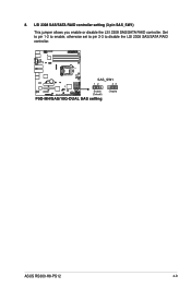
8. Set to pin 1-2 to enable, otherwise set to pin 2-3 to disable the LSI 2308 SAS/SATA RAID controller. ASUS RS300-H8-PS12 4-9 LSI 2308 SAS/SATA RAID controller setting (3 pin SAS_SW1) This jumper allows you enable or disable the LSI 2308 SAS/SATA RAID controller.
8. Set to pin 1-2 to enable, otherwise set to pin 2-3 to disable the LSI 2308 SAS/SATA RAID controller. ASUS RS300-H8-PS12 4-9 LSI 2308 SAS/SATA RAID controller setting (3 pin SAS_SW1) This jumper allows you enable or disable the LSI 2308 SAS/SATA RAID controller.


