
User Guide
Page 4
... 4-2 4.2 Jumpers 4-4 4.3 Connectors 4-9 Chapter 5: BIOS setup 5.1 Managing and updating your BIOS 5-2 5.1.1 Creating a bootable floppy disk 5-2 5.1.2 AFUDOS utility 5-3 5.1.3 ASUS CrashFree BIOS 2 utility 5-6 5.1.4 ASUS Update utility 5-8 5.2 BIOS setup program 5-11 5.2.1 BIOS menu screen 5-12 5.2.2 Menu bar 5-12 5.2.3 Navigation keys 5-12 5.2.4 Menu items 5-13 5.2.5 Sub-menu items 5-13 5.2.6 Configuration fields 5-13 5.2.7 Pop-up window 5-13 5.2.8 Scroll bar...
... 4-2 4.2 Jumpers 4-4 4.3 Connectors 4-9 Chapter 5: BIOS setup 5.1 Managing and updating your BIOS 5-2 5.1.1 Creating a bootable floppy disk 5-2 5.1.2 AFUDOS utility 5-3 5.1.3 ASUS CrashFree BIOS 2 utility 5-6 5.1.4 ASUS Update utility 5-8 5.2 BIOS setup program 5-11 5.2.1 BIOS menu screen 5-12 5.2.2 Menu bar 5-12 5.2.3 Navigation keys 5-12 5.2.4 Menu items 5-13 5.2.5 Sub-menu items 5-13 5.2.6 Configuration fields 5-13 5.2.7 Pop-up window 5-13 5.2.8 Scroll bar...
User Guide
Page 10
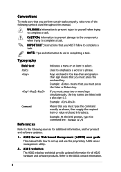
... and software products. I N G : Information to prevent injury to yourself when trying to select. N O T E : Tips and information to the ASUS contact information. Example: means that you must press two or more keys simultaneously, the key names are linked with a plus sign (+). Refer to aid in brackets. x W A R N I M P O R T A N T : Instructions that you must press the Enter or...
... and software products. I N G : Information to prevent injury to yourself when trying to select. N O T E : Tips and information to the ASUS contact information. Example: means that you must press two or more keys simultaneously, the key names are linked with a plus sign (+). Refer to aid in brackets. x W A R N I M P O R T A N T : Instructions that you must press the Enter or...
User Guide
Page 21
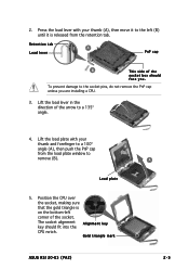
... from the load plate window to the socket pins, do not remove the PnP cap unless you . The socket alignment A l i g n m e n t k e y key should face you are installing a CPU. 3. Gold triangle mark ASUS RS120-E3 (PA2) A 2-5 Retention tab A Load lever PnP cap B This side of the socket box should fit into the CPU notch. To prevent damage...
... from the load plate window to the socket pins, do not remove the PnP cap unless you . The socket alignment A l i g n m e n t k e y key should face you are installing a CPU. 3. Gold triangle mark ASUS RS120-E3 (PA2) A 2-5 Retention tab A Load lever PnP cap B This side of the socket box should fit into the CPU notch. To prevent damage...
User Guide
Page 25
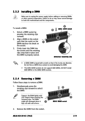
...: 1. Do not force a DIMM into the socket until the retaining clips snap back in only one direction. Support the DIMM lightly with extra force. 2. ASUS RS120-E3 (PA2) 2 1 DDR2 DIMM notch 2-9 The DIMM might get damaged when it fits in place and the DIMM is properly seated. 2 3 DDR2 DIMM notch Unlocked... retaining clip • A DDR2 DIMM is keyed with a notch so that the notch on the 1 DIMM matches the break on the socket such that it 1 flips out with your fingers when...
...: 1. Do not force a DIMM into the socket until the retaining clips snap back in only one direction. Support the DIMM lightly with extra force. 2. ASUS RS120-E3 (PA2) 2 1 DDR2 DIMM notch 2-9 The DIMM might get damaged when it fits in place and the DIMM is properly seated. 2 3 DDR2 DIMM notch Unlocked... retaining clip • A DDR2 DIMM is keyed with a notch so that the notch on the 1 DIMM matches the break on the socket such that it 1 flips out with your fingers when...
User Guide
Page 50
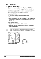
... the CMOS RTC RAM data. Keep the cap on CLRTC jumper default position. To erase the RTC RAM: 1. Remove the onboard battery. 3. Hold down the key during the boot process and enter BIOS setup to pins 2-3. Except when clearing the RTC RAM, never remove the cap on pins 2-3 for about 5~10...
... the CMOS RTC RAM data. Keep the cap on CLRTC jumper default position. To erase the RTC RAM: 1. Remove the onboard battery. 3. Hold down the key during the boot process and enter BIOS setup to pins 2-3. Except when clearing the RTC RAM, never remove the cap on pins 2-3 for about 5~10...
User Guide
Page 51
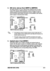
... a power supply that can provide 500mA on the +5VSB lead for each USB port; Keyboard power (3-pin KBPWR1) This jumper allows you press a key on the +5VSB lead, and a corresponding setting in sleep mode. 3. Set this jumper to pins 2-3 (+5VSB) to wake up the computer when... capability (+5VSB) whether under normal condition or in the BIOS. ® P5MT-R KBPWR1 1 2 +5V (Default) 2 3 +5VSB P5MT-R Keyboard power setting ASUS RS120-E3 (PA2) 4-5 This feature requires an ATX power supply that can supply at least 1A on the keyboard (the default is the Space Bar). otherwise, the system...
... a power supply that can provide 500mA on the +5VSB lead for each USB port; Keyboard power (3-pin KBPWR1) This jumper allows you press a key on the +5VSB lead, and a corresponding setting in sleep mode. 3. Set this jumper to pins 2-3 (+5VSB) to wake up the computer when... capability (+5VSB) whether under normal condition or in the BIOS. ® P5MT-R KBPWR1 1 2 +5V (Default) 2 3 +5VSB P5MT-R Keyboard power setting ASUS RS120-E3 (PA2) 4-5 This feature requires an ATX power supply that can supply at least 1A on the keyboard (the default is the Space Bar). otherwise, the system...
User Guide
Page 75
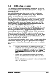
...a d S e t u p D e f a u l t s item under the Exit Menu. Press during the Power-On-Self-Test (POST) to "Run Setup". ASUS RS120-E3 (PA2) 5-11 5.2 BIOS setup program This motherboard supports a programmable firmware chip that the computer can recognize these changes and record them in the CMOS RAM of...asus.com) to run this program. otherwise, POST continues with the opportunity to download the latest BIOS file for reference purposes only, and may not exactly match what you scroll through the various sub-menus and make your selections from the available options using the navigation keys...
...a d S e t u p D e f a u l t s item under the Exit Menu. Press during the Power-On-Self-Test (POST) to "Run Setup". ASUS RS120-E3 (PA2) 5-11 5.2 BIOS setup program This motherboard supports a programmable firmware chip that the computer can recognize these changes and record them in the CMOS RAM of...asus.com) to run this program. otherwise, POST continues with the opportunity to download the latest BIOS file for reference purposes only, and may not exactly match what you scroll through the various sub-menus and make your selections from the available options using the navigation keys...
User Guide
Page 76
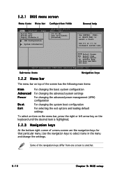
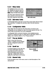
Change Option F1 General Help F10 Save and Exit ESC Exit v02.57 (C)Copyright 1985-2004, American Megatrends, Inc. Sub-menu items Navigation keys 5.2.2 Menu bar The menu bar on top of the screen has the following main items: Main Advanced Power Boot Exit For changing the basic system... default settings To select an item on the menu bar, press the right or left arrow key on the keyboard until the desired item is highlighted. 5.2.3 Navigation keys At the bottom right corner of the navigation keys differ from one screen to configure system time. Some of a menu screen are the navigation...
Change Option F1 General Help F10 Save and Exit ESC Exit v02.57 (C)Copyright 1985-2004, American Megatrends, Inc. Sub-menu items Navigation keys 5.2.2 Menu bar The menu bar on top of the screen has the following main items: Main Advanced Power Boot Exit For changing the basic system... default settings To select an item on the menu bar, press the right or left arrow key on the keyboard until the desired item is highlighted. 5.2.3 Navigation keys At the bottom right corner of the navigation keys differ from one screen to configure system time. Some of a menu screen are the navigation...
User Guide
Page 77
... bar displays the specific items for that menu. Press the Up/Down arrow keys or / keys to display a list of a menu screen when there are items that do not fit on any menu screen means that is highlighted when selected. ASUS RS120-E3 (PA2) 5-13 Advanced APM Configuration Power Management/APM Video Power Down Mode Hard...
... bar displays the specific items for that menu. Press the Up/Down arrow keys or / keys to display a list of a menu screen when there are items that do not fit on any menu screen means that is highlighted when selected. ASUS RS120-E3 (PA2) 5-13 Advanced APM Configuration Power Management/APM Video Power Down Mode Hard...
User Guide
Page 84
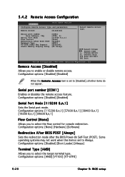
... and parameters Remote Access [Disabled] Serial port number Base Address, IRQ Serial Port Mode Flow Control Redirection After BIOS POST Terminal Type VT-UTFB Combo Key Support Sredir Memory Display Delay [COM1] [3F8h, 4] [115200 8,n,1] [None] [Always] [ANSI] [Enabled] [No Delay] Select Remote Access type. Change Option F1 General Help F10 Save...
... and parameters Remote Access [Disabled] Serial port number Base Address, IRQ Serial Port Mode Flow Control Redirection After BIOS POST Terminal Type VT-UTFB Combo Key Support Sredir Memory Display Delay [COM1] [3F8h, 4] [115200 8,n,1] [None] [Always] [ANSI] [Enabled] [No Delay] Select Remote Access type. Change Option F1 General Help F10 Save...
User Guide
Page 85
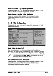
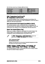
... or < - > keys to the CPU documentation for details. Refer to adjust the values. Configuration options: [Disabled] [Enabled] Sredir Memory Display Delay [No Delay] Allows you installed an unlocked CPU. Configuration options: [ 8]...[28] You can only adjust the R a t i o C M O S if you to set in this item. Configuration options: [Disabled] [Enabled] ASUS RS120-E3 (PA2) 5-21 Configuration..., American Megatrends, Inc. Ratio CMOS Setting [16] Sets the ratio between CPU Core Clock and the FSB Frequency. VT-UTF8 Combo Key Support [Enabled] Enables or disables the VT-UTF8 combo...
... or < - > keys to the CPU documentation for details. Refer to adjust the values. Configuration options: [Disabled] [Enabled] Sredir Memory Display Delay [No Delay] Allows you installed an unlocked CPU. Configuration options: [ 8]...[28] You can only adjust the R a t i o C M O S if you to set in this item. Configuration options: [Disabled] [Enabled] ASUS RS120-E3 (PA2) 5-21 Configuration..., American Megatrends, Inc. Ratio CMOS Setting [16] Sets the ratio between CPU Core Clock and the FSB Frequency. VT-UTF8 Combo Key Support [Enabled] Enables or disables the VT-UTF8 combo...
User Guide
Page 96
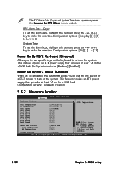
...lead. Configuration options: [00] [1]... ~ [23] Power On By PS/2 Keyboard [Disabled] Allows you to use specific keys on the keyboard to make the selection. Configuration options: [Disabled] [Enabled] 5.5.2 Hardware Monitor Power BIOS SETUP UTILITY Hardware Monitor...[060] [050] [ 1.236V] Select Screen Select Item +- Configuration options: [Everyday] [1] [2] [3]... ~ [31] System Time To set to [Enabled], this item and press the or key to turn on the +5VSB lead. Change Option F1 General Help F10 Save and Exit ESC Exit v02.58 (C)Copyright 1985-2004, American Megatrends, Inc...
...lead. Configuration options: [00] [1]... ~ [23] Power On By PS/2 Keyboard [Disabled] Allows you to use specific keys on the keyboard to make the selection. Configuration options: [Disabled] [Enabled] 5.5.2 Hardware Monitor Power BIOS SETUP UTILITY Hardware Monitor...[060] [050] [ 1.236V] Select Screen Select Item +- Configuration options: [Everyday] [1] [2] [3]... ~ [31] System Time To set to [Enabled], this item and press the or key to turn on the +5VSB lead. Change Option F1 General Help F10 Save and Exit ESC Exit v02.58 (C)Copyright 1985-2004, American Megatrends, Inc...
User Guide
Page 97
... Fan] [Smart Fan II] The C P U 1 T e m p e r a t u r e and M B T e m p e r a t u r e items do not wish to enable or disable the ASUS Smart Fan Control feature that smartly adjusts the fan speeds for more efficient system operation. ASUS RS120-E3 (PA2) 5-33 Use the down arrow key to the connector on the motherboard, the field shows N/A. CPU1 Temperature [XXX] MB Temperature [XXX...
... Fan] [Smart Fan II] The C P U 1 T e m p e r a t u r e and M B T e m p e r a t u r e items do not wish to enable or disable the ASUS Smart Fan Control feature that smartly adjusts the fan speeds for more efficient system operation. ASUS RS120-E3 (PA2) 5-33 Use the down arrow key to the connector on the motherboard, the field shows N/A. CPU1 Temperature [XXX] MB Temperature [XXX...
User Guide
Page 99
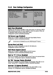
...system. Configuration options: [Off] [On] PS/2 Mouse Support [Auto] Allows you to enable or disable support for the F1 key to trap Interrupt 19. When set to [Enabled], this function allows the option ROMs to be pressed when error occurs. Configuration ...to Enabled, the system displays the message "Press DEL to use the ASUS MyLogo2™ feature. Configuration options: [Disabled] [Enabled] [Auto] Wait for the NumLock. Configuration options: [Disabled] [Enabled] ASUS RS120-E3 (PA2) 5-35 5.6.2 Boot Settings Configuration BIOS SETUP UTILITY Boot Boot Settings Configuration ...
...system. Configuration options: [Off] [On] PS/2 Mouse Support [Auto] Allows you to enable or disable support for the F1 key to trap Interrupt 19. When set to [Enabled], this function allows the option ROMs to be pressed when error occurs. Configuration ...to Enabled, the system displays the message "Press DEL to use the ASUS MyLogo2™ feature. Configuration options: [Disabled] [Enabled] [Auto] Wait for the NumLock. Configuration options: [Disabled] [Enabled] ASUS RS120-E3 (PA2) 5-35 5.6.2 Boot Settings Configuration BIOS SETUP UTILITY Boot Boot Settings Configuration ...
User Guide
Page 103
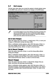
...changes that you made changes to any of the options from this menu to exit the Setup utility without saving your changes and exit Setup. ASUS RS120-E3 (PA2) 5-39 Exit & Discard Changes Select this option then press to exit. Select one of the settings in the menus, pressing does not ...select [OK] then press to save or discard your changes and exit Setup. If you made , and restore the previously saved settings. F10 key can be used for the BIOS items, and save your changes to the BIOS items. Main Advanced Exit Options BIOS SETUP UTILITY Security Boot Exit...
...changes that you made changes to any of the options from this menu to exit the Setup utility without saving your changes and exit Setup. ASUS RS120-E3 (PA2) 5-39 Exit & Discard Changes Select this option then press to exit. Select one of the settings in the menus, pressing does not ...select [OK] then press to save or discard your changes and exit Setup. If you made , and restore the previously saved settings. F10 key can be used for the BIOS items, and save your changes to the BIOS items. Main Advanced Exit Options BIOS SETUP UTILITY Security Boot Exit...
User Guide
Page 108
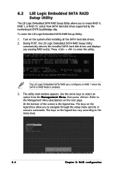
...is enabled. 3. Refer to the Management Menu descriptions on the legend box vary according to the menu level. 6-4 Chapter 6: RAID configuration The keys on the next page. 6.2 LSI Logic Embedded SATA RAID Setup Utility The LSI Logic Embedded SATA RAID Setup Utility allows you to navigate through... the setup menu options or execute commands. Use the arrow keys to enter the utility. Press + to select an option from SATA hard disk drives supported by the motherboard ICH7R Southbridge chip. To...
...is enabled. 3. Refer to the Management Menu descriptions on the legend box vary according to the menu level. 6-4 Chapter 6: RAID configuration The keys on the next page. 6.2 LSI Logic Embedded SATA RAID Setup Utility The LSI Logic Embedded SATA RAID Setup Utility allows you to navigate through... the setup menu options or execute commands. Use the arrow keys to enter the utility. Press + to select an option from SATA hard disk drives supported by the motherboard ICH7R Southbridge chip. To...
User Guide
Page 109
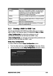
... E a s y C o n f i g u r a t i o n option: 1. Using Easy Configuration To create a RAID set automatically including the size and stripe size (RAID 1 only). ASUS RS120-E3 (PA2) 6-5 In N e w C o n f i g u r a t i o n, you to check the data consistency of the logical drives of configurations: E a s y and N e w....f i g u r a t i o n, the logical drive parameters are set using the Easy Configuration or the New Configuration command. Use the arrow keys to create RAID 0 or RAID 1 set size and stripe size (RAID 1 only). From the utility main menu, highlight C o n f i g u r e, then ...
... E a s y C o n f i g u r a t i o n option: 1. Using Easy Configuration To create a RAID set automatically including the size and stripe size (RAID 1 only). ASUS RS120-E3 (PA2) 6-5 In N e w C o n f i g u r a t i o n, you to check the data consistency of the logical drives of configurations: E a s y and N e w....f i g u r a t i o n, the logical drive parameters are set using the Easy Configuration or the New Configuration command. Use the arrow keys to create RAID 0 or RAID 1 set size and stripe size (RAID 1 only). From the utility main menu, highlight C o n f i g u r e, then ...
User Guide
Page 112
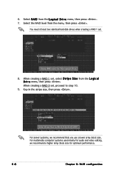
For multimedia computer systems used mainly for optimum performance. 6-8 Chapter 6: RAID configuration Select R A I D from the menu, then press . Key-in the stripe size, then press . 6. You need at least two identical hard disk drives when creating a RAID 1 set , proceed to step 10. 9. Select the ...
For multimedia computer systems used mainly for optimum performance. 6-8 Chapter 6: RAID configuration Select R A I D from the menu, then press . Key-in the stripe size, then press . 6. You need at least two identical hard disk drives when creating a RAID 1 set , proceed to step 10. 9. Select the ...
User Guide
Page 114
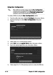
Follow steps 3 to 7 of the previous section to 13 of the previous section. 4. Key-in the desired logical drive size, then press . 6. To create a RAID set is already existing, using the N e w C o n f i g u r a t i o n option: 1. Using New Configuration When a RAID set using ... the existing RAID set . 6-10 Chapter 6: RAID configuration Select S i z e from the L o g i c a l D r i v e menu, then press . 5. From the utility main menu, highlight C o n f i g u r e, then press . 2. Use the arrow keys to view or create another RAID configuration.
Follow steps 3 to 7 of the previous section to 13 of the previous section. 4. Key-in the desired logical drive size, then press . 6. To create a RAID set is already existing, using the N e w C o n f i g u r a t i o n option: 1. Using New Configuration When a RAID set using ... the existing RAID set . 6-10 Chapter 6: RAID configuration Select S i z e from the L o g i c a l D r i v e menu, then press . 5. From the utility main menu, highlight C o n f i g u r e, then press . 2. Use the arrow keys to view or create another RAID configuration.

User Guide
Page 115
... to select Easy Configuration, then press . 3. From the utility main menu, highlight C o n f i g u r e, then press . 2. Use the arrow keys to the SATA ports. Select the drive(s) you want to ONLIN A[X]-[Y], where X is the array number, and Y is the drive number. When selected, the drive ...A D Y to include in the RAID set, then press . The information of the selected hard disk drive displays at the bottom of the screen. ASUS RS120-E3 (PA2) 6-11 To create a RAID 10 set using four identical hard disk drives. 6.2.2 Creating a RAID 10 set You can create a RAID 10 set using...
... to select Easy Configuration, then press . 3. From the utility main menu, highlight C o n f i g u r e, then press . 2. Use the arrow keys to the SATA ports. Select the drive(s) you want to ONLIN A[X]-[Y], where X is the array number, and Y is the drive number. When selected, the drive ...A D Y to include in the RAID set, then press . The information of the selected hard disk drive displays at the bottom of the screen. ASUS RS120-E3 (PA2) 6-11 To create a RAID 10 set using four identical hard disk drives. 6.2.2 Creating a RAID 10 set You can create a RAID 10 set using...