

User Guide
Page 5
... CPU Configuration 5-21 5.4.4 Chipset Configuration 5-23 5.4.5 Onboard Devices Configuration 5-27 5.4.6 PCI/PnP Configuration 5-28 5.5 Power menu 5-29 5.5.1 APM Configuration 5-30 5.5.2 Hardware Monitor 5-32 5.6 Boot menu 5-34 5.6.1 Boot Device Priority 5-34 5.6.2 Boot Settings Configuration 5-35 5.6.3 Security 5-36 5.7 Exit menu 5-39 Chapter 6: RAID configuration 6.1 Setting up RAID 6-2 6.1.1 RAID definitions 6-2 6.1.2 Installing hard disk drives 6-3 6.1.3 Setting the RAID item in BIOS 6-3 6.1.4 RAID configuration utility 6-3 6.2 LSI Logic Embedded SATA RAID Setup Utility...
... CPU Configuration 5-21 5.4.4 Chipset Configuration 5-23 5.4.5 Onboard Devices Configuration 5-27 5.4.6 PCI/PnP Configuration 5-28 5.5 Power menu 5-29 5.5.1 APM Configuration 5-30 5.5.2 Hardware Monitor 5-32 5.6 Boot menu 5-34 5.6.1 Boot Device Priority 5-34 5.6.2 Boot Settings Configuration 5-35 5.6.3 Security 5-36 5.7 Exit menu 5-39 Chapter 6: RAID configuration 6.1 Setting up RAID 6-2 6.1.1 RAID definitions 6-2 6.1.2 Installing hard disk drives 6-3 6.1.3 Setting the RAID item in BIOS 6-3 6.1.4 RAID configuration utility 6-3 6.2 LSI Logic Embedded SATA RAID Setup Utility...
User Guide
Page 9
... motherboard layout, jumper settings, and connector locations. 5. ix Chapter 4: Motherboard information This chapter gives information about the motherboard that comes with at least basic knowledge of configuring a server. Detailed descriptions of the server, including sections on front panel and rear panel specifications. 2. Chapter 1: Product Introduction This chapter describes the general features of the BIOS parameters are also provided. 7 Chapter 7: Driver installation This chapter provides instructions for installing the necessary drivers...
... motherboard layout, jumper settings, and connector locations. 5. ix Chapter 4: Motherboard information This chapter gives information about the motherboard that comes with at least basic knowledge of configuring a server. Detailed descriptions of the server, including sections on front panel and rear panel specifications. 2. Chapter 1: Product Introduction This chapter describes the general features of the BIOS parameters are also provided. 7 Chapter 7: Driver installation This chapter provides instructions for installing the necessary drivers...

User Guide
Page 13
...® Matrix Storage Manager - RAID 0, RAID 1, RAID 10, or software RAID 5 configuration using the LSI Logic Embedded SATA RAID controller Management ASUS Server Web-based Management (ASWM) Monitoring Voltage, temperature, and fan speed monitoring Automatic System Restart (ASR) feature P o w e r r e q u i r e m e n t 400 W power supply, 100V~240V, 50Hz~60Hz Dimensions 600 mm (l) x 445 mm (w) x 43.6 mm (h) ASUS RS120-E3 (PA2) 1-3 1.2 System specifications The ASUS RS120-E3 (PA2) is a 1U barebone server system featuring the ASUS P5MT-R motherboard. The server supports the Intel...
...® Matrix Storage Manager - RAID 0, RAID 1, RAID 10, or software RAID 5 configuration using the LSI Logic Embedded SATA RAID controller Management ASUS Server Web-based Management (ASWM) Monitoring Voltage, temperature, and fan speed monitoring Automatic System Restart (ASR) feature P o w e r r e q u i r e m e n t 400 W power supply, 100V~240V, 50Hz~60Hz Dimensions 600 mm (l) x 445 mm (w) x 43.6 mm (h) ASUS RS120-E3 (PA2) 1-3 1.2 System specifications The ASUS RS120-E3 (PA2) is a 1U barebone server system featuring the ASUS P5MT-R motherboard. The server supports the Intel...
User Guide
Page 15
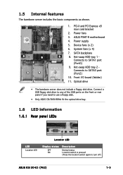
...a USB floppy disk drive to any of the USB ports on the front or rear panel if you need to use a floppy disk. • Only ASUS CD/DVD-ROMs fit the optical drive bay. 1.6 LED information 1.6.1 Rear panel LEDs LED Location LED Location LED Display status OFF ON Description Normal status Location switch is pressed (Press the location switch again to SATA1 port (Port0) 9. ASUS P5MT-R motherboard 4. Connects to turn off) ASUS RS120-E3 (PA2) 1-5 Hot-swap HDD tray 2 Connects to SATA3 port (Port2) 10. PCI-X and PCI Express x8 riser card bracket 2. Device fans (x 2) 6. SATA backplane...
...a USB floppy disk drive to any of the USB ports on the front or rear panel if you need to use a floppy disk. • Only ASUS CD/DVD-ROMs fit the optical drive bay. 1.6 LED information 1.6.1 Rear panel LEDs LED Location LED Location LED Display status OFF ON Description Normal status Location switch is pressed (Press the location switch again to SATA1 port (Port0) 9. ASUS P5MT-R motherboard 4. Connects to turn off) ASUS RS120-E3 (PA2) 1-5 Hot-swap HDD tray 2 Connects to SATA3 port (Port2) 10. PCI-X and PCI Express x8 riser card bracket 2. Device fans (x 2) 6. SATA backplane...
User Guide
Page 31
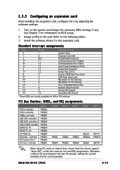
... Communications Port (COM2) Communications Port (COM1) Sound Card (sometimes LPT2) Floppy Disk Controller Printer Port (LPT1) System CMOS/Real Time Clock ACPI Mode when used IRQ Holder for PCI Steering IRQ Holder for PCI Steering PS/2 Compatible Mouse Port Numeric Data Processor Primary IDE Channel Secondary IDE Channel *These IRQs are usually available for the expansion card. See Chapter 5 for information on shared slots, ensure that the drivers support...
... Communications Port (COM2) Communications Port (COM1) Sound Card (sometimes LPT2) Floppy Disk Controller Printer Port (LPT1) System CMOS/Real Time Clock ACPI Mode when used IRQ Holder for PCI Steering IRQ Holder for PCI Steering PS/2 Compatible Mouse Port Numeric Data Processor Primary IDE Channel Secondary IDE Channel *These IRQs are usually available for the expansion card. See Chapter 5 for information on shared slots, ensure that the drivers support...

User Guide
Page 55
... signal cable. This prevents incorrect insertion when you connect the IDE cable. ® P5MT-R P5MT-R IDE connector ASUS RS120-E3 (PA2) PRI_IDE1 PIN 1 NOTE: Orient the red markings (usually zigzag) on the Ultra ATA cable connector. You must configure the optical drive as master/slave device by setting its jumper accordingly. 4.3 Connectors 1 . IDE connector (40-1 pin PRI_IDE1) This connector is for the jumper settings. Insert one end of the floppy disk drive.
... signal cable. This prevents incorrect insertion when you connect the IDE cable. ® P5MT-R P5MT-R IDE connector ASUS RS120-E3 (PA2) PRI_IDE1 PIN 1 NOTE: Orient the red markings (usually zigzag) on the Ultra ATA cable connector. You must configure the optical drive as master/slave device by setting its jumper accordingly. 4.3 Connectors 1 . IDE connector (40-1 pin PRI_IDE1) This connector is for the jumper settings. Insert one end of the floppy disk drive.

User Guide
Page 56
...can create a RAID 0, RAID 1, RAID 10, and software RAID 5 configuration using the Intel® Matrix Storage Manager, or RAID 0, RAID 1, and RAID 10 configuration using the LSI Logic Embedded SATA RAID utility in the Intel® ICH7R Southbridge. If you can connect Serial ATA boot/data hard disk drives to [RAID]. These connectors are for the Serial ATA signal cables for the recommended SATA hard disk drive connections. 3. If you installed Serial ATA hard disk drives, you intend to create a Serial ATA RAID set using the connectors in the BIOS to these connectors, set to the...
...can create a RAID 0, RAID 1, RAID 10, and software RAID 5 configuration using the Intel® Matrix Storage Manager, or RAID 0, RAID 1, and RAID 10 configuration using the LSI Logic Embedded SATA RAID utility in the Intel® ICH7R Southbridge. If you can connect Serial ATA boot/data hard disk drives to [RAID]. These connectors are for the Serial ATA signal cables for the recommended SATA hard disk drive connections. 3. If you installed Serial ATA hard disk drives, you intend to create a Serial ATA RAID set using the connectors in the BIOS to these connectors, set to the...

User Guide
Page 79
... Slave BIOS SETUP UTILITY [Enhanced] [IDE] : [Not Detected] : [Not Detected] : [Not Detected] : [Not Detected] : [Not Detected] : [Not Detected] Options Disabled Compatible Enhanced IDE Detect Time Out (Sec) [35] Select Screen Select Item +- Configure SATA As [IDE] Sets the configuration for details. supported on the installed operating system (OS). ASUS RS120-E3 (PA2) 5-15 ATA/IDE Configuration [Enhanced] Allows selection of the IDE operation mode depending on Windows® 2000/2003 Server/XP). Windows® Server 2000/2003. Set to [Compatible] mode...
... Slave BIOS SETUP UTILITY [Enhanced] [IDE] : [Not Detected] : [Not Detected] : [Not Detected] : [Not Detected] : [Not Detected] : [Not Detected] Options Disabled Compatible Enhanced IDE Detect Time Out (Sec) [35] Select Screen Select Item +- Configure SATA As [IDE] Sets the configuration for details. supported on the installed operating system (OS). ASUS RS120-E3 (PA2) 5-15 ATA/IDE Configuration [Enhanced] Allows selection of the IDE operation mode depending on Windows® 2000/2003 Server/XP). Windows® Server 2000/2003. Set to [Compatible] mode...

User Guide
Page 80
... to internally optimize the order of commands. Configuration options: • [SATA Only] - If you set the A T A/ IDE Configuration item to [AHCI]. IDE Detect Time Out (Sec) [35] Selects the time our value (in seconds) for detecting ATA/ATAPI devices. Configuration options: [0] [5] [10] [15] [20] [25] [30] [35] 5-16 Chapter 5: BIOS setup Configuration options: [Disabled] [Enabled] The O n b o a r d S A T A R A I D E C h a n n e l s option appears only when you want the Serial ATA hard disk drives to use...
... to internally optimize the order of commands. Configuration options: • [SATA Only] - If you set the A T A/ IDE Configuration item to [AHCI]. IDE Detect Time Out (Sec) [35] Selects the time our value (in seconds) for detecting ATA/ATAPI devices. Configuration options: [0] [5] [10] [15] [20] [25] [30] [35] 5-16 Chapter 5: BIOS setup Configuration options: [Disabled] [Enabled] The O n b o a r d S A T A R A I D E C h a n n e l s option appears only when you want the Serial ATA hard disk drives to use...

User Guide
Page 81
... are not user-configurable. Configuration options: [Not Installed] [Auto] [CDROM] [ARMD] LBA/Large Mode [Auto] Enables or disables the LBA mode. Configuration options: [Disabled] [Auto] ASUS RS120-E3 (PA2) 5-17 Change Option F1 General Help F10 Save and Exit ESC Exit v02.58 (C)Copyright 1985-2004, American Megatrends, Inc. When set to [Auto], the data transfer from and to the system. These values are specifically configuring a CD-ROM drive. Configuration options: [Disabled] [Auto...
... are not user-configurable. Configuration options: [Not Installed] [Auto] [CDROM] [ARMD] LBA/Large Mode [Auto] Enables or disables the LBA mode. Configuration options: [Disabled] [Auto] ASUS RS120-E3 (PA2) 5-17 Change Option F1 General Help F10 Save and Exit ESC Exit v02.58 (C)Copyright 1985-2004, American Megatrends, Inc. When set to [Auto], the data transfer from and to the system. These values are specifically configuring a CD-ROM drive. Configuration options: [Disabled] [Auto...
User Guide
Page 85
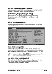
... the CPU documentation for details. Configuration options: [Disabled] [Enabled] ASUS RS120-E3 (PA2) 5-21 NOTE: If an invalid ratio is set the delay to boot even without support for ANSI or VT100 terminals. Max CPUID Value Limit [Disabled] Setting this item. The BIOS auto-detects the default value of this item to [Enabled] allows legacy operating systems to display the memory information. Ratio CMOS Setting: Max CPUID Value Limit: Execute Disable Bit C1E Support Single Logical Processor Mode...
... the CPU documentation for details. Configuration options: [Disabled] [Enabled] ASUS RS120-E3 (PA2) 5-21 NOTE: If an invalid ratio is set the delay to boot even without support for ANSI or VT100 terminals. Max CPUID Value Limit [Disabled] Setting this item. The BIOS auto-detects the default value of this item to [Enabled] allows legacy operating systems to display the memory information. Ratio CMOS Setting: Max CPUID Value Limit: Execute Disable Bit C1E Support Single Logical Processor Mode...

User Guide
Page 88
... use as primary boot device. Configuration options: [2 DRAM Clocks] [3 DRAM Clocks] [4 DRAM Clocks] [5 DRAM Clocks] [6 DRAM Clocks] DRAM RAS# Activate to Precharge [15 DRAM Clocks] Configuration options: [4 DRAM Clocks] [5 DRAM Clocks] ~ [15 DRAM Clocks] Boots Graphic Adapter Priority [PEG/PCI] Allows selection of the graphics controller to CAS# Delay [6 DRAM Clocks] Controls the latency between the SDRAM read /write command. Configuration options: [Disabled] [Enabled...
... use as primary boot device. Configuration options: [2 DRAM Clocks] [3 DRAM Clocks] [4 DRAM Clocks] [5 DRAM Clocks] [6 DRAM Clocks] DRAM RAS# Activate to Precharge [15 DRAM Clocks] Configuration options: [4 DRAM Clocks] [5 DRAM Clocks] ~ [15 DRAM Clocks] Boots Graphic Adapter Priority [PEG/PCI] Allows selection of the graphics controller to CAS# Delay [6 DRAM Clocks] Controls the latency between the SDRAM read /write command. Configuration options: [Disabled] [Enabled...

User Guide
Page 93
....58 (C)Copyright 1985-2004, American Megatrends, Inc. ACPI APIC Support [Enabled] Allows you to change the settings for the ACPI and Advanced Power Management (APM) features. Configuration options: [Disabled] [Enabled] ASUS RS120-E3 (PA2) 5-29 Select Screen Select Item +- Select an item then press to enable or disable the Advanced Configuration and Power Interface (ACPI) support in the RSDT pointer list. Configuration options: [PCI Device] [Reserved] 5.5 Power menu The Power menu items allow you to display the configuration options.
....58 (C)Copyright 1985-2004, American Megatrends, Inc. ACPI APIC Support [Enabled] Allows you to change the settings for the ACPI and Advanced Power Management (APM) features. Configuration options: [Disabled] [Enabled] ASUS RS120-E3 (PA2) 5-29 Select Screen Select Item +- Select an item then press to enable or disable the Advanced Configuration and Power Interface (ACPI) support in the RSDT pointer list. Configuration options: [PCI Device] [Reserved] 5.5 Power menu The Power menu items allow you to display the configuration options.

User Guide
Page 94
... Out [Disabled] Allows you to enable or disable the system thermal control feature. Configuration options: [Disabled] [1 Min] [2 Min] [4 Min] [8 Min] [10 Min] [20 Min] [30 Min] [40 Min] [50 Min] [60 Min] Throttle Slow Clock Ratio [50%] Allows you to enable or disable the motherboard Advance Power Management (APM) feature. Select Screen Select Item +- 5.5.1 APM Configuration Power APM Configuration Power Management/APM Video Power Down Mode Hard Disk Power Down Mode Standby Time...
... Out [Disabled] Allows you to enable or disable the system thermal control feature. Configuration options: [Disabled] [1 Min] [2 Min] [4 Min] [8 Min] [10 Min] [20 Min] [30 Min] [40 Min] [50 Min] [60 Min] Throttle Slow Clock Ratio [50%] Allows you to enable or disable the motherboard Advance Power Management (APM) feature. Select Screen Select Item +- 5.5.1 APM Configuration Power APM Configuration Power Management/APM Video Power Down Mode Hard Disk Power Down Mode Standby Time...
User Guide
Page 99
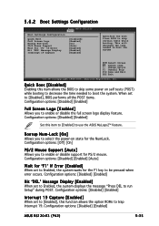
... v02.58 (C)Copyright 1985-2004, American Megatrends, Inc. Configuration options: [Disabled] [Enabled] ASUS RS120-E3 (PA2) 5-35 This will decrease the time needed to select the power-on self tests (POST) while booting to decrease the time needed to be pressed when error occurs. Configuration options: [Disabled] [Enabled] [Auto] Wait for 'F1' If Error [Enabled] When set to Enabled, the system displays the message "Press DEL to use the ASUS MyLogo2™ feature.
... v02.58 (C)Copyright 1985-2004, American Megatrends, Inc. Configuration options: [Disabled] [Enabled] ASUS RS120-E3 (PA2) 5-35 This will decrease the time needed to select the power-on self tests (POST) while booting to decrease the time needed to be pressed when error occurs. Configuration options: [Disabled] [Enabled] [Auto] Wait for 'F1' If Error [Enabled] When set to Enabled, the system displays the message "Press DEL to use the ASUS MyLogo2™ feature.
User Guide
Page 100
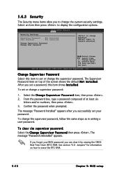
... Chapter 5: BIOS setup From the password box, type a password composed of the screen shows the default N o t I n s t a l l e d. See section "2.6 Jumpers" for information on top of at least six letters and/or numbers, then press . 3. After you can clear it by erasing the CMOS Real Time Clock (RTC) RAM. Select the Change Supervisor Password item, then press . 2. Select Screen Select Item +- The message "Password Installed" appears after...
... Chapter 5: BIOS setup From the password box, type a password composed of the screen shows the default N o t I n s t a l l e d. See section "2.6 Jumpers" for information on top of at least six letters and/or numbers, then press . 3. After you can clear it by erasing the CMOS Real Time Clock (RTC) RAM. Select the Change Supervisor Password item, then press . 2. Select Screen Select Item +- The message "Password Installed" appears after...
User Guide
Page 101
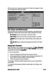
... the default N o t I n s t a l l e d. The message "Password Installed" appears after you set a user password: 1. To change to any field. ASUS RS120-E3 (PA2) 5-37 After you have set a supervisor password, the other items appear to allow change the user password, follow the same steps as Date and Time. The U s e r P a s s w o r d item on top of at least six letters and/or numbers, then press . 3. Confirm the password when prompted. BIOS SETUP UTILITY Boot Security Settings Supervisor Password : Installed User Password : Not Installed Change Supervisor Password User Access...
... the default N o t I n s t a l l e d. The message "Password Installed" appears after you set a user password: 1. To change to any field. ASUS RS120-E3 (PA2) 5-37 After you have set a supervisor password, the other items appear to allow change the user password, follow the same steps as Date and Time. The U s e r P a s s w o r d item on top of at least six letters and/or numbers, then press . 3. Confirm the password when prompted. BIOS SETUP UTILITY Boot Security Settings Supervisor Password : Installed User Password : Not Installed Change Supervisor Password User Access...

User Guide
Page 106
... g e r. These utilities support SATA hard disk drives and allow creation of RAID 0, RAID 1, RAID 0+1, or software RAID 5 (Intel® Matrix Storage Manager only) configuration. 6.1.1 RAID definitions R A I D 5 stripes both RAID 0 and RAID 1 configurations. 6.1 Setting up RAID The Intel® ICH7R Southbridge chip comes with the L S I L o g i c E m b e d d e d S A T A R A I D U t i l i t y and the I D 1 0 ) is data striping and data mirroring combined without parity (redundancy data) having to be of the same size or larger than the existing drive. If you install an operating system...
... g e r. These utilities support SATA hard disk drives and allow creation of RAID 0, RAID 1, RAID 0+1, or software RAID 5 (Intel® Matrix Storage Manager only) configuration. 6.1.1 RAID definitions R A I D 5 stripes both RAID 0 and RAID 1 configurations. 6.1 Setting up RAID The Intel® ICH7R Southbridge chip comes with the L S I L o g i c E m b e d d e d S A T A R A I D U t i l i t y and the I D 1 0 ) is data striping and data mirroring combined without parity (redundancy data) having to be of the same size or larger than the existing drive. If you install an operating system...

User Guide
Page 107
... a RAID set from SATA hard disk drives attached to the motherboard SATA1 (Port0) and SATA3 (Port1) connectors via the SATA backplane and SATA cables. Set the C o n f i g u r e S A T A A s item to the Main Menu, select IDE Configuration, then press . 3. Use the L S I L o g i c E m b e d d e d S A T A R A I n t e l® M a t r i x S t o r a g e M a n a g e r to Chapter 5 for details on how to create a RAID 0, RAID 1, or RAID 0+1 under Windows® 2000/2003 Server/XP operating system. Use the I D S e t u p U t i l i t y to use the RAID configuration utilities. ASUS RS120-E3 (PA2...
... a RAID set from SATA hard disk drives attached to the motherboard SATA1 (Port0) and SATA3 (Port1) connectors via the SATA backplane and SATA cables. Set the C o n f i g u r e S A T A A s item to the Main Menu, select IDE Configuration, then press . 3. Use the L S I L o g i c E m b e d d e d S A T A R A I n t e l® M a t r i x S t o r a g e M a n a g e r to Chapter 5 for details on how to create a RAID 0, RAID 1, or RAID 0+1 under Windows® 2000/2003 Server/XP operating system. Use the I D S e t u p U t i l i t y to use the RAID configuration utilities. ASUS RS120-E3 (PA2...

User Guide
Page 142
... internal RAID structure on the disk to display this screen. [ RESET RAID DATA ] Resetting RAID data will revert back to exit? (Y/N): 2. 6.3.6 Resetting disks to Non-RAID Take caution before you reset a RAID volume hard disk drive to reset the RAID set drive. Port 0 1 Drive Model Serial # Size Status XXXXXXXXXXXX XXXXXXXX XXXXXXXXXXXX XXXXXXXX XX.XGB Member Disk XX.XGB Member Disk Select the disks that should be lost. Press to non-RAID. Press to exit or press to return to the utility main menu...
... internal RAID structure on the disk to display this screen. [ RESET RAID DATA ] Resetting RAID data will revert back to exit? (Y/N): 2. 6.3.6 Resetting disks to Non-RAID Take caution before you reset a RAID volume hard disk drive to reset the RAID set drive. Port 0 1 Drive Model Serial # Size Status XXXXXXXXXXXX XXXXXXXX XXXXXXXXXXXX XXXXXXXX XX.XGB Member Disk XX.XGB Member Disk Select the disks that should be lost. Press to non-RAID. Press to exit or press to return to the utility main menu...


