

User Guide
Page 3
... setup 2.1 Chassis cover 2-2 2.1.1 Removing the cover 2-2 2.1.2 Installing the cover 2-3 2.2 Central Processing Unit (CPU 2-4 2.2.1 Installing the CPU 2-4 2.2.2 Installing the CPU heatsink and airduct 2-6 2.3 System memory 2-8 2.3.1 DIMM sockets location 2-8 2.3.2 Memory configurations 2-8 2.3.3 Installing a DIMM 2-9 2.3.4 Removing a DIMM 2-9 2.4 Hard disk drives 2-10 2.5 Expansion slot 2-12 2.5.1 Installing an expansion card to the riser card bracket 2-12 2.5.2 Reinstalling the...
... setup 2.1 Chassis cover 2-2 2.1.1 Removing the cover 2-2 2.1.2 Installing the cover 2-3 2.2 Central Processing Unit (CPU 2-4 2.2.1 Installing the CPU 2-4 2.2.2 Installing the CPU heatsink and airduct 2-6 2.3 System memory 2-8 2.3.1 DIMM sockets location 2-8 2.3.2 Memory configurations 2-8 2.3.3 Installing a DIMM 2-9 2.3.4 Removing a DIMM 2-9 2.4 Hard disk drives 2-10 2.5 Expansion slot 2-12 2.5.1 Installing an expansion card to the riser card bracket 2-12 2.5.2 Reinstalling the...

User Guide
Page 13
...x 445 mm (w) x 43.6 mm (h) ASUS RS120-E3 (PA2) 1-3 1.2 System specifications The ASUS RS120-E3 (PA2) is a 1U barebone server system featuring the ASUS P5MT-R motherboard. The server supports the Intel&#...174; Pentium® 4 and Pentium® D processor in the LGA775 package, and includes the latest technologies through the chipsets embedded on the motherboard. Chassis Rackmount 1U (R10) Motherboard ASUS P5MT-R Chipset North Bridge : Intel® E7230 Memory...
...x 445 mm (w) x 43.6 mm (h) ASUS RS120-E3 (PA2) 1-3 1.2 System specifications The ASUS RS120-E3 (PA2) is a 1U barebone server system featuring the ASUS P5MT-R motherboard. The server supports the Intel&#...174; Pentium® 4 and Pentium® D processor in the LGA775 package, and includes the latest technologies through the chipsets embedded on the motherboard. Chassis Rackmount 1U (R10) Motherboard ASUS P5MT-R Chipset North Bridge : Intel® E7230 Memory...

User Guide
Page 22
... (cross) screwdriver just enough to attach the heatsink to the Appendix for more information on top of the four screws with the Intel® Enhanced Memory 64 Technology (EM64T), Enhanced Intel SpeedStep® Technology (EIST), and Hyper-Threading Technology. When the four screws are attached, tighten them one by one correct...
... (cross) screwdriver just enough to attach the heatsink to the Appendix for more information on top of the four screws with the Intel® Enhanced Memory 64 Technology (EM64T), Enhanced Intel SpeedStep® Technology (EIST), and Hyper-Threading Technology. When the four screws are attached, tighten them one by one correct...

User Guide
Page 24
...: ® P5MT-R 128 Pins 112 Pins DIMM_A2 DIMM_A1 DIMM_B2 DIMM_B1 P5MT-R 240-pin DDR2 DIMM sockets 2.3.2 Memory configurations You may detect less than 4 GB when you installed four 2 GB DDR2 memory modules - populated (2) - Visit the ASUS website for an updated DDR2 Qualified Vendors List for this motherboard. • Due to the DIMM sockets...
...: ® P5MT-R 128 Pins 112 Pins DIMM_A2 DIMM_A1 DIMM_B2 DIMM_B1 P5MT-R 240-pin DDR2 DIMM sockets 2.3.2 Memory configurations You may detect less than 4 GB when you installed four 2 GB DDR2 memory modules - populated (2) - Visit the ASUS website for an updated DDR2 Qualified Vendors List for this motherboard. • Due to the DIMM sockets...

User Guide
Page 36
.... 4. Uninstall the fan following the instructions in the previous section. 3 1 2 Peg 2-20 Chapter 2: Hardware setup 2.8.2 System fan with dummy case The system fan for the memory module(s) comes with a dummy case that allows it fits in place. 4. To reinstall the system fan with dummy case: 1. To replace the system fan with...
.... 4. Uninstall the fan following the instructions in the previous section. 3 1 2 Peg 2-20 Chapter 2: Hardware setup 2.8.2 System fan with dummy case The system fan for the memory module(s) comes with a dummy case that allows it fits in place. 4. To reinstall the system fan with dummy case: 1. To replace the system fan with...
User Guide
Page 50
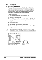
... the RTC RAM, never remove the cap on pins 2-3 for about 5~10 seconds, then move the cap back to pins 2-3. You can clear the CMOS memory of date, time, and system setup parameters by erasing the CMOS RTC RAM data. Hold down the key during the boot process and enter BIOS...
... the RTC RAM, never remove the cap on pins 2-3 for about 5~10 seconds, then move the cap back to pins 2-3. You can clear the CMOS memory of date, time, and system setup parameters by erasing the CMOS RTC RAM data. Hold down the key during the boot process and enter BIOS...

User Guide
Page 82
.... Main AMIBIOS Version : 08.00.11 Build Date : 06/14/05 BIOS SETUP UTILITY Processor Type Speed Count : Genuine Intel(R) CPU 3.00GHz : 3000 MHz : 1 System Memory Total : 1024MB Select Screen Select Item +- Processor Displays the auto-detected CPU specification. The BIOS automatically detects the items in this menu. Change Option F1... General Help F10 Save and Exit ESC Exit v02.58 (C)Copyright 1985-2004, American Megatrends, Inc. PIO Mode [Auto] Selects the PIO mode. System Memory Displays the auto-detected total system memory. 5-18 Chapter 5: BIOS setup
.... Main AMIBIOS Version : 08.00.11 Build Date : 06/14/05 BIOS SETUP UTILITY Processor Type Speed Count : Genuine Intel(R) CPU 3.00GHz : 3000 MHz : 1 System Memory Total : 1024MB Select Screen Select Item +- Processor Displays the auto-detected CPU specification. The BIOS automatically detects the items in this menu. Change Option F1... General Help F10 Save and Exit ESC Exit v02.58 (C)Copyright 1985-2004, American Megatrends, Inc. PIO Mode [Auto] Selects the PIO mode. System Memory Displays the auto-detected total system memory. 5-18 Chapter 5: BIOS setup
User Guide
Page 84
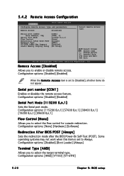
... Access [Disabled] Serial port number Base Address, IRQ Serial Port Mode Flow Control Redirection After BIOS POST Terminal Type VT-UTFB Combo Key Support Sredir Memory Display Delay [COM1] [3F8h, 4] [115200 8,n,1] [None] [Always] [ANSI] [Enabled] [No Delay] Select Remote Access type.
... Access [Disabled] Serial port number Base Address, IRQ Serial Port Mode Flow Control Redirection After BIOS POST Terminal Type VT-UTFB Combo Key Support Sredir Memory Display Delay [COM1] [3F8h, 4] [115200 8,n,1] [None] [Always] [ANSI] [Enabled] [No Delay] Select Remote Access type.
User Guide
Page 85
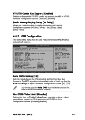
...[ 8]...[28] You can only adjust the R a t i o C M O S if you to set in this item. Configuration options: [Disabled] [Enabled] ASUS RS120-E3 (PA2) 5-21 Configuration options: [No Delay] [Delay 1 Sec] [Delay 2 Sec] [Delay 4 Sec] 4.4.3 CPU Configuration The items in CMOS then actual and setpoint ... [ 15] [Disabled] [Enabled] [Disabled] [Disabled] [Automatic] Select Screen Select Item +- Configuration options: [Disabled] [Enabled] Sredir Memory Display Delay [No Delay] Allows you installed an unlocked CPU. VT-UTF8 Combo Key Support [Enabled] Enables or disables the VT-UTF8 combo...
...[ 8]...[28] You can only adjust the R a t i o C M O S if you to set in this item. Configuration options: [Disabled] [Enabled] ASUS RS120-E3 (PA2) 5-21 Configuration options: [No Delay] [Delay 1 Sec] [Delay 2 Sec] [Delay 4 Sec] 4.4.3 CPU Configuration The items in CMOS then actual and setpoint ... [ 15] [Disabled] [Enabled] [Disabled] [Disabled] [Automatic] Select Screen Select Item +- Configuration options: [Disabled] [Enabled] Sredir Memory Display Delay [No Delay] Allows you installed an unlocked CPU. VT-UTF8 Combo Key Support [Enabled] Enables or disables the VT-UTF8 combo...
User Guide
Page 87
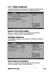
...v02.58 (C)Copyright 1985-2004, American Megatrends, Inc. DISABLE: Do not allow remapping of overlapped PCI memory above the total physical memory. Select an item then press to change the advanced chipset settings. Onboard LAN Boot ROM [Enabled] ...[Enabled] Boots Graphic Adapter Priority [PEG/PCI] PEG Port Configuration PEG Port [Auto] ENABLE: Allow remapping of memory. Configuration options: [Disabled] [Enabled] ASUS RS120-E3 (PA2) 5-23 North Bridge Configuration South Bridge Configuration Intel PCI-X Hub Configuration Onboard LAN Boot ROM [Enabled] Configure North ...
...v02.58 (C)Copyright 1985-2004, American Megatrends, Inc. DISABLE: Do not allow remapping of overlapped PCI memory above the total physical memory. Select an item then press to change the advanced chipset settings. Onboard LAN Boot ROM [Enabled] ...[Enabled] Boots Graphic Adapter Priority [PEG/PCI] PEG Port Configuration PEG Port [Auto] ENABLE: Allow remapping of memory. Configuration options: [Disabled] [Enabled] ASUS RS120-E3 (PA2) 5-23 North Bridge Configuration South Bridge Configuration Intel PCI-X Hub Configuration Onboard LAN Boot ROM [Enabled] Configure North ...

User Guide
Page 92
...-2004, American Megatrends, Inc. The menu includes setting the IRQ and DMA channel resources for either PCI/PnP or legacy ISA devices, and setting the memory size block for boot if your system has a Plug ans Play operating system.
...-2004, American Megatrends, Inc. The menu includes setting the IRQ and DMA channel resources for either PCI/PnP or legacy ISA devices, and setting the memory size block for boot if your system has a Plug ans Play operating system.