
User Guide
Page 4
... the rails to the rack 3-3 3.4 Rackmounting the server 3-4 Chapter 4: Motherboard information 4.1 Motherboard layout 4-2 4.2 Jumpers 4-4 4.3 Connectors 4-9 Chapter 5: BIOS setup 5.1 Managing and updating your BIOS 5-2 5.1.1 Creating a bootable floppy disk 5-2 5.1.2 AFUDOS utility 5-3 5.1.3 ASUS CrashFree BIOS 2 utility 5-6 5.1.4 ASUS Update utility 5-8 5.2 BIOS setup program 5-11 5.2.1 BIOS menu screen 5-12 5.2.2 Menu bar 5-12 5.2.3 Navigation keys 5-12 5.2.4 Menu items 5-13 5.2.5 Sub-menu items 5-13...
... the rails to the rack 3-3 3.4 Rackmounting the server 3-4 Chapter 4: Motherboard information 4.1 Motherboard layout 4-2 4.2 Jumpers 4-4 4.3 Connectors 4-9 Chapter 5: BIOS setup 5.1 Managing and updating your BIOS 5-2 5.1.1 Creating a bootable floppy disk 5-2 5.1.2 AFUDOS utility 5-3 5.1.3 ASUS CrashFree BIOS 2 utility 5-6 5.1.4 ASUS Update utility 5-8 5.2 BIOS setup program 5-11 5.2.1 BIOS menu screen 5-12 5.2.2 Menu bar 5-12 5.2.3 Navigation keys 5-12 5.2.4 Menu items 5-13 5.2.5 Sub-menu items 5-13...

User Guide
Page 5
... Settings Configuration 5-35 5.6.3 Security 5-36 5.7 Exit menu 5-39 Chapter 6: RAID configuration 6.1 Setting up RAID 6-2 6.1.1 RAID definitions 6-2 6.1.2 Installing hard disk drives 6-3 6.1.3 Setting the RAID item in BIOS 6-3 6.1.4 RAID configuration utility 6-3 6.2 LSI Logic Embedded SATA RAID Setup Utility 6-4 6.2.1 Creating a RAID 0 or RAID 1 set 6-5 6.2.2 Creating a RAID 10 set 6-11 6.2.3 Adding or viewing a RAID configuration...
... Settings Configuration 5-35 5.6.3 Security 5-36 5.7 Exit menu 5-39 Chapter 6: RAID configuration 6.1 Setting up RAID 6-2 6.1.1 RAID definitions 6-2 6.1.2 Installing hard disk drives 6-3 6.1.3 Setting the RAID item in BIOS 6-3 6.1.4 RAID configuration utility 6-3 6.2 LSI Logic Embedded SATA RAID Setup Utility 6-4 6.2.1 Creating a RAID 0 or RAID 1 set 6-5 6.2.2 Creating a RAID 10 set 6-11 6.2.3 Adding or viewing a RAID configuration...
User Guide
Page 9
...contains the following parts: 1. Chapter 6: RAID configuration This chapter tells how to change system settings through the BIOS Setup menus and describes the BIOS parameters. 6. About this guide Audience This user guide is intended for different system components. 8. Chapter 3: ... how to when configuring the motherboard. Chapter 5: BIOS information This chapter tells how to change system settings through the BIOS Setup menus. Chapter 1: Product Introduction This chapter describes the general features of the BIOS parameters are also provided. 7 Chapter 7: Driver installation...
...contains the following parts: 1. Chapter 6: RAID configuration This chapter tells how to change system settings through the BIOS Setup menus and describes the BIOS parameters. 6. About this guide Audience This user guide is intended for different system components. 8. Chapter 3: ... how to when configuring the motherboard. Chapter 5: BIOS information This chapter tells how to change system settings through the BIOS Setup menus. Chapter 1: Product Introduction This chapter describes the general features of the BIOS parameters are also provided. 7 Chapter 7: Driver installation...
User Guide
Page 31
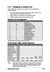
Assign an IRQ to the following tables. 3. ASUS RS120-E3 (PA2) 2-15 2.5.3 Configuring an expansion card After installing the expansion card,...PXIRQ1 PXIRQ2 PXIRQ3 REQ1# PXREQ0 PIRQF# PIRQG# PIRQH# REQ0# GNT# GNT1# PXGNT0 GNT0# When using PCI cards on BIOS setup. 2. See Chapter 5 for information on shared slots, ensure that the drivers support "Share IRQ" or that the...*These IRQs are usually available for the expansion card. Turn on the system and change the necessary BIOS settings, if any. Install the software drivers for ISA or PCI devices. Otherwise, conflicts will arise...
Assign an IRQ to the following tables. 3. ASUS RS120-E3 (PA2) 2-15 2.5.3 Configuring an expansion card After installing the expansion card,...PXIRQ1 PXIRQ2 PXIRQ3 REQ1# PXREQ0 PIRQF# PIRQG# PIRQH# REQ0# GNT# GNT1# PXGNT0 GNT0# When using PCI cards on BIOS setup. 2. See Chapter 5 for information on shared slots, ensure that the drivers support "Share IRQ" or that the...*These IRQs are usually available for the expansion card. Turn on the system and change the necessary BIOS settings, if any. Install the software drivers for ISA or PCI devices. Otherwise, conflicts will arise...

User Guide
Page 48
...,240-pin module) DDR2 DIMM_B1 (64 bit,240-pin module) Intel® E7230 CR2032 3V Lithium Cell CMOS Power Intel® 6702 PXH-V 8Mbit Flash BIOS RECOVERY1 COM2 REAR_FAN1 BMCSOCKET1 LPT1 I/O Super PCIE2 ATXPWR1 ATX12V1 LGA775 BPSMB1 CLRTC1 Intel® ICH7R RAID_SEL1 USB34 PANEL1 USBPW34 SATA1 SATA2 SATA3 SATA4 FRNT_FAN1 FRNT_FAN2...
...,240-pin module) DDR2 DIMM_B1 (64 bit,240-pin module) Intel® E7230 CR2032 3V Lithium Cell CMOS Power Intel® 6702 PXH-V 8Mbit Flash BIOS RECOVERY1 COM2 REAR_FAN1 BMCSOCKET1 LPT1 I/O Super PCIE2 ATXPWR1 ATX12V1 LGA775 BPSMB1 CLRTC1 Intel® ICH7R RAID_SEL1 USB34 PANEL1 USBPW34 SATA1 SATA2 SATA3 SATA4 FRNT_FAN1 FRNT_FAN2...

User Guide
Page 49
... button/soft-off button (Yellow 2-pin PWRSW) Reset button (Blue 2-pin RESET) Page 4-9 4-9 4-10 4-11 4-11 4-12 4-12 4-13 4-14 4-14 4-15 4-15 4-16 4-17 ASUS RS120-E3 (PA2) 4-3 Force BIOS recovery (3-pin RECOVERY1) Page 4-4 4-5 4-5 4-6 4-6 4-7 4-7 4-8 Internal connectors 1. Auxiliary panel connector (20-pin AUX_PANEL1) Front panel SMB (6-1 pin FPSMB) LAN activity LED (2-pin LAN1_LED, LAN2_LED) Chassis...
... button/soft-off button (Yellow 2-pin PWRSW) Reset button (Blue 2-pin RESET) Page 4-9 4-9 4-10 4-11 4-11 4-12 4-12 4-13 4-14 4-14 4-15 4-15 4-16 4-17 ASUS RS120-E3 (PA2) 4-3 Force BIOS recovery (3-pin RECOVERY1) Page 4-4 4-5 4-5 4-6 4-6 4-7 4-7 4-8 Internal connectors 1. Auxiliary panel connector (20-pin AUX_PANEL1) Front panel SMB (6-1 pin FPSMB) LAN activity LED (2-pin LAN1_LED, LAN2_LED) Chassis...
User Guide
Page 50
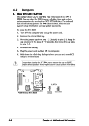
... pins 1-2 (default) to re-enter data. Plug the power cord and turn ON the computer. 6. Hold down the key during the boot process and enter BIOS setup to pins 2-3. You can clear the CMOS memory of date, time, and system setup parameters by erasing the CMOS RTC RAM data. Removing the...
... pins 1-2 (default) to re-enter data. Plug the power cord and turn ON the computer. 6. Hold down the key during the boot process and enter BIOS setup to pins 2-3. You can clear the CMOS memory of date, time, and system setup parameters by erasing the CMOS RTC RAM data. Removing the...
User Guide
Page 51
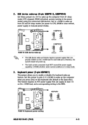
... to enable or disable the keyboard wake-up from S1 sleep mode (CPU stopped, DRAM refreshed, system running in the BIOS. ® P5MT-R KBPWR1 1 2 +5V (Default) 2 3 +5VSB P5MT-R Keyboard power setting ASUS RS120-E3 (PA2) 4-5 This feature requires an ATX power supply that can supply at least 1A on the +5VSB lead for each USB...
... to enable or disable the keyboard wake-up from S1 sleep mode (CPU stopped, DRAM refreshed, system running in the BIOS. ® P5MT-R KBPWR1 1 2 +5V (Default) 2 3 +5VSB P5MT-R Keyboard power setting ASUS RS120-E3 (PA2) 4-5 This feature requires an ATX power supply that can supply at least 1A on the +5VSB lead for each USB...

User Guide
Page 54
...back to pins 2-3. 3. 8 . To update the BIOS: 1. Set the jumper to pins 1-2. 6. Restart the system, then insert the CD-ROM to the optical drive to update/recover the BIOS quickly. Prepare a CD-ROM that contains the original or latest BIOS for the motherboard (P5MTR.ROM) and the AFUDOS.EXE ...utility. 2. Force BIOS recovery (3-pin RECOVERY1) This jumper allows you to update or recover the...
...back to pins 2-3. 3. 8 . To update the BIOS: 1. Set the jumper to pins 1-2. 6. Restart the system, then insert the CD-ROM to the optical drive to update/recover the BIOS quickly. Prepare a CD-ROM that contains the original or latest BIOS for the motherboard (P5MTR.ROM) and the AFUDOS.EXE ...utility. 2. Force BIOS recovery (3-pin RECOVERY1) This jumper allows you to update or recover the...

User Guide
Page 56
Serial ATA connectors (7-pin SATA1, SATA2, SATA3, SATA4) These connectors are set the Configure SATA As item in the BIOS to I D E mode by default. If you intend to create a Serial ATA RAID set using the LSI Logic Embedded SATA RAID utility in I D E mode, you can ...
Serial ATA connectors (7-pin SATA1, SATA2, SATA3, SATA4) These connectors are set the Configure SATA As item in the BIOS to I D E mode by default. If you intend to create a Serial ATA RAID set using the LSI Logic Embedded SATA RAID utility in I D E mode, you can ...

User Guide
Page 64
• ATX power button/soft-off mode depending on or puts the system in sleep or soft-off button (Yellow 2-pin PWRSW) This connector is for the chassis-mounted reset button for the system power button. Pressing the power button turns the system on the BIOS settings. Pressing the power switch for more than four seconds while the system is ON turns the system OFF. • Reset button (Blue 2-pin RESET) This 2-pin connector is for system reboot without turning off the system power. 4-18 Chapter 4: Motherboard information
• ATX power button/soft-off mode depending on or puts the system in sleep or soft-off button (Yellow 2-pin PWRSW) This connector is for the chassis-mounted reset button for the system power button. Pressing the power button turns the system on the BIOS settings. Pressing the power switch for more than four seconds while the system is ON turns the system OFF. • Reset button (Blue 2-pin RESET) This 2-pin connector is for system reboot without turning off the system power. 4-18 Chapter 4: Motherboard information

User Guide
Page 65
BIOS setup Chapter 5 This chapter tells how to change the system settings through the BIOS Setup menus. Detailed descriptions of the BIOS parameters are also provided. ASUS RS120-E3 (PA2)
BIOS setup Chapter 5 This chapter tells how to change the system settings through the BIOS Setup menus. Detailed descriptions of the BIOS parameters are also provided. ASUS RS120-E3 (PA2)

User Guide
Page 66
... Windows® environment.) Refer to the bootable floppy disk. 5-2 Chapter 5: BIOS setup Copy the original motherboard BIOS using a bootable floppy disk or the motherboard support CD when the BIOS file fails or gets corrupted.) 3. DOS environment a. c. A S U S C r a s h F r e e B I O S 2 (Updates the BIOS using the ASUS Update or AFUDOS utilities. 5.1.1 Creating a bootable floppy disk 1. Do either one of the...
... Windows® environment.) Refer to the bootable floppy disk. 5-2 Chapter 5: BIOS setup Copy the original motherboard BIOS using a bootable floppy disk or the motherboard support CD when the BIOS file fails or gets corrupted.) 3. DOS environment a. c. A S U S C r a s h F r e e B I O S 2 (Updates the BIOS using the ASUS Update or AFUDOS utilities. 5.1.1 Creating a bootable floppy disk 1. Do either one of the...

User Guide
Page 67
...motherboard support CD to file...... Press . ASUS RS120-E3 (PA2) 5-3 The actual BIOS screen displays may not be the same as backup when the BIOS fails or gets corrupted during the updating process. A:\>afudos /oOLDBIOS1.rom AMI Firmware Update Utility - Version 1.19(ASUS V2.07(03.11.24BB)) Copyright (C)... 2002 American Megatrends, Inc. Reading flash ..... done Write to the bootable floppy disk you to save the file. • The succeeding BIOS screens are for the extension name. This utility...
...motherboard support CD to file...... Press . ASUS RS120-E3 (PA2) 5-3 The actual BIOS screen displays may not be the same as backup when the BIOS fails or gets corrupted during the updating process. A:\>afudos /oOLDBIOS1.rom AMI Firmware Update Utility - Version 1.19(ASUS V2.07(03.11.24BB)) Copyright (C)... 2002 American Megatrends, Inc. Reading flash ..... done Write to the bootable floppy disk you to save the file. • The succeeding BIOS screens are for the extension name. This utility...

User Guide
Page 68
... disk you created earlier. 3. A:\>afudos /iP5MTR.ROM AMI Firmware Update Utility - Visit the ASUS website (www.asus.com) and download the latest BIOS file for the motherboard. All rights reserved. done Reading flash ...... Updating the BIOS file To update the BIOS file using the AFUDOS utility: 1. A:\>afudos /iP5MTR.rom The utility verifies the file, then...
... disk you created earlier. 3. A:\>afudos /iP5MTR.ROM AMI Firmware Update Utility - Visit the ASUS website (www.asus.com) and download the latest BIOS file for the motherboard. All rights reserved. done Reading flash ...... Updating the BIOS file To update the BIOS file using the AFUDOS utility: 1. A:\>afudos /iP5MTR.rom The utility verifies the file, then...

User Guide
Page 69
...T 1 6, then click the S t a r t button. Version 1.19(ASUS V2.07(03.11.24BB)) Copyright (C) 2002 American Megatrends, Inc. done Verifying flash .... Boot the system from the menu. 4. done Please restart your computer A:\> Updating the BIOS file using a USB flash drive If you have not purchased a USB floppy disk... in the previous section to FAT16 or 32 system file before updating the BIOS. Do not turn off power during flash BIOS Reading file ....... done Reading flash ...... ASUS RS120-E3 (PA2) 5-5 done Advance Check ...... done Writing flash ...... Right-click the USB...
...T 1 6, then click the S t a r t button. Version 1.19(ASUS V2.07(03.11.24BB)) Copyright (C) 2002 American Megatrends, Inc. done Verifying flash .... Boot the system from the menu. 4. done Please restart your computer A:\> Updating the BIOS file using a USB flash drive If you have not purchased a USB floppy disk... in the previous section to FAT16 or 32 system file before updating the BIOS. Do not turn off power during flash BIOS Reading file ....... done Reading flash ...... ASUS RS120-E3 (PA2) 5-5 done Advance Check ...... done Writing flash ...... Right-click the USB...

User Guide
Page 70
... of your motherboard, e.g. Floppy found , the utility reads the BIOS file and starts flashing the corrupted BIOS file. Restart the system after the utility completes the updating process. 5-6 Chapter 5: BIOS setup You can cause system boot failure! 4. Checking for floppy... 5.1.3 ASUS CrashFree BIOS 2 utility The ASUS CrashFree BIOS 2 is an auto recovery tool that you to the...
... of your motherboard, e.g. Floppy found , the utility reads the BIOS file and starts flashing the corrupted BIOS file. Restart the system after the utility completes the updating process. 5-6 Chapter 5: BIOS setup You can cause system boot failure! 4. Checking for floppy... 5.1.3 ASUS CrashFree BIOS 2 utility The ASUS CrashFree BIOS 2 is an auto recovery tool that you to the...

User Guide
Page 71
... the optical drive. 3. Remove any floppy disk from the support CD: 1. Starting BIOS recovery... Checking for the original or updated BIOS file. Floppy not found ! Checking for this motherboard. ASUS RS120-E3 (PA2) 5-7 Start flashing... Recovering the BIOS from the support CD To recover the BIOS from the floppy disk drive, then turn on the system. 2. The recovered...
... the optical drive. 3. Remove any floppy disk from the support CD: 1. Starting BIOS recovery... Checking for the original or updated BIOS file. Floppy not found ! Checking for this motherboard. ASUS RS120-E3 (PA2) 5-7 Start flashing... Recovering the BIOS from the support CD To recover the BIOS from the floppy disk drive, then turn on the system. 2. The recovered...
User Guide
Page 72
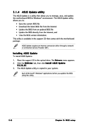
... is copied to : • Save the current BIOS file • Download the latest BIOS file from the Internet • Update the BIOS from an updated BIOS file • Update the BIOS directly from the Internet, and • View the BIOS version information. The D r i v e r s menu appears. 2. 5.1.4 ASUS Update utility The ASUS Update is a utility that comes with the motherboard...
... is copied to : • Save the current BIOS file • Download the latest BIOS file from the Internet • Update the BIOS from an updated BIOS file • Update the BIOS directly from the Internet, and • View the BIOS version information. The D r i v e r s menu appears. 2. 5.1.4 ASUS Update utility The ASUS Update is a utility that comes with the motherboard...

User Guide
Page 73
The ASUS Update main window appears. 2. N e x t. ASUS RS120-E3 (PA2) 5-9 Select the ASUS FTP site t h e I O S f r o m 3. Updating the BIOS through the Internet To update the BIOS through the Internet: 1. Select U p d a t e B I n t e r n e t option from the Windows® desktop by clicking S t a r t > P r o g r a m s > A S U S > A S U S U p d a t e > A S U S U p d a t e. Click N e x t. Launch the ASUS Update utility from the nearest you to avoid network drop-down menu, then click traffic, or click A u t o S e l e c t.
The ASUS Update main window appears. 2. N e x t. ASUS RS120-E3 (PA2) 5-9 Select the ASUS FTP site t h e I O S f r o m 3. Updating the BIOS through the Internet To update the BIOS through the Internet: 1. Select U p d a t e B I n t e r n e t option from the Windows® desktop by clicking S t a r t > P r o g r a m s > A S U S > A S U S U p d a t e > A S U S U p d a t e. Click N e x t. Launch the ASUS Update utility from the nearest you to avoid network drop-down menu, then click traffic, or click A u t o S e l e c t.
