
Users Manual English
Page 3
Contents Safety information...iv About this guide...v ROG STRIX B550-F GAMING specifications summary vi Connectors with shared bandwidth x Package contents...xi Installation tools and components xii Chapter 1: Product Introduction 1.1 Before you proceed 1-1 1.2 Motherboard layout 1-2 Chapter 2: Basic Installation 2.1 Building your PC system 2-1 2.1.1 CPU installation 2-1 2.1.2 Cooling system installation 2-2 2.1.3 DIMM installation 2-5 2.1.4 M.2 installation 2-6 2.1.5 Motherboard installation 2-8 2.1.6 ATX power connection 2-9 2.1.7 SATA device connection 2-9 2.1.8 ...
Contents Safety information...iv About this guide...v ROG STRIX B550-F GAMING specifications summary vi Connectors with shared bandwidth x Package contents...xi Installation tools and components xii Chapter 1: Product Introduction 1.1 Before you proceed 1-1 1.2 Motherboard layout 1-2 Chapter 2: Basic Installation 2.1 Building your PC system 2-1 2.1.1 CPU installation 2-1 2.1.2 Cooling system installation 2-2 2.1.3 DIMM installation 2-5 2.1.4 M.2 installation 2-6 2.1.5 Motherboard installation 2-8 2.1.6 ATX power connection 2-9 2.1.7 SATA device connection 2-9 2.1.8 ...

Users Manual English
Page 4
... with the package. • Before using the product, ensure all cables are correctly connected and the power cables are not damaged. Operation safety • Before installing the motherboard and adding devices on a stable surface. • If you encounter technical problems with ambient temperatures between 0°C and 40°C. Contact a qualified service...
... with the package. • Before using the product, ensure all cables are correctly connected and the power cables are not damaged. Operation safety • Before installing the motherboard and adding devices on a stable surface. • If you encounter technical problems with ambient temperatures between 0°C and 40°C. Contact a qualified service...

Users Manual English
Page 5
... The ASUS website (www.asus.com) provides updated information on RAID. CAUTION: Information to prevent damage to the components and injuries to yourself when trying to help you need when installing and configuring the motherboard. v Where to find more information Refer to the following parts: ... to perform when installing system components. • Chapter 3: BIOS and RAID Support This chapter tells how to complete a task. IMPORTANT: Instructions that you MUST follow to boot into the BIOS, upgrade BIOS using the EZ Flash Utility and support on ASUS hardware and software ...
... The ASUS website (www.asus.com) provides updated information on RAID. CAUTION: Information to prevent damage to the components and injuries to yourself when trying to help you need when installing and configuring the motherboard. v Where to find more information Refer to the following parts: ... to perform when installing system components. • Chapter 3: BIOS and RAID Support This chapter tells how to complete a task. IMPORTANT: Instructions that you MUST follow to boot into the BIOS, upgrade BIOS using the EZ Flash Utility and support on ASUS hardware and software ...
Users Manual English
Page 11
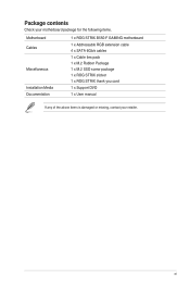
xi Package contents Check your motherboard package for the following items. Motherboard Cables Miscellaneous Installation Media Documentation 1 x ROG STRIX B550-F GAMING motherboard 1 x Addressable RGB extension cable 4 x SATA 6Gb/s cables 1 x Cable ties pack 1 x M.2 Rubber Package 1 x M.2 SSD screw package 1 x ROG STRIX sticker 1 x ROG STRIX thank you card 1 x Support DVD 1 x User manual If any of the above items is damaged or missing, contact your retailer.
xi Package contents Check your motherboard package for the following items. Motherboard Cables Miscellaneous Installation Media Documentation 1 x ROG STRIX B550-F GAMING motherboard 1 x Addressable RGB extension cable 4 x SATA 6Gb/s cables 1 x Cable ties pack 1 x M.2 Rubber Package 1 x M.2 SSD screw package 1 x ROG STRIX sticker 1 x ROG STRIX thank you card 1 x Support DVD 1 x User manual If any of the above items is damaged or missing, contact your retailer.

Users Manual English
Page 12
Installation tools and components PC chassis Phillips (cross) screwdriver Power supply unit AMD AM4 CPU AMD AM4/AM3 compatible CPU Fan DDR4 DIMM SATA hard disk drive SATA optical disc drive (optional) Graphics card (optional) M.2 SSD module (optional) 1 Bag of screws The tools and components in the table above are not included in the motherboard package. xii
Installation tools and components PC chassis Phillips (cross) screwdriver Power supply unit AMD AM4 CPU AMD AM4/AM3 compatible CPU Fan DDR4 DIMM SATA hard disk drive SATA optical disc drive (optional) Graphics card (optional) M.2 SSD module (optional) 1 Bag of screws The tools and components in the table above are not included in the motherboard package. xii
Users Manual English
Page 13
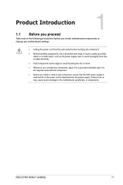
Chapter 1 Chapter 1: Product Introduction Product Introduction 1 1.1 Before you proceed Take note of the following precautions before you install motherboard components or change any motherboard settings. • Unplug the power cord from the wall socket before touching any component. • ...you uninstall any component, place it on a grounded antistatic pad or in the bag that came with the component. • Before you install or remove any component, ensure that the ATX power supply is switched off or the power cord is detached from the power supply. ROG STRIX B550-F GAMING 1-1
Chapter 1 Chapter 1: Product Introduction Product Introduction 1 1.1 Before you proceed Take note of the following precautions before you install motherboard components or change any motherboard settings. • Unplug the power cord from the wall socket before touching any component. • ...you uninstall any component, place it on a grounded antistatic pad or in the bag that came with the component. • Before you install or remove any component, ensure that the ATX power supply is switched off or the power cord is detached from the power supply. ROG STRIX B550-F GAMING 1-1

Users Manual English
Page 16
SOCKET AM4 The AM4 socket has a different pinout design. DO NOT force the CPU into the socket to prevent bending the connectors on the socket and damaging the CPU! CPU socket The motherboard comes with an AMD Socket AM4 designed for the AM4 socket. The CPU fits in only one correct orientation. Ensure that you use a CPU designed for 3rd Gen AMD Ryzen™ Processors. Ensure that all power cables are unplugged before installing the CPU. 1-4 Chapter 1: Product Introduction Chapter 1 1.
SOCKET AM4 The AM4 socket has a different pinout design. DO NOT force the CPU into the socket to prevent bending the connectors on the socket and damaging the CPU! CPU socket The motherboard comes with an AMD Socket AM4 designed for the AM4 socket. The CPU fits in only one correct orientation. Ensure that you use a CPU designed for 3rd Gen AMD Ryzen™ Processors. Ensure that all power cables are unplugged before installing the CPU. 1-4 Chapter 1: Product Introduction Chapter 1 1.

Users Manual English
Page 17
Recommended memory configurations ROG STRIX B550-F GAMING 1-5 A DDR4 memory module is notched differently from a DDR, DDR2, or DDR3 module. DO NOT install a DDR, DDR2, or DDR3 memory module to the DDR4 slot. DIMM_B1 DIMM_B2* DIMM_A1 DIMM_A2* Chapter 1 2. DIMM slots The motherboard comes with Dual Inline Memory Modules (DIMM) slots designed for DDR4 (Double Data Rate 4) memory modules.
Recommended memory configurations ROG STRIX B550-F GAMING 1-5 A DDR4 memory module is notched differently from a DDR, DDR2, or DDR3 module. DO NOT install a DDR, DDR2, or DDR3 memory module to the DDR4 slot. DIMM_B1 DIMM_B2* DIMM_A1 DIMM_A2* Chapter 1 2. DIMM slots The motherboard comes with Dual Inline Memory Modules (DIMM) slots designed for DDR4 (Double Data Rate 4) memory modules.

Users Manual English
Page 18
... for the dual-channel configuration. The system maps the total size of the same version or data code (D/C) from a memory module. You may install 4 GB, 8 GB, 16 GB, and 32 GB unbuffered ECC and non‑ECC DDR4 DIMMs into the DIMM sockets. Under the default state... a more efficient memory cooling system to support a full memory load or overclocking condition. • Always install the DIMMS with the vendor to get the correct memory modules. • Visit the ASUS website for single-channel operation. • The default memory operation frequency is dependent on its Serial Presence ...
... for the dual-channel configuration. The system maps the total size of the same version or data code (D/C) from a memory module. You may install 4 GB, 8 GB, 16 GB, and 32 GB unbuffered ECC and non‑ECC DDR4 DIMMs into the DIMM sockets. Under the default state... a more efficient memory cooling system to support a full memory load or overclocking condition. • Always install the DIMMS with the vendor to get the correct memory modules. • Visit the ASUS website for single-channel operation. • The default memory operation frequency is dependent on its Serial Presence ...

Users Manual English
Page 20
... separately. • When using 3rd Gen AMD Ryzen™ Processors and a Hyper M.2 X16 series card with 4 M.2 SSDs, if you wish to connect a display, we suggest installing a VGA card to PCIe X16_2, which will run at x4. • Set PCIEX16_1 to [PCIe RAID Mode] under BIOS settings to enable the Hyper M.2 X16...
... separately. • When using 3rd Gen AMD Ryzen™ Processors and a Hyper M.2 X16 series card with 4 M.2 SSDs, if you wish to connect a display, we suggest installing a VGA card to PCIe X16_2, which will run at x4. • Set PCIEX16_1 to [PCIe RAID Mode] under BIOS settings to enable the Hyper M.2 X16...
Users Manual English
Page 23
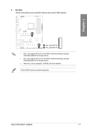
The M.2 SSD module is populated , SATA6G_5/6 will be disabled. A A M.2_1(SOCKET3) B B M.2_2(SOCKET3) • M.2_1 slot supports PCIe 4.0 x4 and SATA modes Key M design and type 2242/2260 /2280/22110 storage devices. • M.2_2 slot supports PCIe 3.0 x4 and SATA modes Key M design and type 2242/2260/2280/ 22110 storage devices. • When M.2_2 slot is purchased separately. M.2 slots The M.2 slots allow you to install M.2 devices such as M.2 SSD modules. Chapter 1 6. ROG STRIX B550-F GAMING 1-11
The M.2 SSD module is populated , SATA6G_5/6 will be disabled. A A M.2_1(SOCKET3) B B M.2_2(SOCKET3) • M.2_1 slot supports PCIe 4.0 x4 and SATA modes Key M design and type 2242/2260 /2280/22110 storage devices. • M.2_2 slot supports PCIe 3.0 x4 and SATA modes Key M design and type 2242/2260/2280/ 22110 storage devices. • When M.2_2 slot is purchased separately. M.2 slots The M.2 slots allow you to install M.2 devices such as M.2 SSD modules. Chapter 1 6. ROG STRIX B550-F GAMING 1-11
Users Manual English
Page 27
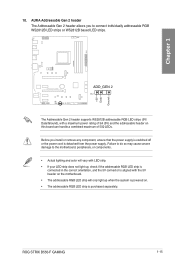
... severe damage to connect individually addressable RGB WS2812B LED strips or WS2812B based LED strips. AURA Addressable Gen 2 header The Addressable Gen 2 header allows you install or remove any component, ensure that the power supply is switched off or the power cord is purchased separately. +5V Data Ground Chapter 1 10. ADD_GEN... board can handle a combined maximum of 3A (5V) and the addressable header on . • The addressable RGB LED strip is detached from the power supply. ROG STRIX B550-F GAMING 1-15
... severe damage to connect individually addressable RGB WS2812B LED strips or WS2812B based LED strips. AURA Addressable Gen 2 header The Addressable Gen 2 header allows you install or remove any component, ensure that the power supply is switched off or the power cord is purchased separately. +5V Data Ground Chapter 1 10. ADD_GEN... board can handle a combined maximum of 3A (5V) and the addressable header on . • The addressable RGB LED strip is detached from the power supply. ROG STRIX B550-F GAMING 1-15

Users Manual English
Page 28
... rating of 3A (12V). Failure to do so may cause severe damage to connect RGB LED strips. AURA RGB headers The RGB headers allow you install or remove any component, ensure that the power supply is switched off or the power cord is purchased separately. 1-16 Chapter 1: Product Introduction Chapter 1 11...
... rating of 3A (12V). Failure to do so may cause severe damage to connect RGB LED strips. AURA RGB headers The RGB headers allow you install or remove any component, ensure that the power supply is switched off or the power cord is purchased separately. 1-16 Chapter 1: Product Introduction Chapter 1 11...
Users Manual English
Page 35
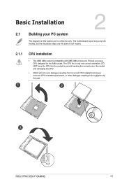
.... The CPU fits in this section are the same for all models. 2.1.1 1 CPU installation • The AMD AM4 socket is compatible with models, but the installation steps are for the AM4 socket. DO NOT force the CPU into the socket to prevent...the socket and damaging the CPU! • ASUS will not cover damages resulting from incorrect CPU installation/removal, incorrect CPU orientation/placement, or other damages resulting from negligence by the user. 2 3 ROG STRIX B550-F GAMING 2-1 Chapter 2 Chapter 2: Basic Installation Basic Installation 2 2.1 Building your PC system The diagrams in...
.... The CPU fits in this section are the same for all models. 2.1.1 1 CPU installation • The AMD AM4 socket is compatible with models, but the installation steps are for the AM4 socket. DO NOT force the CPU into the socket to prevent...the socket and damaging the CPU! • ASUS will not cover damages resulting from incorrect CPU installation/removal, incorrect CPU orientation/placement, or other damages resulting from negligence by the user. 2 3 ROG STRIX B550-F GAMING 2-1 Chapter 2 Chapter 2: Basic Installation Basic Installation 2 2.1 Building your PC system The diagrams in...

Users Manual English
Page 36
CPU Heatsink and fan assembly Type 1 1 2 Chapter 2 3 5 2-2 4 Chapter 2: Basic Installation 2.1.2 Cooling system installation Apply the Thermal Interface Material to the CPU heatsink and CPU before you install the heatsink and fan if necessary.
CPU Heatsink and fan assembly Type 1 1 2 Chapter 2 3 5 2-2 4 Chapter 2: Basic Installation 2.1.2 Cooling system installation Apply the Thermal Interface Material to the CPU heatsink and CPU before you install the heatsink and fan if necessary.

Users Manual English
Page 38
Chapter 2 AIO_PUMP CPU_FAN CPU_OPT 2-4 Chapter 2: Basic Installation To install an AIO cooler If you wish to install an AIO cooler, we recommend installing the AIO cooler after installing the motherboard into the chassis.
Chapter 2 AIO_PUMP CPU_FAN CPU_OPT 2-4 Chapter 2: Basic Installation To install an AIO cooler If you wish to install an AIO cooler, we recommend installing the AIO cooler after installing the motherboard into the chassis.

Users Manual English
Page 39
2.1.3 DIMM installation Chapter 2 To remove a DIMM ROG STRIX B550-F GAMING 2-5
2.1.3 DIMM installation Chapter 2 To remove a DIMM ROG STRIX B550-F GAMING 2-5

Users Manual English
Page 40
2.1.4 M.2 installation 1 2 1 Chapter 2 3 OPTIONAL 5 4 4 • The M.2 rubber pad is compatible with double sided M.2 storage devices. 2-6 Chapter 2: Basic Installation The rubber pad installed by default is optional for when installing a single sided M.2 storage device. Ensure to install the bundled M.2 rubber pad before installing your single sided M.2 storage device. • DO NOT install the bundled M.2 rubber pads when installing a double-sided M.2 storage device.
2.1.4 M.2 installation 1 2 1 Chapter 2 3 OPTIONAL 5 4 4 • The M.2 rubber pad is compatible with double sided M.2 storage devices. 2-6 Chapter 2: Basic Installation The rubber pad installed by default is optional for when installing a single sided M.2 storage device. Ensure to install the bundled M.2 rubber pad before installing your single sided M.2 storage device. • DO NOT install the bundled M.2 rubber pads when installing a double-sided M.2 storage device.

Users Manual English
Page 42
Chapter 2 DO NOT over tighten the screws! 2.1.5 Motherboard installation 1. Doing so can damage the motherboard. 2-8 Chapter 2: Basic Installation Place nine (9) screws into the chassis, ensuring that its rear I /O panel. 2. Place the motherboard into the holes indicated by circles to secure the motherboard to the chassis' rear I /O ports are aligned to the chassis.
Chapter 2 DO NOT over tighten the screws! 2.1.5 Motherboard installation 1. Doing so can damage the motherboard. 2-8 Chapter 2: Basic Installation Place nine (9) screws into the chassis, ensuring that its rear I /O panel. 2. Place the motherboard into the holes indicated by circles to secure the motherboard to the chassis' rear I /O ports are aligned to the chassis.

Users Manual English
Page 44
Chapter 2 2-10 Chapter 2: Basic Installation Push the connector until it clicks into place. 2.1.8 Front I/O connector To install front panel connector To install front panel audio connector AAFP To install USB 3.2 Gen 1 connector To install USB 2.0 connector USB 3.2 Gen 1 USB 2.0 This connector will only fit in one orientation.
Chapter 2 2-10 Chapter 2: Basic Installation Push the connector until it clicks into place. 2.1.8 Front I/O connector To install front panel connector To install front panel audio connector AAFP To install USB 3.2 Gen 1 connector To install USB 2.0 connector USB 3.2 Gen 1 USB 2.0 This connector will only fit in one orientation.


