User Guide
Page 16
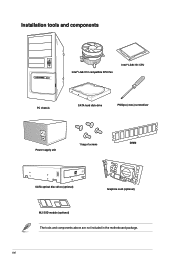
xvi Installation tools and components Intel® LGA1151 compatible CPU Fan Intel® LGA1151 CPU PC chassis SATA hard disk drive Phillips (cross) screwdriver Power supply unit 1 bag of screws DIMM SATA optical disc drive (optional) Graphics card (optional) M.2 SSD module (optional) The tools and components above are not included in the motherboard package.
xvi Installation tools and components Intel® LGA1151 compatible CPU Fan Intel® LGA1151 CPU PC chassis SATA hard disk drive Phillips (cross) screwdriver Power supply unit 1 bag of screws DIMM SATA optical disc drive (optional) Graphics card (optional) M.2 SSD module (optional) The tools and components above are not included in the motherboard package.
User Guide
Page 19
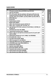
...pin W_IN; 2-pin W_OUT; 3-pin W_FLOW) 14. System panel connectors (10-1 pin F_PANEL; 4-pin SPEAKER) 15. Safe Boot button (SAFE_BOOT) 22. LGA1151 CPU Socket 3. CPU, CPU optional, high amp, extension, water pump+, AIO pump, and chassis fan connectors (4-pin CPU_FAN; 4-pin CPU_OPT; 4-pin ...1-5 1-14 1-9 1-9 1-16 1-17 1-15 1-14 1-18 1-26 1-21 1-25 1-12 1-18 1-24 1-23 1-10 1-11 1-11 1-16 1-22 1-22 ROG MAXIMUS X FORMULA 1-3 Addressable RGB header (4-pin ADD_HEADER1-2) 19. ATX power connectors (24-pin EATXPWR; 8-pin EATX12V) 2. LN2 Mode jumper (3-pin LN2_MODE) 12. AURA RGB headers (4-pin...
...pin W_IN; 2-pin W_OUT; 3-pin W_FLOW) 14. System panel connectors (10-1 pin F_PANEL; 4-pin SPEAKER) 15. Safe Boot button (SAFE_BOOT) 22. LGA1151 CPU Socket 3. CPU, CPU optional, high amp, extension, water pump+, AIO pump, and chassis fan connectors (4-pin CPU_FAN; 4-pin CPU_OPT; 4-pin ...1-5 1-14 1-9 1-9 1-16 1-17 1-15 1-14 1-18 1-26 1-21 1-25 1-12 1-18 1-24 1-23 1-10 1-11 1-11 1-16 1-22 1-22 ROG MAXIMUS X FORMULA 1-3 Addressable RGB header (4-pin ADD_HEADER1-2) 19. ATX power connectors (24-pin EATXPWR; 8-pin EATX12V) 2. LN2 Mode jumper (3-pin LN2_MODE) 12. AURA RGB headers (4-pin...
User Guide
Page 20
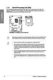
...memory and PCI Express controllers integrated to the PnP cap/socket contacts/motherboard components. Chapter 1 Ensure that the PnP cap is on the LGA1151 socket. • The product warranty does not cover damage to the socket contacts resulting from incorrect CPU installation/removal, or misplacement/loss/...if the damage is missing, or if you install the correct CPU designed for LGA1150, LGA1155, and LGA1156 sockets in the LGA1151 socket. • Ensure that all power cables are not bent. ASUS will shoulder the cost of the PnP cap. 1-4 Chapter 1: Product Introduction
...memory and PCI Express controllers integrated to the PnP cap/socket contacts/motherboard components. Chapter 1 Ensure that the PnP cap is on the LGA1151 socket. • The product warranty does not cover damage to the socket contacts resulting from incorrect CPU installation/removal, or misplacement/loss/...if the damage is missing, or if you install the correct CPU designed for LGA1150, LGA1155, and LGA1156 sockets in the LGA1151 socket. • Ensure that all power cables are not bent. ASUS will shoulder the cost of the PnP cap. 1-4 Chapter 1: Product Introduction
User Guide
Page 43
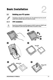
Chapter 2 Top of CPU Bottom of CPU ROG MAXIMUS X FORMULA Bottom of CPU 2-1 The motherboard layout may vary with models, but the installation steps are for reference only. DO NOT install a CPU designed for LGA1151 socket only. CPU installation Ensure that you install the correct CPU designed for LGA1155 and LGA1156 sockets on the LGA1151 socket. Chapter 2: Basic Installation Basic Installation 2.1 Building your PC system 2 2.1.1 The diagrams in this section are the same for all models.
Chapter 2 Top of CPU Bottom of CPU ROG MAXIMUS X FORMULA Bottom of CPU 2-1 The motherboard layout may vary with models, but the installation steps are for reference only. DO NOT install a CPU designed for LGA1151 socket only. CPU installation Ensure that you install the correct CPU designed for LGA1155 and LGA1156 sockets on the LGA1151 socket. Chapter 2: Basic Installation Basic Installation 2.1 Building your PC system 2 2.1.1 The diagrams in this section are the same for all models.
User Guide
Page 44
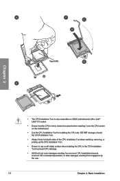
... Tool. • Always firmly hold both sides of CPU Chapter 2 • The CPU Installation Tool is only compatible on ASUS motherboards with a Intel® LGA1151 socket. • Ensure that the CPU is firmly clicked into place before installing it onto the CPU socket on the motherboard..... • Ensure to use a soft stable surface when installing the CPU to the CPU Installation Tool to prevent CPU damage. • ASUS will not cover damages resulting from incorrect CPU installation/removal, incorrect CPU orientation/placement, or other damages resulting from negligence by the user. 2-2...
... Tool. • Always firmly hold both sides of CPU Chapter 2 • The CPU Installation Tool is only compatible on ASUS motherboards with a Intel® LGA1151 socket. • Ensure that the CPU is firmly clicked into place before installing it onto the CPU socket on the motherboard..... • Ensure to use a soft stable surface when installing the CPU to the CPU Installation Tool to prevent CPU damage. • ASUS will not cover damages resulting from incorrect CPU installation/removal, incorrect CPU orientation/placement, or other damages resulting from negligence by the user. 2-2...