User Guide
Page 3
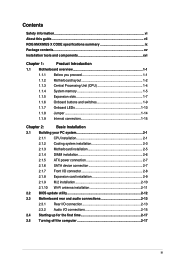
Contents Safety information...vi About this guide...vii ROG MAXIMUS X CODE specifications summary ix Package contents...xv Installation tools and components xvi Chapter 1: ...1-15 Chapter 2: Basic Installation 2.1 Building your PC system 2-1 2.1.1 CPU installation 2-1 2.1.2 Cooling system installation 2-3 2.1.3 Motherboard installation 2-5 2.1.4 DIMM installation 2-6 2.1.5 ATX power connection 2-7 2.1.6 SATA device connection 2-7 2.1.7 Front I/O connector 2-8 2.1.8 Expansion card installation 2-9 2.1.9 M.2 installation 2-10 2.1.10 Wi-Fi antenna installation 2-11 ...
Contents Safety information...vi About this guide...vii ROG MAXIMUS X CODE specifications summary ix Package contents...xv Installation tools and components xvi Chapter 1: ...1-15 Chapter 2: Basic Installation 2.1 Building your PC system 2-1 2.1.1 CPU installation 2-1 2.1.2 Cooling system installation 2-3 2.1.3 Motherboard installation 2-5 2.1.4 DIMM installation 2-6 2.1.5 ATX power connection 2-7 2.1.6 SATA device connection 2-7 2.1.7 Front I/O connector 2-8 2.1.8 Expansion card installation 2-9 2.1.9 M.2 installation 2-10 2.1.10 Wi-Fi antenna installation 2-11 ...
User Guide
Page 14
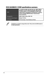
...ROG MAXIMUS X CODE specifications summary BIOS Manageability Operating System Support Form Factor 1 x 128 Mb Flash ROM, UEFI AMI BIOS, PnP, DMI3.0, WfM2.0, SM BIOS 3.0, ACPI 6.0, Multi-language BIOS, ASUS EZ Flash 3, CrashFree BIOS 3, F11 EZ Tuning Wizard, F6 Qfan Control, F3 My Favorites, Last Modified log, F12 PrintScreen, F3 Shortcut functions and ASUS... DRAM SPD (Serial Presence Detect) memory information. WfM2.0, DMI3.0, WOL by PME, PXE Windows® 10 64-bit ATX Form Factor, 12"x 9.6" (30.5cm x 24.4cm) Specifications are subject to the ASUS website for the ...
...ROG MAXIMUS X CODE specifications summary BIOS Manageability Operating System Support Form Factor 1 x 128 Mb Flash ROM, UEFI AMI BIOS, PnP, DMI3.0, WfM2.0, SM BIOS 3.0, ACPI 6.0, Multi-language BIOS, ASUS EZ Flash 3, CrashFree BIOS 3, F11 EZ Tuning Wizard, F6 Qfan Control, F3 My Favorites, Last Modified log, F12 PrintScreen, F3 Shortcut functions and ASUS... DRAM SPD (Serial Presence Detect) memory information. WfM2.0, DMI3.0, WOL by PME, PXE Windows® 10 64-bit ATX Form Factor, 12"x 9.6" (30.5cm x 24.4cm) Specifications are subject to the ASUS website for the ...
User Guide
Page 17
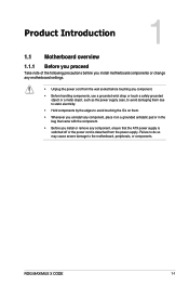
ROG MAXIMUS X CODE 1-1 Failure to do so may cause severe damage to avoid touching the ICs on them. • Whenever you uninstall any component, place it on a grounded antistatic pad or in the bag that came with the component. • Before you install or remove any component, ensure that the ATX power supply is switched...
ROG MAXIMUS X CODE 1-1 Failure to do so may cause severe damage to avoid touching the ICs on them. • Whenever you uninstall any component, place it on a grounded antistatic pad or in the bag that came with the component. • Before you install or remove any component, ensure that the ATX power supply is switched...
User Guide
Page 19
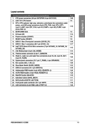
..., and water flow connectors (2-pin W_IN; 2-pin W_OUT; 3-pin W_FLOW) 14. M.2 sockets (M.2_1; AURA RGB headers (4-pin RGB_HEADER1-2) 20. MemOK! ATX power connectors (24-pin EATXPWR; 8-pin EATX12V) 2. Power-on button (START) 7. M.2_2) 16. Front panel audio connector (10-1 pin AAFP) ...1-19 1-5 1-14 1-9 1-9 1-16 1-17 1-15 1-14 1-18 1-22 1-21 1-25 1-12 1-18 1-24 1-23 1-10 1-11 1-11 1-16 1-22 ROG MAXIMUS X CODE 1-3 Addressable RGB header (4-pin ADD_HEADER1-2) 19. ReTry button (RETRY_BUTTON) 23. LGA1151 CPU Socket 3. RESET button (RESET) 8. System panel connectors (10-1 pin F_PANEL; 4-...
..., and water flow connectors (2-pin W_IN; 2-pin W_OUT; 3-pin W_FLOW) 14. M.2 sockets (M.2_1; AURA RGB headers (4-pin RGB_HEADER1-2) 20. MemOK! ATX power connectors (24-pin EATXPWR; 8-pin EATX12V) 2. Power-on button (START) 7. M.2_2) 16. Front panel audio connector (10-1 pin AAFP) ...1-19 1-5 1-14 1-9 1-9 1-16 1-17 1-15 1-14 1-18 1-22 1-21 1-25 1-12 1-18 1-24 1-23 1-10 1-11 1-11 1-16 1-22 ROG MAXIMUS X CODE 1-3 Addressable RGB header (4-pin ADD_HEADER1-2) 19. ReTry button (RETRY_BUTTON) 23. LGA1151 CPU Socket 3. RESET button (RESET) 8. System panel connectors (10-1 pin F_PANEL; 4-...
User Guide
Page 36
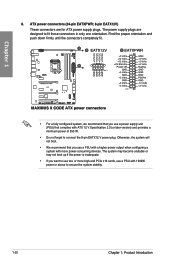
... the connectors completely fit. • For a fully configured system, we recommend that you use a power supply unit (PSU) that you want to use a PSU with ATX 12 V Specification 2.0 (or later version) and provides a minimum power of 350 W. • Do not forget to fit these connectors in only one orientation...
... the connectors completely fit. • For a fully configured system, we recommend that you use a power supply unit (PSU) that you want to use a PSU with ATX 12 V Specification 2.0 (or later version) and provides a minimum power of 350 W. • Do not forget to fit these connectors in only one orientation...
User Guide
Page 37
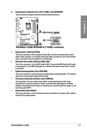
The HDD LED lights up when you to this connector. ROG MAXIMUS X CODE 1-21 9. Chapter 1 • System power LED (2-pin PLED) This 2-pin connector is for the chassis-mounted system warning speaker. Connect the chassis power LED cable to hear system beeps and warnings. • ATX power button/soft-off the system power. Connect the...
The HDD LED lights up when you to this connector. ROG MAXIMUS X CODE 1-21 9. Chapter 1 • System power LED (2-pin PLED) This 2-pin connector is for the chassis-mounted system warning speaker. Connect the chassis power LED cable to hear system beeps and warnings. • ATX power button/soft-off the system power. Connect the...
User Guide
Page 39
... will vary with LED strips. • If your LED strip does not light up when the system is detached from the power supply. Chapter 1 12. ROG MAXIMUS X CODE 1-23 Failure to do so may cause severe damage to the motherboard, peripherals, or components. • Actual lighting and color will only light up , check... 12V connector is aligned with a maximum power rating of 3A (12V), and no longer than 3 m. Before you install or remove any component, ensure that the ATX power supply is switched off or the power cord is operating. • The LED strips are for RGB LED strips.
... will vary with LED strips. • If your LED strip does not light up when the system is detached from the power supply. Chapter 1 12. ROG MAXIMUS X CODE 1-23 Failure to do so may cause severe damage to the motherboard, peripherals, or components. • Actual lighting and color will only light up , check... 12V connector is aligned with a maximum power rating of 3A (12V), and no longer than 3 m. Before you install or remove any component, ensure that the ATX power supply is switched off or the power cord is operating. • The LED strips are for RGB LED strips.
User Guide
Page 40
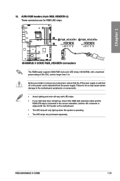
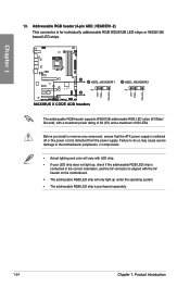
... aligned with a maximum power rating of 3A (5V) and a maximum of 60 LEDs. Chapter 1 13. Before you install or remove any component, ensure that the ATX power supply is switched off or the power cord is detached from the power supply. The addressable RGB header supports WS2812B addressable RGB LED strips...
... aligned with a maximum power rating of 3A (5V) and a maximum of 60 LEDs. Chapter 1 13. Before you install or remove any component, ensure that the ATX power supply is switched off or the power cord is detached from the power supply. The addressable RGB header supports WS2812B addressable RGB LED strips...
User Guide
Page 49
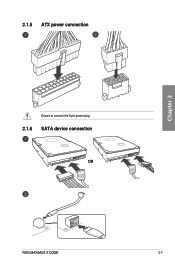
2.1.5 ATX power connection Chapter 2 Ensure to connect the 8-pin power plug. 2.1.6 SATA device connection OR ROG MAXIMUS X CODE 2-7
2.1.5 ATX power connection Chapter 2 Ensure to connect the 8-pin power plug. 2.1.6 SATA device connection OR ROG MAXIMUS X CODE 2-7
User Guide
Page 59
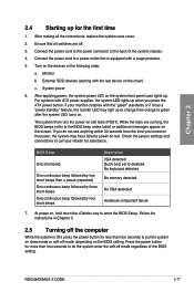
...seconds from the time you press the ATX power button. Follow the instructions in the following order: a. Chapter 2 2.4 Starting up for more than four seconds to green after the system LED turns on the system front panel case lights up. ROG MAXIMUS X CODE 2-17 After making all switches are running..., the BIOS beeps (refer to the BIOS beep codes table) or additional messages appear on , hold down the key to enter the BIOS Setup...
...seconds from the time you press the ATX power button. Follow the instructions in the following order: a. Chapter 2 2.4 Starting up for more than four seconds to green after the system LED turns on the system front panel case lights up. ROG MAXIMUS X CODE 2-17 After making all switches are running..., the BIOS beeps (refer to the BIOS beep codes table) or additional messages appear on , hold down the key to enter the BIOS Setup...

