Users Manual English
Page 2
... Free Open Source Software licenses. ASUS ASSUMES NO RESPONSIBILITY OR LIABILITY FOR ANY ERRORS OR INACCURACIES THAT MAY APPEAR IN THIS MANUAL, INCLUDING THE PRODUCTS AND SOFTWARE DESCRIBED IN IT. Product warranty or service will be extended if: (1) the product is repaired, modified or altered, unless such repair, modification of alteration is dependent on the preferred carrier and the location...
... Free Open Source Software licenses. ASUS ASSUMES NO RESPONSIBILITY OR LIABILITY FOR ANY ERRORS OR INACCURACIES THAT MAY APPEAR IN THIS MANUAL, INCLUDING THE PRODUCTS AND SOFTWARE DESCRIBED IN IT. Product warranty or service will be extended if: (1) the product is repaired, modified or altered, unless such repair, modification of alteration is dependent on the preferred carrier and the location...
Users Manual English
Page 3
Contents Safety information iv About this guide iv Package contents vi PRIME H310M-E specifications summary vi Chapter 1: Product introduction Motherboard overview 1-1 Central Processing Unit (CPU 1-7 System memory 1-8 M.2 Anchor Installation 1-9 Chapter 2: BIOS information BIOS setup program 2-1 EZ Mode...2-2 Advanced Mode 2-3 Exit menu...2-4 Appendix Notices...A-1 ASUS contact information A-5 iii
Contents Safety information iv About this guide iv Package contents vi PRIME H310M-E specifications summary vi Chapter 1: Product introduction Motherboard overview 1-1 Central Processing Unit (CPU 1-7 System memory 1-8 M.2 Anchor Installation 1-9 Chapter 2: BIOS information BIOS setup program 2-1 EZ Mode...2-2 Advanced Mode 2-3 Exit menu...2-4 Appendix Notices...A-1 ASUS contact information A-5 iii

Users Manual English
Page 4
... before you add a device. • Before connecting or removing signal cables from the motherboard, ensure that all power cables are connected. If possible, disconnect all power cables from the existing system before using , contact your local power company. • If the power supply is organized This guide contains the following parts: • Chapter 1: Product introduction This chapter describes the features of the switches, jumpers, and connectors on a stable surface...
... before you add a device. • Before connecting or removing signal cables from the motherboard, ensure that all power cables are connected. If possible, disconnect all power cables from the existing system before using , contact your local power company. • If the power supply is organized This guide contains the following parts: • Chapter 1: Product introduction This chapter describes the features of the switches, jumpers, and connectors on a stable surface...
Users Manual English
Page 6
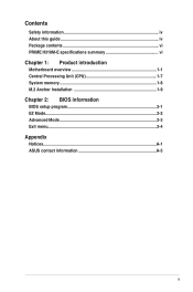
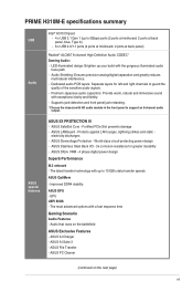
...Storage LAN Intel® H310 Chipset: - 1 x M.2 Socket 3 with M Key, type 2242/2260/2280 storage devices support (SATA mode & x2 PCIE mode)* - 4 x SATA 6.0 Gb/s ports (gray) * When a SATA mode M.2 device is set to www.asus.com for the following items. Motherboard Cables Accessories Application DVD Documentation ASUS PRIME H310M-E motherboard 2 x Serial ATA 6.0 Gb/s cables 1 x ASUS I/O Shield 1 x M.2 Anchor Support DVD User Guide If any of the above items are damaged or missing, contact your motherboard package for Intel® CPU support list. Realtek® 8111H Gigabit LAN supports...
...Storage LAN Intel® H310 Chipset: - 1 x M.2 Socket 3 with M Key, type 2242/2260/2280 storage devices support (SATA mode & x2 PCIE mode)* - 4 x SATA 6.0 Gb/s ports (gray) * When a SATA mode M.2 device is set to www.asus.com for the following items. Motherboard Cables Accessories Application DVD Documentation ASUS PRIME H310M-E motherboard 2 x Serial ATA 6.0 Gb/s cables 1 x ASUS I/O Shield 1 x M.2 Anchor Support DVD User Guide If any of the above items are damaged or missing, contact your motherboard package for Intel® CPU support list. Realtek® 8111H Gigabit LAN supports...
Users Manual English
Page 7
... panel, blue, Type A) - 6 x USB 2.0/1.1 ports (4 ports at mid-board; 2 ports at back panel) Realtek® ALC887 8-channel High Definition Audio CODEC* Gaming Audio: - EPU UEFI BIOS - ASUS PC Cleaner (continued on the battlefield ASUS Exclusive Features - PRIME H310M-E specifications summary USB Audio Intel® H310 Chipset: - 4 x USB 3.1 Gen 1 (up to support an 8-channel audio output. Supports jack-detection and front panel jack-retasking. * Choose the chassis with HD audio module in the front panel to 10 GB/s data transfer speeds ASUS OptiMem - Fortified PCIe Slot...
... panel, blue, Type A) - 6 x USB 2.0/1.1 ports (4 ports at mid-board; 2 ports at back panel) Realtek® ALC887 8-channel High Definition Audio CODEC* Gaming Audio: - EPU UEFI BIOS - ASUS PC Cleaner (continued on the battlefield ASUS Exclusive Features - PRIME H310M-E specifications summary USB Audio Intel® H310 Chipset: - 4 x USB 3.1 Gen 1 (up to support an 8-channel audio output. Supports jack-detection and front panel jack-retasking. * Choose the chassis with HD audio module in the front panel to 10 GB/s data transfer speeds ASUS OptiMem - Fortified PCIe Slot...
Users Manual English
Page 8
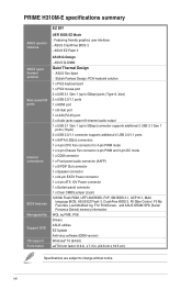
... Design: PCH heatsink solution 1 x PS/2 keyboard port 1 x PS/2 mouse port 2 x USB 3.1 Gen 1 (up to 5Gbps) ports (Type-A, blue) 2 x USB 2.0/1.1 ports 1 x HDMI port 1 x D-Sub port 1 x LAN (RJ-45) port 3 x Audio jacks support 8-channel audio output 1 x USB 3.1 Gen 1 (up to change without notice. language BIOS, ASUS EZ Flash 3, CrashFree BIOS 3, F6 Qfan Control, F3 My Favorites, Last Modified log, F12 PrintScreen, and ASUS DRAM SPD (Serial Presence Detect) memory information WOL by PME, PXE Drivers ASUS utilities EZ Update Anti-virus software (OEM version) Windows® 10 (64-bit) uATX...
... Design: PCH heatsink solution 1 x PS/2 keyboard port 1 x PS/2 mouse port 2 x USB 3.1 Gen 1 (up to 5Gbps) ports (Type-A, blue) 2 x USB 2.0/1.1 ports 1 x HDMI port 1 x D-Sub port 1 x LAN (RJ-45) port 3 x Audio jacks support 8-channel audio output 1 x USB 3.1 Gen 1 (up to change without notice. language BIOS, ASUS EZ Flash 3, CrashFree BIOS 3, F6 Qfan Control, F3 My Favorites, Last Modified log, F12 PrintScreen, and ASUS DRAM SPD (Serial Presence Detect) memory information WOL by PME, PXE Drivers ASUS utilities EZ Update Anti-virus software (OEM version) Windows® 10 (64-bit) uATX...
Users Manual English
Page 9
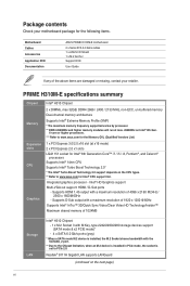
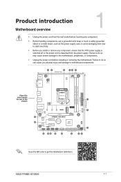
...,288-pin module) EATXPWR 22.6cm(8.9in) Place this side towards the rear of the chassis HDMI LGA1151 U31G1_34 1 CHA_FAN LAN_USB56 M.2(SOCKET3) PCIE SATA IRST X2 V X AUDIO 2280 Realtek 8111H 2260 2242 PCIEX16 SATA6G_1 16 16 PRIME H310M-E Super I/O PCIEX1_1 15 BATTERY Intel® 128Mb H310 BIOS ALC 887 PCIEX1_2 SPDIF_OUT COM USB914 USB78 U31G1_12 SATA6G_4 SATA6G_3 SATA6G_2 SPEAKER 17 AAFP...
...,288-pin module) EATXPWR 22.6cm(8.9in) Place this side towards the rear of the chassis HDMI LGA1151 U31G1_34 1 CHA_FAN LAN_USB56 M.2(SOCKET3) PCIE SATA IRST X2 V X AUDIO 2280 Realtek 8111H 2260 2242 PCIEX16 SATA6G_1 16 16 PRIME H310M-E Super I/O PCIEX1_1 15 BATTERY Intel® 128Mb H310 BIOS ALC 887 PCIEX1_2 SPDIF_OUT COM USB914 USB78 U31G1_12 SATA6G_4 SATA6G_3 SATA6G_2 SPEAKER 17 AAFP...

Users Manual English
Page 10
... power output when configuring a system with ATX 12 V Specification 2.0 (or later version) and provides a minimum power of the connector. Do not place jumper caps on the M.2 socket, the SATA_2 port cannot be used. • Due to the Chipset limitation, when an M.2 device is installed in PCIe mode, the socket is installed on the fan connectors! The CPU_FAN connector supports a CPU fan of maximum 0.5A (6 W) fan power. M.2(SOCKET3) • This M.2 socket supports M Key and 2242/2260/2280 storage devices. • When a device in SATA mode...
... power output when configuring a system with ATX 12 V Specification 2.0 (or later version) and provides a minimum power of the connector. Do not place jumper caps on the M.2 socket, the SATA_2 port cannot be used. • Due to the Chipset limitation, when an M.2 device is installed in PCIe mode, the socket is installed on the fan connectors! The CPU_FAN connector supports a CPU fan of maximum 0.5A (6 W) fan power. M.2(SOCKET3) • This M.2 socket supports M Key and 2242/2260/2280 storage devices. • When a device in SATA mode...
Users Manual English
Page 11
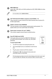
... the power cord. 2. Hold down the key during the boot process and enter BIOS setup to re-enter data. +3V_BAT GND CLRTC PIN 1 If the steps above do not help, remove the onboard battery and short the two pins again to Serial ATA 6.0 Gb/s hard disk drives via Serial ATA 6.0 Gb/s signal cables. System panel connector (10-1 pin F_PANEL) This connector supports several chassis-mounted functions. Clear RTC RAM (2-pin CLRTC) This header allows you to clear the CMOS RTC RAM data...
... the power cord. 2. Hold down the key during the boot process and enter BIOS setup to re-enter data. +3V_BAT GND CLRTC PIN 1 If the steps above do not help, remove the onboard battery and short the two pins again to Serial ATA 6.0 Gb/s hard disk drives via Serial ATA 6.0 Gb/s signal cables. System panel connector (10-1 pin F_PANEL) This connector supports several chassis-mounted functions. Clear RTC RAM (2-pin CLRTC) This header allows you to clear the CMOS RTC RAM data...

Users Manual English
Page 12
... USB 2.0. PCI Express 2.0 x1 slots This motherboard has two PCI Express 2.0 x1 slots that support PCI Express x1 network cards, SCSI cards, and other cards that complies with the PCI Express specifications. Digital audio connector (4-1 pin SPDIF_OUT) Connect the S/PDIF Out module cable to this connector, then install the module to a slot opening at the back of up to 5 Gbps, faster charging time for USB-chargeable devices, optimized power efficiency, and backward compatibility with USB 2.0 specifications and supports up to 5Gb/s) connector (20-1 pin U31G1_12) Connect a USB...
... USB 2.0. PCI Express 2.0 x1 slots This motherboard has two PCI Express 2.0 x1 slots that support PCI Express x1 network cards, SCSI cards, and other cards that complies with the PCI Express specifications. Digital audio connector (4-1 pin SPDIF_OUT) Connect the S/PDIF Out module cable to this connector, then install the module to a slot opening at the back of up to 5 Gbps, faster charging time for USB-chargeable devices, optimized power efficiency, and backward compatibility with USB 2.0 specifications and supports up to 5Gb/s) connector (20-1 pin U31G1_12) Connect a USB...
Users Manual English
Page 13
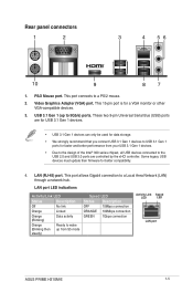
...two 9-pin Universal Serial Bus (USB) ports are controlled by the xHCI controller. This port connects to the USB 2.0 and USB 3.0 ports are for USB 3.1 Gen 1 devices. • USB 3.1 Gen 1 devices can only be used for data storage. • We strongly recommend that you connect USB 3.1 Gen 1 devices to USB 3.1 Gen 1 ports for faster and better performance from S5 mode Speed LED Status Description OFF 10Mbps connection ORANGE 100Mbps connection GREEN 1Gbps connection Activity Link Speed LED LED LAN port ASUS PRIME H310M-E 1-5 Some legacy USB devices must update their firmware...
...two 9-pin Universal Serial Bus (USB) ports are controlled by the xHCI controller. This port connects to the USB 2.0 and USB 3.0 ports are for USB 3.1 Gen 1 devices. • USB 3.1 Gen 1 devices can only be used for data storage. • We strongly recommend that you connect USB 3.1 Gen 1 devices to USB 3.1 Gen 1 ports for faster and better performance from S5 mode Speed LED Status Description OFF 10Mbps connection ORANGE 100Mbps connection GREEN 1Gbps connection Activity Link Speed LED LED LAN port ASUS PRIME H310M-E 1-5 Some legacy USB devices must update their firmware...

Users Manual English
Page 14
... panel) Lime (Rear panel) Pink (Rear panel) Lime (Front panel) Headset 2.1-channel 4.1-channel Line In Rear Speaker Out Line Out Mic In - This port connects to support a 7.1-channel audio output. 8. USB 2.0 ports. Line In port (light blue). 5. This port connects to the audio configuration table for USB 2.0/1.1 devices. 9. Microphone port (pink). Front Speaker Out Mic In - 5.1-channel Rear Speaker Out Front Speaker Out Bass/Center - 7.1-channel Rear Speaker Out Front Speaker Out Bass/Center Side Speaker Out To configure a 7.1-channel audio output: Use a chassis with HD audio...
... panel) Lime (Rear panel) Pink (Rear panel) Lime (Front panel) Headset 2.1-channel 4.1-channel Line In Rear Speaker Out Line Out Mic In - This port connects to support a 7.1-channel audio output. 8. USB 2.0 ports. Line In port (light blue). 5. This port connects to the audio configuration table for USB 2.0/1.1 devices. 9. Microphone port (pink). Front Speaker Out Mic In - 5.1-channel Rear Speaker Out Front Speaker Out Bass/Center - 7.1-channel Rear Speaker Out Front Speaker Out Bass/Center Side Speaker Out To configure a 7.1-channel audio output: Use a chassis with HD audio...
Users Manual English
Page 15
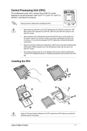
...; Core™ i7 / Core™ i5 / Core™ i3, Pentium®, and Celeron® processors. Contact your retailer immediately if the PnP cap is missing, or if you install the correct CPU designed for LGA1150, LGA1155 and LGA1156 sockets on the LGA1151 socket. • Upon purchase of the PnP cap. Unplug all power cables before you install the heatsink and fan if necessary. ASUS PRIME H310M-E 1-7 Installing...
...; Core™ i7 / Core™ i5 / Core™ i3, Pentium®, and Celeron® processors. Contact your retailer immediately if the PnP cap is missing, or if you install the correct CPU designed for LGA1150, LGA1155 and LGA1156 sockets on the LGA1151 socket. • Upon purchase of the PnP cap. Unplug all power cables before you install the heatsink and fan if necessary. ASUS PRIME H310M-E 1-7 Installing...

Users Manual English
Page 16
... memory modules for the dual-channel configuration. For optimal compatibility, we recommend that you install memory modules of these memory modules depend on the CPU's capabilities and other installed devices. • The default memory operation frequency is dependent on Intel® 8th Generation 6-core or higher processors. • Memory modules with memory frequency higher than the vendor-marked value. • For system stability, use a more efficient memory cooling system to support a full memory load...
... memory modules for the dual-channel configuration. For optimal compatibility, we recommend that you install memory modules of these memory modules depend on the CPU's capabilities and other installed devices. • The default memory operation frequency is dependent on Intel® 8th Generation 6-core or higher processors. • Memory modules with memory frequency higher than the vendor-marked value. • For system stability, use a more efficient memory cooling system to support a full memory load...
Users Manual English
Page 17
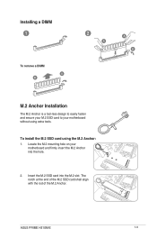
To install the M.2 SSD card using extra tools. The notch at the end of the M.2 SSD card shall align with the rod of the M.2 Anchor. Insert the M.2 SSD card into the hole. 2. Installing a DIMM 1 To remove a DIMM A B 2 A A B M.2 Anchor Installation The M.2 Anchor is a tool-less design to easily fasten and secure your M.2 SSD card to your motherboard and firmly insert the M.2 Anchor into the M.2 slot. ASUS PRIME H310M-E 1-9 Locate the M.2 mounting hole on your motherboard without using the M.2 Anchor: 1.
To install the M.2 SSD card using extra tools. The notch at the end of the M.2 SSD card shall align with the rod of the M.2 Anchor. Insert the M.2 SSD card into the hole. 2. Installing a DIMM 1 To remove a DIMM A B 2 A A B M.2 Anchor Installation The M.2 Anchor is a tool-less design to easily fasten and secure your M.2 SSD card to your motherboard and firmly insert the M.2 Anchor into the M.2 slot. ASUS PRIME H310M-E 1-9 Locate the M.2 mounting hole on your motherboard without using the M.2 Anchor: 1.
Users Manual English
Page 19
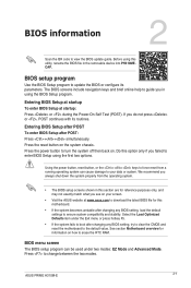
... in the removable device into PH310ME. CAP. The BIOS screens include navigation keys and brief online help to guide you see on the system chassis. Entering BIOS Setup after POST To enter BIOS Setup after changing any BIOS setting, try to clear the CMOS and reset the motherboard to ensure system compatibility and stability. Press the reset button on your data or system. Press the power button to erase the RTC RAM. Press to update the BIOS or configure its...
... in the removable device into PH310ME. CAP. The BIOS screens include navigation keys and brief online help to guide you see on the system chassis. Entering BIOS Setup after POST To enter BIOS Setup after changing any BIOS setting, try to clear the CMOS and reset the motherboard to ensure system compatibility and stability. Press the reset button on your data or system. Press the power button to erase the RTC RAM. Press to update the BIOS or configure its...

Users Manual English
Page 20
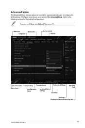
Click the button to manually tune the fans Loads optimized default settings Shows the bootable devices Saves the changes and resets the system Displays the Advanced mode menus Search on FAQs Selects the boot device priority The boot device options vary depending on the devices you to select the display language, system performance mode, fan profile and boot device priority. Displays the CPU/ motherboard temperature, CPU voltage output, CPU/ chassis fan speed, and SATA information Searches by BIOS item name, enter the item name Displays the system...
Click the button to manually tune the fans Loads optimized default settings Shows the bootable devices Saves the changes and resets the system Displays the Advanced mode menus Search on FAQs Selects the boot device priority The boot device options vary depending on the devices you to select the display language, system performance mode, fan profile and boot device priority. Displays the CPU/ motherboard temperature, CPU voltage output, CPU/ chassis fan speed, and SATA information Searches by BIOS item name, enter the item name Displays the system...
Users Manual English
Page 21
The figure below shows an example of the Advanced Mode. Refer to the following sections for experienced end-users to EZ Mode Scroll bar Searches FAQ Hot Keys Displays hardware monitoring data ASUS PRIME H310M-E 2-3 To access the EZ Mode, click EzMode(F7) or press . Menu bar MyFavorite Language Q-Fan control Search Sub-menu items Menu items General help Pop-up window Configuration fields Last modified settings Return to configure the BIOS settings. Advanced Mode The Advanced Mode provides advanced options for the detailed configurations.
The figure below shows an example of the Advanced Mode. Refer to the following sections for experienced end-users to EZ Mode Scroll bar Searches FAQ Hot Keys Displays hardware monitoring data ASUS PRIME H310M-E 2-3 To access the EZ Mode, click EzMode(F7) or press . Menu bar MyFavorite Language Q-Fan control Search Sub-menu items Menu items General help Pop-up window Configuration fields Last modified settings Return to configure the BIOS settings. Advanced Mode The Advanced Mode provides advanced options for the detailed configurations.
Users Manual English
Page 23
... or more of the monitor to radio communications. The use of shielded cables for a Class B digital device, pursuant to radio or television reception, which can radiate radio frequency energy and, if not installed and used in accordance with Part 15 of the FCC Rules. These limits are designed to assure compliance with FCC regulations. A-1 ASUS PRIME H310M-E If this equipment. Appendix...
... or more of the monitor to radio communications. The use of shielded cables for a Class B digital device, pursuant to radio or television reception, which can radiate radio frequency energy and, if not installed and used in accordance with Part 15 of the FCC Rules. These limits are designed to assure compliance with FCC regulations. A-1 ASUS PRIME H310M-E If this equipment. Appendix...
Users Manual English
Page 25
... the mercury-containing button cell battery in municipal waste. This product has been designed to in municipal waste. This symbol of the crossed out wheeled bin indicates that the product (electrical and electronic equipment) should not be placed in writing, software distributed under the Apache License, Version 2.0 (the "License"); All Rights Reserved. A-3 ASUS PRIME H310M-E Regional notice...
... the mercury-containing button cell battery in municipal waste. This product has been designed to in municipal waste. This symbol of the crossed out wheeled bin indicates that the product (electrical and electronic equipment) should not be placed in writing, software distributed under the Apache License, Version 2.0 (the "License"); All Rights Reserved. A-3 ASUS PRIME H310M-E Regional notice...


