Manual PDF file for PR-DLS533
Page 3
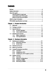
...vii About this guide viii How this guide is organized viii Conventions used in this guide ix Where to find more information ix ASUS contact information x PR-DLS533 specifications summary xi Chapter 1: Product introduction 1.1 Welcome 1-1 1.2 Package contents 1-1 1.3 Special features 1-2 1.3.1 Product highlights 1-2 1.3.2...Central Processing Unit (CPU 2-3 2.4.1 Overview 2-3 2.4.2 Installing the CPU 2-4 2.4.3 Installing the CPU heatsink and fan 2-6 2.5 System memory 2-8 2.5.1 Overview 2-8 2.5.2 Memory Configurations 2-9 2.5.3 Installing a DIMM 2-10 2.5.4 Removing a DIMM 2-10 iii
...vii About this guide viii How this guide is organized viii Conventions used in this guide ix Where to find more information ix ASUS contact information x PR-DLS533 specifications summary xi Chapter 1: Product introduction 1.1 Welcome 1-1 1.2 Package contents 1-1 1.3 Special features 1-2 1.3.1 Product highlights 1-2 1.3.2...Central Processing Unit (CPU 2-3 2.4.1 Overview 2-3 2.4.2 Installing the CPU 2-4 2.4.3 Installing the CPU heatsink and fan 2-6 2.5 System memory 2-8 2.5.1 Overview 2-8 2.5.2 Memory Configurations 2-9 2.5.3 Installing a DIMM 2-10 2.5.4 Removing a DIMM 2-10 iii
Manual PDF file for PR-DLS533
Page 11
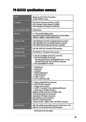
PR-DLS533 specifications summary CPU Chipsets Front Side Bus (FSB) Memory Onboard LAN Onboard SCSI Onboard VGA Expansion slots Rear panel I/O Internal connectors BIOS features Support for Intel® Xeon™ processor On-die 512KB L2 ...) RCC Champion I/O Bridge 2.0 (CIOB-X2) 400/533 MHz 6 x 184-pin DDR DIMM sockets Supports PC2100/PC1600 registered ECC DDR DIMMs Supports 128MB to 12GB system memory Intel® 82544GC 64-bit PCI-X Gigabit Ethernet controller Intel® 82540EM 32-bit PCI Gigabit Ethernet controller Intel® 82551QM Fast Ethernet controller (optional...
PR-DLS533 specifications summary CPU Chipsets Front Side Bus (FSB) Memory Onboard LAN Onboard SCSI Onboard VGA Expansion slots Rear panel I/O Internal connectors BIOS features Support for Intel® Xeon™ processor On-die 512KB L2 ...) RCC Champion I/O Bridge 2.0 (CIOB-X2) 400/533 MHz 6 x 184-pin DDR DIMM sockets Supports PC2100/PC1600 registered ECC DDR DIMMs Supports 128MB to 12GB system memory Intel® 82544GC 64-bit PCI-X Gigabit Ethernet controller Intel® 82540EM 32-bit PCI Gigabit Ethernet controller Intel® 82551QM Fast Ethernet controller (optional...

Manual PDF file for PR-DLS533
Page 16
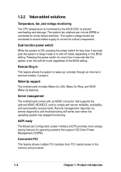
...slots onboard maximizes I /O and server management cards. DDR memory support Employing the Double Data Rate (DDR) memory technology, the PR-DLS533 motherboard supports up to 12GB of system memory using PC2100/1600 registered ECC DDR DIMMs. The ultra-fast 266MHz memory bus doubles the speed of the PC133 SDRAM to offer ... bandwidth for the latest 3D graphics, multimedia, and Internet applications. 1.3 Special features 1.3.1 Product highlights Latest processor technology The PR-DLS533 motherboard supports the Intel® Xeon processor via dual 603/604-pin surface mount ZIF sockets.
...slots onboard maximizes I /O and server management cards. DDR memory support Employing the Double Data Rate (DDR) memory technology, the PR-DLS533 motherboard supports up to 12GB of system memory using PC2100/1600 registered ECC DDR DIMMs. The ultra-fast 266MHz memory bus doubles the speed of the PC133 SDRAM to offer ... bandwidth for the latest 3D graphics, multimedia, and Internet applications. 1.3 Special features 1.3.1 Product highlights Latest processor technology The PR-DLS533 motherboard supports the Intel® Xeon processor via dual 603/604-pin surface mount ZIF sockets.
Manual PDF file for PR-DLS533
Page 18
... allows multiple PCI transfers from PCI master buses to prevent overheating and damage. Dual function power switch While the system is monitored by the ASUS ASIC to the memory and processor. 1-4 Chapter 1: Product introduction Pressing the power switch for more energy saving features for timely failure detection. The system fan rotations per...
... allows multiple PCI transfers from PCI master buses to prevent overheating and damage. Dual function power switch While the system is monitored by the ASUS ASIC to the memory and processor. 1-4 Chapter 1: Product introduction Pressing the power switch for more energy saving features for timely failure detection. The system fan rotations per...

Manual PDF file for PR-DLS533
Page 19
...consumption and system noise. A chassis intrusion event is in the system memory for more control and protection to the motherboard. Chassis intrusion detection The motherboard supports chassis intrusion monitoring through the ASUS ASIC. The BIOS has a boot block write protection and HD/...management for configuring and managing all system components, 32-bit device drivers, and installation procedures for SDG 2.0 certification. ASUS PR-DLS533 motherboard user guide 1-5 Compliance Both the BIOS and the hardware levels of the motherboard meet the stringent requirements for Windows NT/...
...consumption and system noise. A chassis intrusion event is in the system memory for more control and protection to the motherboard. Chassis intrusion detection The motherboard supports chassis intrusion monitoring through the ASUS ASIC. The BIOS has a boot block write protection and HD/...management for configuring and managing all system components, 32-bit device drivers, and installation procedures for SDG 2.0 certification. ASUS PR-DLS533 motherboard user guide 1-5 Compliance Both the BIOS and the hardware levels of the motherboard meet the stringent requirements for Windows NT/...
Manual PDF file for PR-DLS533
Page 22
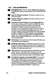
... power connector. This 5-switch Dual Inline Package (DIP) allows you to four Ultra DMA/100/66, PIO Modes 3 & 4 IDE devices. The Champion Memory and I/O Controller LE (CMIC-LE) acts as a PCI to the processor bus, and integrates the functions of the IDE ribbon cable. 8 ServerWorks®...Bus (IMB) interface unit. The processor interface supports a 533/400MHz Front Side Bus (FSB) providing a 4.26GB/s or 3.2GB/s bandwidth, 2-way interleaved memory up to set the CPU external frequency. 6 603/604-pin CPU sockets. These dual-channel bus master IDE connectors support up to 4.26GB/s or 3.2GB...
... power connector. This 5-switch Dual Inline Package (DIP) allows you to four Ultra DMA/100/66, PIO Modes 3 & 4 IDE devices. The Champion Memory and I/O Controller LE (CMIC-LE) acts as a PCI to the processor bus, and integrates the functions of the IDE ribbon cable. 8 ServerWorks®...Bus (IMB) interface unit. The processor interface supports a 533/400MHz Front Side Bus (FSB) providing a 4.26GB/s or 3.2GB/s bandwidth, 2-way interleaved memory up to set the CPU external frequency. 6 603/604-pin CPU sockets. These dual-channel bus master IDE connectors support up to 4.26GB/s or 3.2GB...
Manual PDF file for PR-DLS533
Page 26
Chapter summary 2.1 Motherboard installation 2-1 2.2 Motherboard layout 2-2 2.3 Before you proceed 2-3 2.4 Central Processing Unit (CPU 2-3 2.5 System memory 2-8 2.6 Expansion slots 2-11 2.7 Switches and jumpers 2-14 2.8 Connectors 2-18 ASUS PR-DLS533 motherboard
Chapter summary 2.1 Motherboard installation 2-1 2.2 Motherboard layout 2-2 2.3 Before you proceed 2-3 2.4 Central Processing Unit (CPU 2-3 2.5 System memory 2-8 2.6 Expansion slots 2-11 2.7 Switches and jumpers 2-14 2.8 Connectors 2-18 ASUS PR-DLS533 motherboard
Manual PDF file for PR-DLS533
Page 34
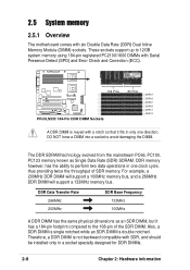
...Chapter 2: Hardware information DO NOT force a DIMM into a socket to 12GB system memory using 184-pin registered PC2100/1600 DIMMs with Serial Presence Detect (SPD) and Error Check and Correction (ECC). 104 Pins PR-DLS533 PR-DLS533 184-Pin DDR DIMM Sockets 80 Pins DDRA1 DDRA2 DDRB1 DDRB2 DDRC1 DDRC2 A DDR ...DIMM is double notched. The DDR SDRAM technology evolved from the mainstream PC66, PC100, PC133 memory known as an SDR DIMM, but it fits in...
...Chapter 2: Hardware information DO NOT force a DIMM into a socket to 12GB system memory using 184-pin registered PC2100/1600 DIMMs with Serial Presence Detect (SPD) and Error Check and Correction (ECC). 104 Pins PR-DLS533 PR-DLS533 184-Pin DDR DIMM Sockets 80 Pins DDRA1 DDRA2 DDRB1 DDRB2 DDRC1 DDRC2 A DDR ...DIMM is double notched. The DDR SDRAM technology evolved from the mainstream PC66, PC100, PC133 memory known as an SDR DIMM, but it fits in...
Manual PDF file for PR-DLS533
Page 35
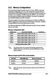
... x1 DDRC2 SDRAM 128MB, 256MB, 512MB, 1GB, 2GB x1 Total System Memory (Max. 12GB) = The system chipset only supports PC2100/1600 registered ECC DIMMs. Make sure to pairs DDRB1/DDRB2 and DDRC1/DDRC2. ASUS PR-DLS533 motherboard user guide 2-9 The same rule applies to use only the specified DIMM... types for stable system operation. As a rule, this configuration requires that the memory frequency matches the CPU FSB (Front Side Bus).
... x1 DDRC2 SDRAM 128MB, 256MB, 512MB, 1GB, 2GB x1 Total System Memory (Max. 12GB) = The system chipset only supports PC2100/1600 registered ECC DIMMs. Make sure to pairs DDRB1/DDRB2 and DDRC1/DDRC2. ASUS PR-DLS533 motherboard user guide 2-9 The same rule applies to use only the specified DIMM... types for stable system operation. As a rule, this configuration requires that the memory frequency matches the CPU FSB (Front Side Bus).

Manual PDF file for PR-DLS533
Page 43
PR-DLS533 PR-DLS533 SCSI Setting SCSI_EN Enable (Default) Disable 5. Short the solder pads for about 5 seconds. 4. You can clear the CMOS memory of date, time, and system setup parameters by the onboard button cell battery. Remove the battery. 3. Re-install the battery. ...down the key during the boot process and enter BIOS setup to Clear CMOS CR2032 3V Lithium Cell CMOS Power R452 ASUS ASIC with Hardware Monitor PR-DLS533 PR-DLS533 Clear RTC RAM ASUS PR-DLS533 motherboard user guide 2-17 Short solder points to re-enter data. Plug the power cord and turn ON the ...
PR-DLS533 PR-DLS533 SCSI Setting SCSI_EN Enable (Default) Disable 5. Short the solder pads for about 5 seconds. 4. You can clear the CMOS memory of date, time, and system setup parameters by the onboard button cell battery. Remove the battery. 3. Re-install the battery. ...down the key during the boot process and enter BIOS setup to Clear CMOS CR2032 3V Lithium Cell CMOS Power R452 ASUS ASIC with Hardware Monitor PR-DLS533 PR-DLS533 Clear RTC RAM ASUS PR-DLS533 motherboard user guide 2-17 Short solder points to re-enter data. Plug the power cord and turn ON the ...
Manual PDF file for PR-DLS533
Page 49
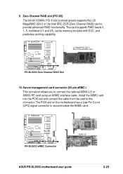
...) signal connector to this connector. Server management card connector (50-pin eRMC ) This connector allows you to provide advanced RAID functionality. ASMC-HE PR-DLS533 PR-DLS533 eRMC Connector ASMC-LE ASUS PR-DLS533 motherboard user guide 2-23 Zero Channel RAID slot (PCI-X5) The 64-bit/100MHz PCI-X slot (colored green) supports the LSI MegaRAID 320... RAID) card to connect the optional ASMC-LE or ASMC-HE card using an ASMC interface cable. The card supports RAID levels 0, 1, 5, multilevel 0/1 and 0/5, cache memory modules with ECC, and predictive caching capability. 9.
...) signal connector to this connector. Server management card connector (50-pin eRMC ) This connector allows you to provide advanced RAID functionality. ASMC-HE PR-DLS533 PR-DLS533 eRMC Connector ASMC-LE ASUS PR-DLS533 motherboard user guide 2-23 Zero Channel RAID slot (PCI-X5) The 64-bit/100MHz PCI-X slot (colored green) supports the LSI MegaRAID 320... RAID) card to connect the optional ASMC-LE or ASMC-HE card using an ASMC interface cable. The card supports RAID levels 0, 1, 5, multilevel 0/1 and 0/5, cache memory modules with ECC, and predictive caching capability. 9.
Manual PDF file for PR-DLS533
Page 57
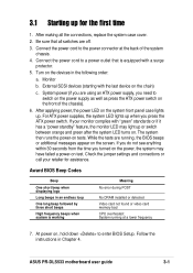
... retailer for the first time 1. ASUS PR-DLS533 motherboard user guide 3-1 3.1 Starting up . After applying power, the power LED on the chain) c. At power on test. Be sure that is working Meaning No error during POST No DRAM installed or detected Video card not found or video card memory bad CPU overheated; If you...
... retailer for the first time 1. ASUS PR-DLS533 motherboard user guide 3-1 3.1 Starting up . After applying power, the power LED on the chain) c. At power on test. Be sure that is working Meaning No error during POST No DRAM installed or detected Video card not found or video card memory bad CPU overheated; If you...
Manual PDF file for PR-DLS533
Page 61
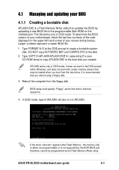
... the motherboard. If the word "unknown" appears after Flash Memory:, the memory chip is either not programmable or is not supported by the ACPI BIOS and therefore, cannot be loaded when you boot from the floppy disk. Larger numbers represent a newer BIOS file. 1. ASUS PR-DLS533 motherboard user guide 4-1 It does not work in DOS...
... the motherboard. If the word "unknown" appears after Flash Memory:, the memory chip is either not programmable or is not supported by the ACPI BIOS and therefore, cannot be loaded when you boot from the floppy disk. Larger numbers represent a newer BIOS file. 1. ASUS PR-DLS533 motherboard user guide 4-1 It does not work in DOS...
Manual PDF file for PR-DLS533
Page 64
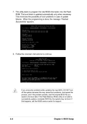
... encounter problems while updating the new BIOS, DO NOT turn off the system because this happens, call the ASUS service center for support. 4-4 Chapter 4: BIOS Setup If this may not boot. If the Flash Memory Writer utility is not able to successfully update a complete BIOS file, the system may cause boot problems...
... encounter problems while updating the new BIOS, DO NOT turn off the system because this happens, call the ASUS service center for support. 4-4 Chapter 4: BIOS Setup If this may not boot. If the Flash Memory Writer utility is not able to successfully update a complete BIOS file, the system may cause boot problems...
Manual PDF file for PR-DLS533
Page 69
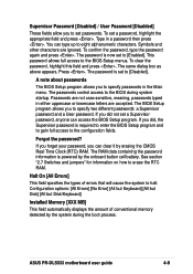
... and jumpers" for information on how to the BIOS Setup menus. Halt On [All Errors] This field specifies the types of conventional memory detected by erasing the CMOS Real Time Clock (RTC) RAM. You can access the BIOS Setup program. This password allows full access ...you did , the Supervisor password is now set to [Disabled]. If you forget your password, you to specify passwords in the Main menu. ASUS PR-DLS533 motherboard user guide 4-9 To set passwords. Symbols and other characters are accepted. Supervisor Password [Disabled] / User Password [Disabled] These fields allow...
... and jumpers" for information on how to the BIOS Setup menus. Halt On [All Errors] This field specifies the types of conventional memory detected by erasing the CMOS Real Time Clock (RTC) RAM. You can access the BIOS Setup program. This password allows full access ...you did , the Supervisor password is now set to [Disabled]. If you forget your password, you to specify passwords in the Main menu. ASUS PR-DLS533 motherboard user guide 4-9 To set passwords. Symbols and other characters are accepted. Supervisor Password [Disabled] / User Password [Disabled] These fields allow...
Manual PDF file for PR-DLS533
Page 76
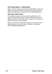
Otherwise, leave to [Enabled]. If not detected, the USB controller legacy mode is enabled. OS/2 Onboard Memory > 64M [Disabled] When using a USB device. If detected, the USB controller legacy mode is disabled. When you are using OS/2 operating systems with installed DRAM ...
Otherwise, leave to [Enabled]. If not detected, the USB controller legacy mode is enabled. OS/2 Onboard Memory > 64M [Disabled] When using a USB device. If detected, the USB controller legacy mode is disabled. When you are using OS/2 operating systems with installed DRAM ...
Manual PDF file for PR-DLS533
Page 77
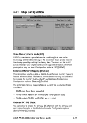
...memory mapping feature. Configuration options: [Both] [Primary] [Disabled] ASUS PR-DLS533 motherboard user guide 4-17 Configuration options: [UC] [USWC] Enhanced Memory Mapping [Enabled] This item allows you to UC (uncacheable) if your system may not boot. Configuration options: [Disabled] [Enabled] The enhanced memory...uncacheable, speculative write combining) is a new cache technology for the video memory of the processor. otherwise your display card cannot support this feature permits better memory bus utilization to enable the primary IDE channel, both the primary and ...
...memory mapping feature. Configuration options: [Both] [Primary] [Disabled] ASUS PR-DLS533 motherboard user guide 4-17 Configuration options: [UC] [USWC] Enhanced Memory Mapping [Enabled] This item allows you to UC (uncacheable) if your system may not boot. Configuration options: [Disabled] [Enabled] The enhanced memory...uncacheable, speculative write combining) is a new cache technology for the video memory of the processor. otherwise your display card cannot support this feature permits better memory bus utilization to enable the primary IDE channel, both the primary and ...
Manual PDF file for PR-DLS533
Page 90
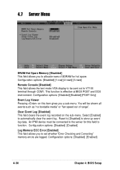
... clears the event log recorded on this field to function. Reset to [Disabled] to set whether "Error Checking and Correcting" memory errors are logged. Configuration options: [Disabled] [Enabled] Log Memory ECC Error [Enabled] This field allows you to store up event log data. Configuration options: [Disabled] [1 row] [2... clear the event log. This function is effective at BIOS POST and DOS environment. 4.7 Server Menu DRAM Hot Spare Memory [Disabled] This field allows you to allocate rows of range". Configuration options: [Disabled] [Enabled] 4-30 Chapter 4: BIOS Setup
... clears the event log recorded on this field to function. Reset to [Disabled] to set whether "Error Checking and Correcting" memory errors are logged. Configuration options: [Disabled] [Enabled] Log Memory ECC Error [Enabled] This field allows you to store up event log data. Configuration options: [Disabled] [1 row] [2... clear the event log. This function is effective at BIOS POST and DOS environment. 4.7 Server Menu DRAM Hot Spare Memory [Disabled] This field allows you to allocate rows of range". Configuration options: [Disabled] [Enabled] 4-30 Chapter 4: BIOS Setup