
Manual PDF file for PR-DLS533
Page 4
... 2.6.1 Installing an expansion card 2-11 2.6.2 Configuring an expansion card 2-11 2.6.3 PCI slots 2-13 2.7 Switches and jumpers 2-14 2.7.1 Switches 2-14 2.7.2 Jumpers 2-15 2.8 Connectors 2-18 Chapter 3: Powering up 3.1 Starting up for the first time 3-1 3.2 Powering off the computer 3-2 Chapter 4: ...
... 2.6.1 Installing an expansion card 2-11 2.6.2 Configuring an expansion card 2-11 2.6.3 PCI slots 2-13 2.7 Switches and jumpers 2-14 2.7.1 Switches 2-14 2.7.2 Jumpers 2-15 2.8 Connectors 2-18 Chapter 3: Powering up 3.1 Starting up for the first time 3-1 3.2 Powering off the computer 3-2 Chapter 4: ...

Manual PDF file for PR-DLS533
Page 7
..., contact a qualified service technician or your retailer. Do not place the product in your power supply is broken, do not try to or from connectors, slots, sockets and circuitry. • Avoid dust, humidity, and temperature extremes. If you encounter technical problems with the package. • Before using an adpater or extension...
..., contact a qualified service technician or your retailer. Do not place the product in your power supply is broken, do not try to or from connectors, slots, sockets and circuitry. • Avoid dust, humidity, and temperature extremes. If you encounter technical problems with the package. • Before using an adpater or extension...
Manual PDF file for PR-DLS533
Page 11
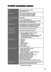
PR-DLS533 specifications summary CPU Chipsets Front Side Bus (FSB) Memory Onboard LAN Onboard SCSI Onboard VGA Expansion slots Rear panel I/O Internal connectors BIOS features Support for Intel® Xeon™ processor On-die 512KB L2 cache RCC Grand Champion LE Server (GCLE) RCC ...
PR-DLS533 specifications summary CPU Chipsets Front Side Bus (FSB) Memory Onboard LAN Onboard SCSI Onboard VGA Expansion slots Rear panel I/O Internal connectors BIOS features Support for Intel® Xeon™ processor On-die 512KB L2 cache RCC Grand Champion LE Server (GCLE) RCC ...

Manual PDF file for PR-DLS533
Page 16
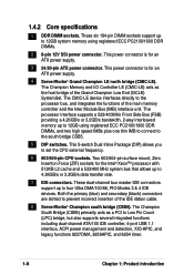
...memory bus doubles the speed of the PC133 SDRAM to offer a significant increase in performance. Advanced 64-bit PCI-X slots The 64-bit/133MHz PCI-X slots onboard maximizes I /O and server management cards. See page 2-10. ATA/100 IDE support The dual-channel bus master... intelligent I /O bandwidth for the latest 3D graphics, multimedia, and Internet applications. 1.3 Special features 1.3.1 Product highlights Latest processor technology The PR-DLS533 motherboard supports the Intel® Xeon processor via dual 603/604-pin surface mount ZIF sockets. Dual-channel Ultra320 SCSI The LSI® ...
...memory bus doubles the speed of the PC133 SDRAM to offer a significant increase in performance. Advanced 64-bit PCI-X slots The 64-bit/133MHz PCI-X slots onboard maximizes I /O and server management cards. See page 2-10. ATA/100 IDE support The dual-channel bus master... intelligent I /O bandwidth for the latest 3D graphics, multimedia, and Internet applications. 1.3 Special features 1.3.1 Product highlights Latest processor technology The PR-DLS533 motherboard supports the Intel® Xeon processor via dual 603/604-pin surface mount ZIF sockets. Dual-channel Ultra320 SCSI The LSI® ...

Manual PDF file for PR-DLS533
Page 20
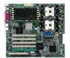
...2 for the specifications of the motherboard specifications will also help you install the PR-DLS533 motherboard, familiarize yourself with its components. 1.4.1 Major components The following are the major components of the PR-DLS533 motherboard as pointed out in the picture on the components. 1-6 Chapter 1:...component. ServerWorks® Grand Champion LE North Bridge (CMIC-LE) 5. IDE connectors 8. ASUS ASIC 13. ServerWorks® 64-bit I /O controller 19. PCI-X slots (PCI-X1 to PCI-X5) PCI slot (PCI6) 17. Intel® 82540EM 32-bit PCI Gigabit Ethernet controller (or Intel&#...
...2 for the specifications of the motherboard specifications will also help you install the PR-DLS533 motherboard, familiarize yourself with its components. 1.4.1 Major components The following are the major components of the PR-DLS533 motherboard as pointed out in the picture on the components. 1-6 Chapter 1:...component. ServerWorks® Grand Champion LE North Bridge (CMIC-LE) 5. IDE connectors 8. ASUS ASIC 13. ServerWorks® 64-bit I /O controller 19. PCI-X slots (PCI-X1 to PCI-X5) PCI slot (PCI6) 17. Intel® 82540EM 32-bit PCI Gigabit Ethernet controller (or Intel&#...
Manual PDF file for PR-DLS533
Page 22
Both the primary (blue) and secondary (black) connectors are slotted to the south bridge CSB5. 5 DIP switches. The processor interface supports a 533/400MHz Front Side Bus (FSB) providing a 4.26GB/s or 3.2GB/s bandwidth, 2-way interleaved memory ...
Both the primary (blue) and secondary (black) connectors are slotted to the south bridge CSB5. 5 DIP switches. The processor interface supports a 533/400MHz Front Side Bus (FSB) providing a 4.26GB/s or 3.2GB/s bandwidth, 2-way interleaved memory ...
Manual PDF file for PR-DLS533
Page 23
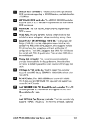
... connector accommodates the provided ribbon cable for 1280x1024 and true color resolutions. 16 PCI-X/PCI slots. 9 Ultra320 SCSI connectors. This 4Mb flash ROM contains the programmable BIOS program. 12 ASUS ASIC. The CIOB-X2 supports dual 64-bit PCI-X I/O buses that include hardware and...one 64-bit/100MHz PCI-X slots, and a 32-bit/33MHz PCI expansion slot support bus master PCI-X/PCI cards. 17 Intel® 82540EM 32-bit PCI Gigabit Ethernet controller. This LAN controller fully supports 10BASE-T/100BASE-TX networking protocols. (optional) ASUS PR-DLS533 motherboard user guide 1-9 These...
... connector accommodates the provided ribbon cable for 1280x1024 and true color resolutions. 16 PCI-X/PCI slots. 9 Ultra320 SCSI connectors. This 4Mb flash ROM contains the programmable BIOS program. 12 ASUS ASIC. The CIOB-X2 supports dual 64-bit PCI-X I/O buses that include hardware and...one 64-bit/100MHz PCI-X slots, and a 32-bit/33MHz PCI expansion slot support bus master PCI-X/PCI cards. 17 Intel® 82540EM 32-bit PCI Gigabit Ethernet controller. This LAN controller fully supports 10BASE-T/100BASE-TX networking protocols. (optional) ASUS PR-DLS533 motherboard user guide 1-9 These...
Manual PDF file for PR-DLS533
Page 26
Chapter summary 2.1 Motherboard installation 2-1 2.2 Motherboard layout 2-2 2.3 Before you proceed 2-3 2.4 Central Processing Unit (CPU 2-3 2.5 System memory 2-8 2.6 Expansion slots 2-11 2.7 Switches and jumpers 2-14 2.8 Connectors 2-18 ASUS PR-DLS533 motherboard
Chapter summary 2.1 Motherboard installation 2-1 2.2 Motherboard layout 2-2 2.3 Before you proceed 2-3 2.4 Central Processing Unit (CPU 2-3 2.5 System memory 2-8 2.6 Expansion slots 2-11 2.7 Switches and jumpers 2-14 2.8 Connectors 2-18 ASUS PR-DLS533 motherboard

Manual PDF file for PR-DLS533
Page 37
... install an expansion card. 1. Before installing the expansion card, read the documentation that they support. Align the card connector with the slot and press firmly until the card is already installed in a chassis). 3. See Chapter 4 for later use . Keep the screw for information ... for the card. 2. Turn on the next page. 3. Secure the card to install expansion cards. ASUS PR-DLS533 motherboard user guide 2-11 Refer to use . 4. The following subsections describe the slots and the expansion cards that came with the screw you intend to the tables on the system and change...
... install an expansion card. 1. Before installing the expansion card, read the documentation that they support. Align the card connector with the slot and press firmly until the card is already installed in a chassis). 3. See Chapter 4 for later use . Keep the screw for information ... for the card. 2. Turn on the next page. 3. Secure the card to install expansion cards. ASUS PR-DLS533 motherboard user guide 2-11 Refer to use . 4. The following subsections describe the slots and the expansion cards that came with the screw you intend to the tables on the system and change...

Manual PDF file for PR-DLS533
Page 38
... two PCI groups, making the system unstable and the card inoperable. 2-12 Chapter 2: Hardware information When using PCI cards on shared slots, ensure that the drivers support "Share IRQ" or that the cards do not need IRQ assignments. PCI INTC 13 16 19 22... Primary IDE Channel 15* 10 Secondary IDE Channel * These IRQs are usually available for this motherboard PCI INTA PCI slot 1 1 PCI slot 2 4 PCI slot 3 5 PCI slot 4 8 PCI slot 5 9 PCI slot 6 10 Onboard 82551QM controller 2 Onboard 82544GC controller 3 Onboard SCSI controller 6 Onboard VGA controller 30 PCI INTB 12...
... two PCI groups, making the system unstable and the card inoperable. 2-12 Chapter 2: Hardware information When using PCI cards on shared slots, ensure that the drivers support "Share IRQ" or that the cards do not need IRQ assignments. PCI INTC 13 16 19 22... Primary IDE Channel 15* 10 Secondary IDE Channel * These IRQs are usually available for this motherboard PCI INTA PCI slot 1 1 PCI slot 2 4 PCI slot 3 5 PCI slot 4 8 PCI slot 5 9 PCI slot 6 10 Onboard 82551QM controller 2 Onboard 82544GC controller 3 Onboard SCSI controller 6 Onboard VGA controller 30 PCI INTB 12...
Manual PDF file for PR-DLS533
Page 39
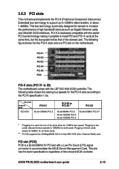
... 64-bit/133MHz PCI-X 64-bit/100MHz PCI-X** * Plugging in two cards reduces the bus speeds to accommodate the ASUS Server Management Card. 2.6.3 PCI slots This motherboard implements the PCI-X (Peripheral Component Interconnect Extended) bus technology to support up to X5) The motherboard comes ... for both cards. Plugging in three cards allows for 66MHz for 133MHz bus speed. ASUS PR-DLS533 motherboard user guide 2-13 PCI slot (PCI6) PCI6 is primarily designed for the PCI-X slots according to increase the performance of the slowest card. The following table shows the varying...
... 64-bit/133MHz PCI-X 64-bit/100MHz PCI-X** * Plugging in two cards reduces the bus speeds to accommodate the ASUS Server Management Card. 2.6.3 PCI slots This motherboard implements the PCI-X (Peripheral Component Interconnect Extended) bus technology to support up to X5) The motherboard comes ... for both cards. Plugging in three cards allows for 66MHz for 133MHz bus speed. ASUS PR-DLS533 motherboard user guide 2-13 PCI slot (PCI6) PCI6 is primarily designed for the PCI-X slots according to increase the performance of the slowest card. The following table shows the varying...

Manual PDF file for PR-DLS533
Page 44
...using ribbon cables with pin 5 plug). Pin 1 is removed to Pin 1 on the motherboard. PR-DLS533 Floppy Disk Drive Connector 2. FLOPPY PIN 1 NOTE: Orient the red markings on PR-DLS533 the floppy ribbon cable to the power connector on hard drives and CD-ROM drives, but may be..., connect the other end to the floppy drive. (Pin 5 is usually on floppy disk drives. 1. PIN 1 PR-DLS533 PR-DLS533 Serial COM2 Connector 2-18 Chapter 2: Hardware information Connect the bracket cable to this connector then install the bracket into a slot opening at the back of the system chassis.
...using ribbon cables with pin 5 plug). Pin 1 is removed to Pin 1 on the motherboard. PR-DLS533 Floppy Disk Drive Connector 2. FLOPPY PIN 1 NOTE: Orient the red markings on PR-DLS533 the floppy ribbon cable to the power connector on hard drives and CD-ROM drives, but may be..., connect the other end to the floppy drive. (Pin 5 is usually on floppy disk drives. 1. PIN 1 PR-DLS533 PR-DLS533 Serial COM2 Connector 2-18 Chapter 2: Hardware information Connect the bracket cable to this connector then install the bracket into a slot opening at the back of the system chassis.
Manual PDF file for PR-DLS533
Page 49
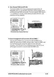
...the ASMC card. The PCI6 slot on the motherboard has a Low Pin Count (LPC) signal connector to connect the optional ASMC-LE or ASMC-HE card using an ASMC interface cable. ASMC-HE PR-DLS533 PR-DLS533 eRMC Connector ASMC-LE ASUS PR-DLS533 motherboard user guide 2-23 The... card supports RAID levels 0, 1, 5, multilevel 0/1 and 0/5, cache memory modules with ECC, and predictive caching capability. Install the ASMC card into the PCI6 slot and connect the cable from...
...the ASMC card. The PCI6 slot on the motherboard has a Low Pin Count (LPC) signal connector to connect the optional ASMC-LE or ASMC-HE card using an ASMC interface cable. ASMC-HE PR-DLS533 PR-DLS533 eRMC Connector ASMC-LE ASUS PR-DLS533 motherboard user guide 2-23 The... card supports RAID levels 0, 1, 5, multilevel 0/1 and 0/5, cache memory modules with ECC, and predictive caching capability. Install the ASMC card into the PCI6 slot and connect the cable from...

Manual PDF file for PR-DLS533
Page 80
... to reserve the bus number for best performance vs. Configuration options: [Disabled] [Enabled] PCI Latency Timer [32] Leave on default setting for the PCI slots. Configuration options: [Auto] [NA] [3] [4] [5] [7] [9] [10] [11] [12] [14] [15] PCI/VGA Palette Snoop [Disabled] Some ...non-standard VGA cards, like graphics accelerators or MPEG video cards, may not show colors properly. 4.4.3 PCI Configuration Slot 1, Slot 2, Slot 3, Slot 4, Slot 5, Slot 6 IRQ [Auto] These fields set how IRQ use is [Auto], which utilizes auto-routing to determine IRQ use. The default ...
... to reserve the bus number for best performance vs. Configuration options: [Disabled] [Enabled] PCI Latency Timer [32] Leave on default setting for the PCI slots. Configuration options: [Auto] [NA] [3] [4] [5] [7] [9] [10] [11] [12] [14] [15] PCI/VGA Palette Snoop [Disabled] Some ...non-standard VGA cards, like graphics accelerators or MPEG video cards, may not show colors properly. 4.4.3 PCI Configuration Slot 1, Slot 2, Slot 3, Slot 4, Slot 5, Slot 6 IRQ [Auto] These fields set how IRQ use is [Auto], which utilizes auto-routing to determine IRQ use. The default ...

Manual PDF file for PR-DLS533
Page 88
... BCV device is selected, interrupts may be reassigned by the OS. If you installed a nonPnP OS or if you want to configure the PCI bus slots instead of using the BIOS. It also holds the complete record of interrupt settings, keep the default setting [No]. The BCV devices present in the...
... BCV device is selected, interrupts may be reassigned by the OS. If you installed a nonPnP OS or if you want to configure the PCI bus slots instead of using the BIOS. It also holds the complete record of interrupt settings, keep the default setting [No]. The BCV devices present in the...

Manual PDF file for PR-DLS533
Page 89
.... Configuration options: [High] [Normal] [Low] [Skip] ASUS PR-DLS533 motherboard user guide 4-29 Configuration options: [Disabled] [Enabled] Boot Up Floppy Seek [Enabled] When enabled, the BIOS will seek the floppy disk drive to enable or disable the MultiProcessor Specification 1.4 support. Configuration options: [Disabled] [Enabled] 4.6.1 Boot Configuration Init Slot 1, 2, 3, 4, 5, 6 IRQ [Normal] This field allows you...
.... Configuration options: [High] [Normal] [Low] [Skip] ASUS PR-DLS533 motherboard user guide 4-29 Configuration options: [Disabled] [Enabled] Boot Up Floppy Seek [Enabled] When enabled, the BIOS will seek the floppy disk drive to enable or disable the MultiProcessor Specification 1.4 support. Configuration options: [Disabled] [Enabled] 4.6.1 Boot Configuration Init Slot 1, 2, 3, 4, 5, 6 IRQ [Normal] This field allows you...

Manual PDF file for PR-DLS533
Page 126
...loaded for later use. 6. Modify any option values as needed. 4. Load a separate instance of the installation screen. Make sure to write these slot numbers down in the system. 5. A more detailed description is loaded once per load instance. When prompted for every LSI Logic controller SCSI channel ...5: Driver installation When asked to each load line in the STARTUP.NCF, specifying the slot numbers written down for each option appears in the section titled Command Line Options. Add the statement SLOT= to edit the STARTUP.NCF file, make sure the LSIMPTNW.HAM is given in ...
...loaded for later use. 6. Modify any option values as needed. 4. Load a separate instance of the installation screen. Make sure to write these slot numbers down in the system. 5. A more detailed description is loaded once per load instance. When prompted for every LSI Logic controller SCSI channel ...5: Driver installation When asked to each load line in the STARTUP.NCF, specifying the slot numbers written down for each option appears in the section titled Command Line Options. Add the statement SLOT= to edit the STARTUP.NCF file, make sure the LSIMPTNW.HAM is given in ...

Manual PDF file for PR-DLS533
Page 129
... driver. When finished configuring the driver, select Save parameters and load driver to select it. 8. 7. Press to continue. 10. ASUS PR-DLS533 motherboard user guide 5-35 If you have multiple adapters, enter the slot number for the adapter you want to the server console prompt. 5.5.3 ATI® Rage XL Display Driver Installation You can...
... driver. When finished configuring the driver, select Save parameters and load driver to select it. 8. 7. Press to continue. 10. ASUS PR-DLS533 motherboard user guide 5-35 If you have multiple adapters, enter the slot number for the adapter you want to the server console prompt. 5.5.3 ATI® Rage XL Display Driver Installation You can...