
User Guide
Page 2
...LIABILITY FOR ANY ERRORS OR INACCURACIES THAT MAY APPEAR IN THIS MANUAL, INCLUDING THE PRODUCTS AND SOFTWARE DESCRIBED IN IT. IN NO EVENT SHALL ASUS, ITS DIRECTORS, OFFICERS, EMPLOYEES OR AGENTS BE LIABLE FOR ANY INDIRECT, SPECIAL, INCIDENTAL, OR CONSEQUENTIAL DAMAGES (INCLUDING DAMAGES FOR LOSS OF ... INFORMATION CONTAINED IN THIS MANUAL ARE FURNISHED FOR INFORMATIONAL USE ONLY, AND ARE SUBJECT TO CHANGE AT ANY TIME WITHOUT NOTICE, AND SHOULD NOT BE CONSTRUED AS A COMMITMENT BY ASUS. No part of their respective companies, and are used only for backup purposes, without intent to the owners...
...LIABILITY FOR ANY ERRORS OR INACCURACIES THAT MAY APPEAR IN THIS MANUAL, INCLUDING THE PRODUCTS AND SOFTWARE DESCRIBED IN IT. IN NO EVENT SHALL ASUS, ITS DIRECTORS, OFFICERS, EMPLOYEES OR AGENTS BE LIABLE FOR ANY INDIRECT, SPECIAL, INCIDENTAL, OR CONSEQUENTIAL DAMAGES (INCLUDING DAMAGES FOR LOSS OF ... INFORMATION CONTAINED IN THIS MANUAL ARE FURNISHED FOR INFORMATIONAL USE ONLY, AND ARE SUBJECT TO CHANGE AT ANY TIME WITHOUT NOTICE, AND SHOULD NOT BE CONSTRUED AS A COMMITMENT BY ASUS. No part of their respective companies, and are used only for backup purposes, without intent to the owners...

User Guide
Page 4
... 2-30 2.8.2 Internal connectors 2-31 Chapter 3: Powering Up 3-1 3.1 Starting up for the first time 3-3 3.2 Powering off the computer 3-4 3.2.1 Using the OS shut down function 3-4 3.2.2 Using the dual function power switch 3-4 Chapter 4: BIOS setup 4-1 4.1 Managing and updating your BIOS 4-3 4.1.1 ASUS CrashFree BIOS 3 utility 4-3 4.1.2 ASUS Easy Flash Utility 4-4 4.1.3 BUPDATER utility 4-5 4.2 BIOS setup program 4-7 4.2.1 BIOS menu screen...
... 2-30 2.8.2 Internal connectors 2-31 Chapter 3: Powering Up 3-1 3.1 Starting up for the first time 3-3 3.2 Powering off the computer 3-4 3.2.1 Using the OS shut down function 3-4 3.2.2 Using the dual function power switch 3-4 Chapter 4: BIOS setup 4-1 4.1 Managing and updating your BIOS 4-3 4.1.1 ASUS CrashFree BIOS 3 utility 4-3 4.1.2 ASUS Easy Flash Utility 4-4 4.1.3 BUPDATER utility 4-5 4.2 BIOS setup program 4-7 4.2.1 BIOS menu screen...

User Guide
Page 19
... 2.0 technology The motherboard implements the Universal Serial Bus (USB) 2.0 specification that provides twice the performance and speed of PCIe 2.0. ASUS P9D-M Series 1-5 The onboard Intel® I210AT Gigabit LAN controllers use the PCI Express interface and could achieve network throughput close to... (RPM) is monitored for your networking needs. Serial ATA allows thinner, more flexible cables with up to 5Gbps, faster charging time for critical components. The Serial ATA II specification provides twice the bandwidth of new features, including Native Command Queuing (NCQ), Power...
... 2.0 technology The motherboard implements the Universal Serial Bus (USB) 2.0 specification that provides twice the performance and speed of PCIe 2.0. ASUS P9D-M Series 1-5 The onboard Intel® I210AT Gigabit LAN controllers use the PCI Express interface and could achieve network throughput close to... (RPM) is monitored for your networking needs. Serial ATA allows thinner, more flexible cables with up to 5Gbps, faster charging time for critical components. The Serial ATA II specification provides twice the bandwidth of new features, including Native Command Queuing (NCQ), Power...

User Guide
Page 33
... and heatsink assembly. Push down two fasteners at a time in a pushpin design and requires no tools to install while the special heatsink assembly requires a Phillips screwdriver to tighten or loosen screws. • Use an LGA1150-compatible CPU heatsink and CPU fan assembly only. ASUS P9D-M Series 2-13 2.3.2 Installing the CPU heatsink The Intel...
... and heatsink assembly. Push down two fasteners at a time in a pushpin design and requires no tools to install while the special heatsink assembly requires a Phillips screwdriver to tighten or loosen screws. • Use an LGA1150-compatible CPU heatsink and CPU fan assembly only. ASUS P9D-M Series 2-13 2.3.2 Installing the CPU heatsink The Intel...

User Guide
Page 34
... the heatsink and fan assembly from the motherboard. 3. Disconnect the CPU fan cable from the motherboard. 2-14 Chapter 2: Hardware information A B A A B B A 4. Pull up two fasteners at a time in a diagonal sequence to connect the CPU fan connector! Carefully remove the heatsink and fan assembly from the connector on the motherboard labeled CPU_FAN1. Hardware...
... the heatsink and fan assembly from the motherboard. 3. Disconnect the CPU fan cable from the motherboard. 2-14 Chapter 2: Hardware information A B A A B B A 4. Pull up two fasteners at a time in a diagonal sequence to connect the CPU fan connector! Carefully remove the heatsink and fan assembly from the connector on the motherboard labeled CPU_FAN1. Hardware...

User Guide
Page 39
... -- 8 3 System CMOS/Real Time Clock 9* 4 ACPI Mode when used 10* 5 IRQ Holder for PCI Steering 11* 6 IRQ Holder for PCI Steering 12* 7 PS/2 Compatible Mouse Port 13 8 Numeric Data Processor 14* 9 Primary IDE Channel 15* 10 Secondary IDE Channel * These IRQs are usually available for ISA or PCI devices. ASUS P9D-M Series 2-19...
... -- 8 3 System CMOS/Real Time Clock 9* 4 ACPI Mode when used 10* 5 IRQ Holder for PCI Steering 11* 6 IRQ Holder for PCI Steering 12* 7 PS/2 Compatible Mouse Port 13 8 Numeric Data Processor 14* 9 Primary IDE Channel 15* 10 Secondary IDE Channel * These IRQs are usually available for ISA or PCI devices. ASUS P9D-M Series 2-19...

User Guide
Page 46
... and enter BIOS setup to pins 1-2. 3. Clear RTC RAM (3-pin CLRTC1) This jumper allows you to pins 2-3. You can clear the CMOS memory of date, time, and system setup parameters by erasing the CMOS RTC RAM data. Except when clearing the RTC RAM, never remove the cap on pins 2-3 for about... 5-10 seconds, then move the jumper again to clear the CMOS RTC RAM data. Move the jumper cap from pins 1-2 (default) to clear the Real Time Clock (RTC) RAM in CMOS, which include system setup information such as system passwords. Turn OFF the computer and unplug the power cord. 2. If the...
... and enter BIOS setup to pins 1-2. 3. Clear RTC RAM (3-pin CLRTC1) This jumper allows you to pins 2-3. You can clear the CMOS memory of date, time, and system setup parameters by erasing the CMOS RTC RAM data. Except when clearing the RTC RAM, never remove the cap on pins 2-3 for about... 5-10 seconds, then move the jumper again to clear the CMOS RTC RAM data. Move the jumper cap from pins 1-2 (default) to clear the Real Time Clock (RTC) RAM in CMOS, which include system setup information such as system passwords. Turn OFF the computer and unplug the power cord. 2. If the...

User Guide
Page 54
... or rear panel ports. Thermal sensor cable connectors (3-pin TR1) This connector allows you to connect a Thermal sensor cable that you to 5Gbps, faster charging time for temperature monitoring. Connect the Thermal sensor cable to the connector and place its probe to check the temperature. 2-34 Chapter 2: Hardware information USB 3.0 connector... USB3_34)* These connectors allow you want to the device that is used for USB-chargeable devices, optimized power efficiency, and backward compatibility with USB 2.0. *For P9D-M motherboard only 5. 4.
... or rear panel ports. Thermal sensor cable connectors (3-pin TR1) This connector allows you to connect a Thermal sensor cable that you to 5Gbps, faster charging time for temperature monitoring. Connect the Thermal sensor cable to the connector and place its probe to check the temperature. 2-34 Chapter 2: Hardware information USB 3.0 connector... USB3_34)* These connectors allow you want to the device that is used for USB-chargeable devices, optimized power efficiency, and backward compatibility with USB 2.0. *For P9D-M motherboard only 5. 4.

User Guide
Page 62
Chapter summary 3 This chapter describes the power up sequence, and ways of shutting down the system.This chapter contains the following sections: 3.1 Starting up for the first time 3-3 3.2 Powering off the computer 3-4 ASUS P9D-M Series
Chapter summary 3 This chapter describes the power up sequence, and ways of shutting down the system.This chapter contains the following sections: 3.1 Starting up for the first time 3-3 3.2 Powering off the computer 3-4 ASUS P9D-M Series

User Guide
Page 63
...screen. External storage devices (starting with a surge protector. 5. If you do not see anything within 30 seconds from the time you press the ATX power button. Follow the instructions in the following order: a. 3.1 Starting up . Connect the power cord... up for assistance. 7. After applying power, the system power LED on test. If your retailer for the first time 1. Connect the power cord to a power outlet that all the connections, replace the system case cover. 2. Check... key to the power connector at the back of the system chassis. 4. ASUS P9D-M Series 3-3
...screen. External storage devices (starting with a surge protector. 5. If you do not see anything within 30 seconds from the time you press the ATX power button. Follow the instructions in the following order: a. 3.1 Starting up . Connect the power cord... up for assistance. 7. After applying power, the system power LED on test. If your retailer for the first time 1. Connect the power cord to a power outlet that all the connections, replace the system case cover. 2. Check... key to the power connector at the back of the system chassis. 4. ASUS P9D-M Series 3-3

User Guide
Page 72
System Date System Time [Mon 01/06/2013] [15:07:28] →←: Select Screen ↑↓: Select Item Enter: Select Item +/-: Change Opt. Main Advanced Event Logs Boot ...
System Date System Time [Mon 01/06/2013] [15:07:28] →←: Select Screen ↑↓: Select Item Enter: Select Item +/-: Change Opt. Main Advanced Event Logs Boot ...

User Guide
Page 74
... Compliancy BIOS Version Build Date American Megatrends 4.6.5.4 UEFI 2.3.1; Where: Day = Day of the basic system information, and allows you to set the system date and time. Where: hh = hour (numeric value) mm = minutes (numeric value) ss = seconds (numeric value) 4-10 Chapter 4: BIOS setup PI 1.2 0212 x64 03/26/2013 Set ..., Inc. The Main menu provides you an overview of the week mm = month (numeric value) dd = day (numeric value) yyyy = year (numeric value) 4.3.2 System Time Allows you to [Day mm/dd/yyyy]. 4.3 Main menu When you to set the system date to set the system...
... Compliancy BIOS Version Build Date American Megatrends 4.6.5.4 UEFI 2.3.1; Where: Day = Day of the basic system information, and allows you to set the system date and time. Where: hh = hour (numeric value) mm = minutes (numeric value) ss = seconds (numeric value) 4-10 Chapter 4: BIOS setup PI 1.2 0212 x64 03/26/2013 Set ..., Inc. The Main menu provides you an overview of the week mm = month (numeric value) dd = day (numeric value) yyyy = year (numeric value) 4.3.2 System Time Allows you to [Day mm/dd/yyyy]. 4.3 Main menu When you to set the system date to set the system...

User Guide
Page 83
... Not Present Not Present 4096 MB (DDR3) 9 9 9 24 Maximum Memory Frequency Selections in MHz. Configuration options: [Enabled] [Disabled] ASUS P9D-M Series 4-19 Configuration options: [1333] [1600] Memory Scrambler [Enabled] This allows you to enable or disable the Memory Scrambler support. Advanced... Memory Information Memory RC Version Memory Frequency Usage Memory DIMM_A1 DIMM_A2 DIMM_A3 DIMM_A4 CAS Latency (tCL) Minimum delay time CAS to RAS (tRCDmin) Row Precharge (tRPmin) Active to set the memory frequency in MHz. Configuration options: [Enabled]...
... Not Present Not Present 4096 MB (DDR3) 9 9 9 24 Maximum Memory Frequency Selections in MHz. Configuration options: [Enabled] [Disabled] ASUS P9D-M Series 4-19 Configuration options: [1333] [1600] Memory Scrambler [Enabled] This allows you to enable or disable the Memory Scrambler support. Advanced... Memory Information Memory RC Version Memory Frequency Usage Memory DIMM_A1 DIMM_A2 DIMM_A3 DIMM_A4 CAS Latency (tCL) Minimum delay time CAS to RAS (tRCDmin) Row Precharge (tRPmin) Active to set the memory frequency in MHz. Configuration options: [Enabled]...

User Guide
Page 85
Copyright (C) 2012 American Megatrends, Inc. ASUS P9D-M Series 4-21 DISABLE option will keep USB devices available only for EFI applications. Advanced USB Configuration USB Devices 1 mouse,2 Hubs Legacy USB Support USB3.0 Support ... American Megatrends, Inc. Aptio Setup Utility - PCIE Slot Configuration Allows you to make changes on the configuration settings of the USB. USB hardware delays and time-outs: USB transfer time-out [20 sec] Device reset time-out [20 sec] Device power-up delay [Auto] The USB Devices item shows the auto-detected values.
Copyright (C) 2012 American Megatrends, Inc. ASUS P9D-M Series 4-21 DISABLE option will keep USB devices available only for EFI applications. Advanced USB Configuration USB Devices 1 mouse,2 Hubs Legacy USB Support USB3.0 Support ... American Megatrends, Inc. Aptio Setup Utility - PCIE Slot Configuration Allows you to make changes on the configuration settings of the USB. USB hardware delays and time-outs: USB transfer time-out [20 sec] Device reset time-out [20 sec] Device power-up delay [Auto] The USB Devices item shows the auto-detected values.

User Guide
Page 86
... a workaround for OSes without EHCI hand-off support. Configuration options: [Disabled] [Enabled] USB transfer time-out [20 sec] Allows you to select the USB transfer time-out value. Configuration options: [1 sec] [5 sec] [10 sec] [20 sec] Device reset time-out [20 sec] Allows you to select the USB device reset... value. Configuration options: [10 sec] [20 sec] [30 sec] [40 sec] Device power-up delay is set the maximum time the device will take before it properly reports itself to enable or disable the USB Mass Storage driver support. Configuration options: [Disabled] [...
... a workaround for OSes without EHCI hand-off support. Configuration options: [Disabled] [Enabled] USB transfer time-out [20 sec] Allows you to select the USB transfer time-out value. Configuration options: [1 sec] [5 sec] [10 sec] [20 sec] Device reset time-out [20 sec] Allows you to select the USB device reset... value. Configuration options: [10 sec] [20 sec] [30 sec] [40 sec] Device power-up delay is set the maximum time the device will take before it properly reports itself to enable or disable the USB Mass Storage driver support. Configuration options: [Disabled] [...

User Guide
Page 119
Wait until the process is displayed in the Volumes list. ASUS P9D-M Series 5-15 You can continue using Windows Disk Management before adding any data. This process could take a while depending on the number and size of the disks. The created RAID set is complete, then click OK when prompted. Confirm volume creation, then click Create Volume to partition your new volume using other applications during this time. 6. You still need to continue. If you wish to change the settings, go to Volume Properties. 5.
Wait until the process is displayed in the Volumes list. ASUS P9D-M Series 5-15 You can continue using Windows Disk Management before adding any data. This process could take a while depending on the number and size of the disks. The created RAID set is complete, then click OK when prompted. Confirm volume creation, then click Create Volume to partition your new volume using other applications during this time. 6. You still need to continue. If you wish to change the settings, go to Volume Properties. 5.

User Guide
Page 129
... to locate the file ASSETUP.EXE from the BIN folder. Contact The main screen of the Support DVD contains the following tabs: 1. ASUS P9D-M Series 6-7 Drivers 2. Visit the ASUS website (www.asus.com) for the latest updates on software and utilities. • The DVD is supported on the Windows® Server 2012 Operating System... automatically displays the main screen if Autorun is enabled in your computer, browse the contents of the support DVD are subject to change at any time without notice.
... to locate the file ASSETUP.EXE from the BIN folder. Contact The main screen of the Support DVD contains the following tabs: 1. ASUS P9D-M Series 6-7 Drivers 2. Visit the ASUS website (www.asus.com) for the latest updates on software and utilities. • The DVD is supported on the Windows® Server 2012 Operating System... automatically displays the main screen if Autorun is enabled in your computer, browse the contents of the support DVD are subject to change at any time without notice.
User Guide
Page 131
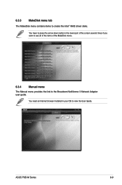
6.3.3 MakeDisk menu tab The MakeDisk menu contains items to view the User Guide. You need an Internet browser installed in the lower part of the screen several times if you want to see all of the items of the MakeDisk menu. 6.3.4 Manual menu The Manual menu provides the link to the Broadcom NetXtreme II Network Adapter user guide. ASUS P9D-M Series 6-9 You have to press the arrow down button in your OS to create the Intel® RAID driver disks.
6.3.3 MakeDisk menu tab The MakeDisk menu contains items to view the User Guide. You need an Internet browser installed in the lower part of the screen several times if you want to see all of the items of the MakeDisk menu. 6.3.4 Manual menu The Manual menu provides the link to the Broadcom NetXtreme II Network Adapter user guide. ASUS P9D-M Series 6-9 You have to press the arrow down button in your OS to create the Intel® RAID driver disks.

User Guide
Page 134
When finished, click Next. 10. The Windows Security window may appear more than once and you may have to click Install several times to complete the installation. 6-12 Chapter 6: Driver installation When prompted to restart the computer, select Yes, I want to restart this computer now then click Finish to continue with the installation. 9. 8. Click Install in the Windows Security window.
When finished, click Next. 10. The Windows Security window may appear more than once and you may have to click Install several times to complete the installation. 6-12 Chapter 6: Driver installation When prompted to restart the computer, select Yes, I want to restart this computer now then click Finish to continue with the installation. 9. 8. Click Install in the Windows Security window.