
User Manual
Page 3
Contents Notices...vi Safety information vii About this guide vii P8H61-M2 series specifications summary ix Chapter 1 Product introduction 1.1 Before you proceed 1-1 1.2 Motherboard overview 1-2 1.2.1 Motherboard layout 1-2 1.2.2 Layout contents 1-2 1.3 Central Processing Unit (CPU 1-3 1.4 System memory 1-3 1.4.1 Overview 1-3 1.4.2 Memory configurations 1-4 1.5 Expansion slots 1-7 ...16 Chapter 2 BIOS information 2.1 Managing and updating your BIOS 2-1 2.1.1 ASUS Update utility 2-1 2.1.2 ASUS EZ Flash 2 2-2 2.1.3 ASUS CrashFree BIOS 3 utility 2-3 2.1.4 ASUS BIOS Updater 2-4 iii
Contents Notices...vi Safety information vii About this guide vii P8H61-M2 series specifications summary ix Chapter 1 Product introduction 1.1 Before you proceed 1-1 1.2 Motherboard overview 1-2 1.2.1 Motherboard layout 1-2 1.2.2 Layout contents 1-2 1.3 Central Processing Unit (CPU 1-3 1.4 System memory 1-3 1.4.1 Overview 1-3 1.4.2 Memory configurations 1-4 1.5 Expansion slots 1-7 ...16 Chapter 2 BIOS information 2.1 Managing and updating your BIOS 2-1 2.1.1 ASUS Update utility 2-1 2.1.2 ASUS EZ Flash 2 2-2 2.1.3 ASUS CrashFree BIOS 3 utility 2-3 2.1.4 ASUS BIOS Updater 2-4 iii

User Manual
Page 6
...and receiver. • Connect the equipment to Part 15 of the FCC Rules. This equipment has been tested and found to this unit not expressly approved by one or more of the following two conditions: • This device may not cause harmful interference, and ... (Registration, Evaluation, Authorisation, and Restriction of Chemicals) regulatory framework, we published the chemical substances in our products at ASUS REACH website at http://csr.asus.com/english/REACH.htm. This class B digital apparatus complies with manufacturer's instructions, may cause undesired operation. This symbol ...
...and receiver. • Connect the equipment to Part 15 of the FCC Rules. This equipment has been tested and found to this unit not expressly approved by one or more of the following two conditions: • This device may not cause harmful interference, and ... (Registration, Evaluation, Authorisation, and Restriction of Chemicals) regulatory framework, we published the chemical substances in our products at ASUS REACH website at http://csr.asus.com/english/REACH.htm. This class B digital apparatus complies with manufacturer's instructions, may cause undesired operation. This symbol ...
User Manual
Page 15
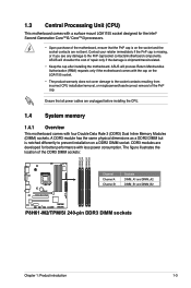
... P8H61-M2/TPM/SI Channel Channel A Channel B Sockets DIMM_A1 and DIMM_A2 DIMM_B1 and DIMM_B2 P8H61-M2/TPM/SI 240-pin DDR3 DIMM sockets Chapter 1: Product introduction 1-3 Contact your retailer immediately if the PnP cap is shipment/transit-related. • Keep the cap after installing the motherboard. ASUS ...motherboard, ensure that all power cables are not bent. The figure illustrates the location of the PnP cap. 1.3 Central Processing Unit (CPU) This motherboard comes with a surface mount LGA1155 socket designed for better performance with four Double Data Rate 3 (DDR3)...
... P8H61-M2/TPM/SI Channel Channel A Channel B Sockets DIMM_A1 and DIMM_A2 DIMM_B1 and DIMM_B2 P8H61-M2/TPM/SI 240-pin DDR3 DIMM sockets Chapter 1: Product introduction 1-3 Contact your retailer immediately if the PnP cap is shipment/transit-related. • Keep the cap after installing the motherboard. ASUS ...motherboard, ensure that all power cables are not bent. The figure illustrates the location of the PnP cap. 1.3 Central Processing Unit (CPU) This motherboard comes with a surface mount LGA1155 socket designed for better performance with four Double Data Rate 3 (DDR3)...
User Manual
Page 19
Remove the system unit cover (if your motherboard is completely seated on shared slots, ensure that the drivers support "Share IRQ" or that the cards do so may need ...
Remove the system unit cover (if your motherboard is completely seated on shared slots, ensure that the drivers support "Share IRQ" or that the cards do so may need ...
User Manual
Page 22
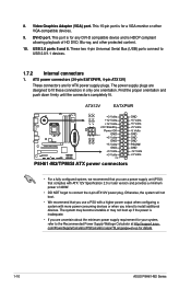
...orientation. com/PowerSupplyCalculator/PSCalculator.aspx?SLanguage=en-us for your system, refer to the Recommended Power Supply Wattage Calculator at http://support.asus. USB 2.0 ports 5 and 6. The system may become unstable or may not boot up if the power is for ATX ...1 GND +5 Volts +5 Volts +5 Volts -5 Volts GND GND GND PSON# GND -12 Volts +3 Volts P8H61-M2/TPM/SI ATX power connectors • For a fully configured system, we recommend that you use a power supply unit (PSU) that you are designed to USB 2.0/1.1 devices. 1.7.2 Internal connectors 1. This 15-pin port is ...
...orientation. com/PowerSupplyCalculator/PSCalculator.aspx?SLanguage=en-us for your system, refer to the Recommended Power Supply Wattage Calculator at http://support.asus. USB 2.0 ports 5 and 6. The system may become unstable or may not boot up if the power is for ATX ...1 GND +5 Volts +5 Volts +5 Volts -5 Volts GND GND GND PSON# GND -12 Volts +3 Volts P8H61-M2/TPM/SI ATX power connectors • For a fully configured system, we recommend that you use a power supply unit (PSU) that you are designed to USB 2.0/1.1 devices. 1.7.2 Internal connectors 1. This 15-pin port is ...


