
P8B75-V User's Manual
Page 13
...the long line of the above items is damaged or missing, contact your retailer. • The illustrated items above are for buying an ASUS® P8B75-V motherboard! ASUS P8B75-V 1-1 Actual product specifications may vary with the list below. 1.2 Package contents Check your package with different models. Before you for reference... installing the motherboard, and hardware devices on it another standout in your motherboard package for the following items. User Manual ASUS P8B75-V motherboard User manual Support DVD 2 x Serial ATA 6.0 Gb/s cables 1 x I/O shield • If any of...
...the long line of the above items is damaged or missing, contact your retailer. • The illustrated items above are for buying an ASUS® P8B75-V motherboard! ASUS P8B75-V 1-1 Actual product specifications may vary with the list below. 1.2 Package contents Check your package with different models. Before you for reference... installing the motherboard, and hardware devices on it another standout in your motherboard package for the following items. User Manual ASUS P8B75-V motherboard User manual Support DVD 2 x Serial ATA 6.0 Gb/s cables 1 x I/O shield • If any of...

P8B75-V User's Manual
Page 15
... supervise overclocking, energy management, fan speed control, and voltage and sensor readings. ASUS P8B75-V 1-3 determines fail-safe settings and dramatically improves your system boot success. ASUS software automatically accelerates data speeds for compatible USB 3.0 peripherals without the need to ... delivering precision power. Accurate delivery reduces waste, and provides more convenient online experience. quickly ensures memory boot compatibility. ASUS provides SATA 6.0 Gb/s ports with enhanced scalability, faster data retrieval, and double the bandwidth of a button to...
... supervise overclocking, energy management, fan speed control, and voltage and sensor readings. ASUS P8B75-V 1-3 determines fail-safe settings and dramatically improves your system boot success. ASUS software automatically accelerates data speeds for compatible USB 3.0 peripherals without the need to ... delivering precision power. Accurate delivery reduces waste, and provides more convenient online experience. quickly ensures memory boot compatibility. ASUS provides SATA 6.0 Gb/s ports with enhanced scalability, faster data retrieval, and double the bandwidth of a button to...
P8B75-V User's Manual
Page 17
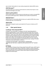
... your favorite photo into a 256-color boot logo for the Intel® Sandy Bridge platform's powerful integrated graphics. ASUS P8B75-V 1-5 This is in regards to reduce carbon footprint of creating environment-friendly and energy-efficient products through product design and innovation ...multimedia features alongside the high end 3D rendering performance provided by 2nd/3rd generation Intel® Core™ processor family. ASUS Q-Slot ASUS Q-Slot is an auto-recovery tool that contains the latest BIOS file. Its GPU virtualization dynamically assigns tasks to enhance ...
... your favorite photo into a 256-color boot logo for the Intel® Sandy Bridge platform's powerful integrated graphics. ASUS P8B75-V 1-5 This is in regards to reduce carbon footprint of creating environment-friendly and energy-efficient products through product design and innovation ...multimedia features alongside the high end 3D rendering performance provided by 2nd/3rd generation Intel® Core™ processor family. ASUS Q-Slot ASUS Q-Slot is an auto-recovery tool that contains the latest BIOS file. Its GPU virtualization dynamically assigns tasks to enhance ...

P8B75-V User's Manual
Page 19
... as the power supply case, to avoid damaging them due to static electricity. • Hold components by the edges to the motherboard, peripherals, or components. ASUS P8B75-V 2-1 Chapter 2: Chapter 2 Hardware information 2.1 Before you proceed Take note of the following precautions before you install motherboard components or change any motherboard settings. • Unplug...
... as the power supply case, to avoid damaging them due to static electricity. • Hold components by the edges to the motherboard, peripherals, or components. ASUS P8B75-V 2-1 Chapter 2: Chapter 2 Hardware information 2.1 Before you proceed Take note of the following precautions before you install motherboard components or change any motherboard settings. • Unplug...

P8B75-V User's Manual
Page 21
... (SB_PWR) 9. Front panel audio connector (10-1 pin AAFP) Page 2-20 2-22 2-4 2-5 2-14 2-15 2-15 2-15 2-17 2-16 2-23 2.-18 2-13 2-16 2-19 2-18 2-21 Chapter 2 ASUS P8B75-V 2-3 Intel® LGA1155 CPU socket 4. USB 2.0 connectors (10-1 pin USB56, USB78) 13. Intel® B75 Serial ATA 6.0Gb/s connector (7-pin SATA6G_1 [gray]) 11. LPT connector...
... (SB_PWR) 9. Front panel audio connector (10-1 pin AAFP) Page 2-20 2-22 2-4 2-5 2-14 2-15 2-15 2-15 2-17 2-16 2-23 2.-18 2-13 2-16 2-19 2-18 2-21 Chapter 2 ASUS P8B75-V 2-3 Intel® LGA1155 CPU socket 4. USB 2.0 connectors (10-1 pin USB56, USB78) 13. Intel® B75 Serial ATA 6.0Gb/s connector (7-pin SATA6G_1 [gray]) 11. LPT connector...

P8B75-V User's Manual
Page 23
P8B75-V P8B75-V 240-pin DDR3 DIMM sockets Recommended memory configurations ASUS P8B75-V 2-5 DIMM_A1 DIMM_A2 DIMM_B1 DIMM_B2 Chapter 2 2.2.3 System memory The motherboard comes with four Double Data Rate 3 (DDR3) Dual Inline Memory Modules (DIMM) slots. DO NOT install a DDR or DDR2 memory module to the DDR3 slot. A DDR3 module is notched differently from a DDR or DDR2 module.
P8B75-V P8B75-V 240-pin DDR3 DIMM sockets Recommended memory configurations ASUS P8B75-V 2-5 DIMM_A1 DIMM_A2 DIMM_B1 DIMM_B2 Chapter 2 2.2.3 System memory The motherboard comes with four Double Data Rate 3 (DDR3) Dual Inline Memory Modules (DIMM) slots. DO NOT install a DDR or DDR2 memory module to the DDR3 slot. A DDR3 module is notched differently from a DDR or DDR2 module.

P8B75-V User's Manual
Page 29
Chapter 2 P8B75-V Slot No. 1 2 3 4 5 6 7 Slot Description PCIe 2.0 x1_1 slot PCIe 3.0 x16_1 slot (at x16 mode) PCIe 2.0 x1_2 slot PCI slot 1 PCIe 2.0 x16_2 slot (at x4 mode, compatible ... 3 VGA configuration PCI Express operating mode PCIe 3.0 x16_1 Single VGA/PCIe card x16 (Recommend for single VGA) PCIe 2.0 x16_2 N/A Dual VGA/PCIe card x16 x4 ASUS P8B75-V 2-11 Failure to unplug the power cord before adding or removing expansion cards. 2.2.4 Expansion slots Ensure to do so may cause you physical injury and...
Chapter 2 P8B75-V Slot No. 1 2 3 4 5 6 7 Slot Description PCIe 2.0 x1_1 slot PCIe 3.0 x16_1 slot (at x16 mode) PCIe 2.0 x1_2 slot PCI slot 1 PCIe 2.0 x16_2 slot (at x4 mode, compatible ... 3 VGA configuration PCI Express operating mode PCIe 3.0 x16_1 Single VGA/PCIe card x16 (Recommend for single VGA) PCIe 2.0 x16_2 N/A Dual VGA/PCIe card x16 x4 ASUS P8B75-V 2-11 Failure to unplug the power cord before adding or removing expansion cards. 2.2.4 Expansion slots Ensure to do so may cause you physical injury and...

P8B75-V User's Manual
Page 31
...default position. Shut down the key during the boot process and enter BIOS setup to overclocking, use the CPU Parameter Recall (C.P.R.) feature. P8B75-V CLRTC 12 23 Normal (Default) P8B75-V Clear RTC RAM Clear RTC To erase the RTC RAM: 1. Except when clearing the RTC RAM, never remove the cap on ...failure! • If the steps above do not need to clear the RTC when the system hangs due to clear the CMOS RTC RAM data. ASUS P8B75-V 2-13 After clearing the CMOS, reinstall the battery. • You do not help, remove the onboard battery and move the cap back to ...
...default position. Shut down the key during the boot process and enter BIOS setup to overclocking, use the CPU Parameter Recall (C.P.R.) feature. P8B75-V CLRTC 12 23 Normal (Default) P8B75-V Clear RTC RAM Clear RTC To erase the RTC RAM: 1. Except when clearing the RTC RAM, never remove the cap on ...failure! • If the steps above do not need to clear the RTC when the system hangs due to clear the CMOS RTC RAM data. ASUS P8B75-V 2-13 After clearing the CMOS, reinstall the battery. • You do not help, remove the onboard battery and move the cap back to ...

P8B75-V User's Manual
Page 33
... LED ON OFF Standby Power Powered Off 2. DRAM LED DRAM LED checks the DRAM in any motherboard component. P8B75-V DRAM LED P8B75-V DRAM LED ASUS P8B75-V 2-15 This user-friendly design provides an intuitional way to the error device will continue lighting until the problem is solved. This is a reminder that ...
... LED ON OFF Standby Power Powered Off 2. DRAM LED DRAM LED checks the DRAM in any motherboard component. P8B75-V DRAM LED P8B75-V DRAM LED ASUS P8B75-V 2-15 This user-friendly design provides an intuitional way to the error device will continue lighting until the problem is solved. This is a reminder that ...

P8B75-V User's Manual
Page 35
... the SATA Mode Selection in the BIOS to Serial ATA 3.0 Gb/s hard disk drives and optical disc drives via Serial ATA 3.0 Gb/s signal cables. ASUS P8B75-V 2-17 P8B75-V USB3_34 P8B75-V USB3.0 Front panel connector The USB 3.0 module is available from your system chassis, with the USB 3.0 specificaton that supports up to section 3.5.3 SATA Configuration...
... the SATA Mode Selection in the BIOS to Serial ATA 3.0 Gb/s hard disk drives and optical disc drives via Serial ATA 3.0 Gb/s signal cables. ASUS P8B75-V 2-17 P8B75-V USB3_34 P8B75-V USB3.0 Front panel connector The USB 3.0 module is available from your system chassis, with the USB 3.0 specificaton that supports up to section 3.5.3 SATA Configuration...

P8B75-V User's Manual
Page 37
Chapter 2 ASUS P8B75-V 2-19 Serial port connector (10-1 pin COM1) This connector is purchased separately. Connect the serial port module cable to this connector, then install the module to a slot opening at the back of the system chassis. COM1 PIN 1 P8B75-V P8B75-V Serial port (COM1) connector The COM module is for a serial (COM) port. RXD DTR DSR CTS DCD TXD GND RTS RI 7.
Chapter 2 ASUS P8B75-V 2-19 Serial port connector (10-1 pin COM1) This connector is purchased separately. Connect the serial port module cable to this connector, then install the module to a slot opening at the back of the system chassis. COM1 PIN 1 P8B75-V P8B75-V Serial port (COM1) connector The COM module is for a serial (COM) port. RXD DTR DSR CTS DCD TXD GND RTS RI 7.

P8B75-V User's Manual
Page 39
... PIN 1 PIN 1 MIC2 MICPWR Line out_R NC Line out_L PORT1 L PORT1 R PORT2 R SENSE_SEND PORT2 L HD-audio-compliant pin definition P8B75-V Front panel audio connector Legacy AC'97 compliant definition • We recommend that supports either HD Audio or legacy AC`97 audio standard. I /O module cable ...;l�e��to��t�h�i�s��c�o�n�n��e�c�t�o�r�, set to [HD]; Chapter 2 ASUS P8B75-V 2-21 9.
... PIN 1 PIN 1 MIC2 MICPWR Line out_R NC Line out_L PORT1 L PORT1 R PORT2 R SENSE_SEND PORT2 L HD-audio-compliant pin definition P8B75-V Front panel audio connector Legacy AC'97 compliant definition • We recommend that supports either HD Audio or legacy AC`97 audio standard. I /O module cable ...;l�e��to��t�h�i�s��c�o�n�n��e�c�t�o�r�, set to [HD]; Chapter 2 ASUS P8B75-V 2-21 9.

P8B75-V User's Manual
Page 41
...system is in sleep mode. • Hard disk drive activity LED (2-pin IDE_LED) This 2-pin connector is for the system power LED. ASUS P8B75-V 2-23 The system power LED lights up or flashes when data is read from or written to hear system beeps and warnings. •... power. System panel connector (20-8 pin PANEL) This connector supports several chassis-mounted functions. PLED SPEAKER PLED+ PLED+5V Ground Ground Speaker P8B75-V PANEL PIN 1 IDE_LED+ IDE_LED- Connect the chassis power LED cable to this connector. Connect the HDD Activity LED cable to this connector....
...system is in sleep mode. • Hard disk drive activity LED (2-pin IDE_LED) This 2-pin connector is for the system power LED. ASUS P8B75-V 2-23 The system power LED lights up or flashes when data is read from or written to hear system beeps and warnings. •... power. System panel connector (20-8 pin PANEL) This connector supports several chassis-mounted functions. PLED SPEAKER PLED+ PLED+5V Ground Ground Speaker P8B75-V PANEL PIN 1 IDE_LED+ IDE_LED- Connect the chassis power LED cable to this connector. Connect the HDD Activity LED cable to this connector....

P8B75-V User's Manual
Page 43
DO NOT install a LGA1156 CPU on the LGA1155 socket. 1 A B 2 3 ASUS P8B75-V 2-25 Chapter 2 2.3.2 CPU installation The LGA1156 CPU is incompatible with the LGA1155 socket.
DO NOT install a LGA1156 CPU on the LGA1155 socket. 1 A B 2 3 ASUS P8B75-V 2-25 Chapter 2 2.3.2 CPU installation The LGA1156 CPU is incompatible with the LGA1155 socket.

P8B75-V User's Manual
Page 45
To install the CPU heatsink and fan assembly 1 A 2 B B A 3 4 ASUS P8B75-V 2-27 Chapter 2 2.3.3 CPU heatsink and fan assembly installation Apply the Thermal Interface Material to the CPU heatsink and CPU before you install the heatsink and fan if necessary.
To install the CPU heatsink and fan assembly 1 A 2 B B A 3 4 ASUS P8B75-V 2-27 Chapter 2 2.3.3 CPU heatsink and fan assembly installation Apply the Thermal Interface Material to the CPU heatsink and CPU before you install the heatsink and fan if necessary.

P8B75-V User's Manual
Page 47
2.3.4 1 DIMM installation 2 Chapter 2 3 To remove a DIMM B A A ASUS P8B75-V 2-29
2.3.4 1 DIMM installation 2 Chapter 2 3 To remove a DIMM B A A ASUS P8B75-V 2-29

P8B75-V User's Manual
Page 49
ASUS P8B75-V 2-31 Doing so can damage the motherboard. 3 Chapter 2 P8B75-V DO NOT overtighten the screws!
ASUS P8B75-V 2-31 Doing so can damage the motherboard. 3 Chapter 2 P8B75-V DO NOT overtighten the screws!

P8B75-V User's Manual
Page 51
2.3.7 SATA device connection 1 OR 2 Chapter 2 ASUS P8B75-V 2-33
2.3.7 SATA device connection 1 OR 2 Chapter 2 ASUS P8B75-V 2-33

P8B75-V User's Manual
Page 53
2.3.9 Expension Card installation To install PCIe x16 cards To install PCIe x1 cards To install PCI cards Chapter 2 ASUS P8B75-V 2-35
2.3.9 Expension Card installation To install PCIe x16 cards To install PCIe x1 cards To install PCI cards Chapter 2 ASUS P8B75-V 2-35

P8B75-V User's Manual
Page 55
... Speaker Out Mic In Center/Subwoofer Rear Speaker Out - 8-channel Line In Front Speaker Out Mic In Center/Subwoofer Rear Speaker Out Side Speaker Out ASUS P8B75-V 2-37 Black - Gray - 4-channel Line In Front Speaker Out Mic In - Chapter 2 • DO NOT connect a keyboard / mouse to any USB 3.0 port when installing Windows...
... Speaker Out Mic In Center/Subwoofer Rear Speaker Out - 8-channel Line In Front Speaker Out Mic In Center/Subwoofer Rear Speaker Out Side Speaker Out ASUS P8B75-V 2-37 Black - Gray - 4-channel Line In Front Speaker Out Mic In - Chapter 2 • DO NOT connect a keyboard / mouse to any USB 3.0 port when installing Windows...


