
P8B75-V User's Manual
Page 13
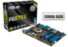
... features and latest technologies, making it , check the items in the long line of the above are for reference only. ASUS P8B75-V 1-1 Actual product specifications may vary with the list below. 1.2 Package contents Check your retailer. • The illustrated items ... contact your motherboard package for buying an ASUS® P8B75-V motherboard! Before you for the following items. User Manual ASUS P8B75-V motherboard User manual Support DVD 2 x Serial ATA 6.0 Gb/s cables 1 x I/O shield • If any of ASUS quality motherboards! Thank you start installing the...
... features and latest technologies, making it , check the items in the long line of the above are for reference only. ASUS P8B75-V 1-1 Actual product specifications may vary with the list below. 1.2 Package contents Check your retailer. • The illustrated items ... contact your motherboard package for buying an ASUS® P8B75-V motherboard! Before you for the following items. User Manual ASUS P8B75-V motherboard User manual Support DVD 2 x Serial ATA 6.0 Gb/s cables 1 x I/O shield • If any of ASUS quality motherboards! Thank you start installing the...

P8B75-V User's Manual
Page 15
...All High-quality Conductive Polymer Capacitors This motherboard uses all -in no need for durability, improved lifespan, and enhanced thermal capacity. 1.3.2 ASUS Exclusive Features DIGI+ VRM - MemOK! Get your system up to 6.0 Gb/s data transfer. USB 3.0 Boost With USB 3.0 ...This all high-quality conductive polymer capacitors for any user interaction. ASUS provides SATA 6.0 Gb/s ports with accurate input through UEFI BIOS tuning or the exclusive ASUS interface. ASUS P8B75-V 1-3 ASUS software automatically accelerates data speeds for compatible USB 3.0 peripherals without ...
...All High-quality Conductive Polymer Capacitors This motherboard uses all -in no need for durability, improved lifespan, and enhanced thermal capacity. 1.3.2 ASUS Exclusive Features DIGI+ VRM - MemOK! Get your system up to 6.0 Gb/s data transfer. USB 3.0 Boost With USB 3.0 ...This all high-quality conductive polymer capacitors for any user interaction. ASUS provides SATA 6.0 Gb/s ports with accurate input through UEFI BIOS tuning or the exclusive ASUS interface. ASUS P8B75-V 1-3 ASUS software automatically accelerates data speeds for compatible USB 3.0 peripherals without ...
P8B75-V User's Manual
Page 17
...ASUS EZ-Flash 2 ASUS... a user-friendly utility that contains the latest BIOS file. ASUS Q-Slot ASUS Q-Slot is designed to speed up and simplify the DIY...more colorful and vivid image on Windows® 7 based PCs. ASUS MyLogo2™ This feature allows you to fully utilize the unique... 2nd/3rd generation Intel® Core™ processor family. ASUS CrashFree BIOS 3 ASUS CrashFree BIOS 3 is put in line with diverse needs,...Video feature is supported by installed graphics cards. For users with ASUS vision of creating environment-friendly and energy-efficient products through product design...
...ASUS EZ-Flash 2 ASUS... a user-friendly utility that contains the latest BIOS file. ASUS Q-Slot ASUS Q-Slot is designed to speed up and simplify the DIY...more colorful and vivid image on Windows® 7 based PCs. ASUS MyLogo2™ This feature allows you to fully utilize the unique... 2nd/3rd generation Intel® Core™ processor family. ASUS CrashFree BIOS 3 ASUS CrashFree BIOS 3 is put in line with diverse needs,...Video feature is supported by installed graphics cards. For users with ASUS vision of creating environment-friendly and energy-efficient products through product design...

P8B75-V User's Manual
Page 19
...; Whenever you uninstall any component, place it on them due to static electricity. • Hold components by the edges to the motherboard, peripherals, or components. ASUS P8B75-V 2-1
...; Whenever you uninstall any component, place it on them due to static electricity. • Hold components by the edges to the motherboard, peripherals, or components. ASUS P8B75-V 2-1

P8B75-V User's Manual
Page 21
... socket 4. Front panel audio connector (10-1 pin AAFP) Page 2-20 2-22 2-4 2-5 2-14 2-15 2-15 2-15 2-17 2-16 2-23 2.-18 2-13 2-16 2-19 2-18 2-21 Chapter 2 ASUS P8B75-V 2-3 CPU and chassis connectors (4-pin CPU_FAN, 4-pin CHA_FAN1/2) 2. Intel® B75 Serial ATA 3.0Gb/s connectors (7-pin SATA3G_1~5 [blue]) 10. Clear RTC RAM (3-pin CLRTC) 14...
... socket 4. Front panel audio connector (10-1 pin AAFP) Page 2-20 2-22 2-4 2-5 2-14 2-15 2-15 2-15 2-17 2-16 2-23 2.-18 2-13 2-16 2-19 2-18 2-21 Chapter 2 ASUS P8B75-V 2-3 CPU and chassis connectors (4-pin CPU_FAN, 4-pin CHA_FAN1/2) 2. Intel® B75 Serial ATA 3.0Gb/s connectors (7-pin SATA3G_1~5 [blue]) 10. Clear RTC RAM (3-pin CLRTC) 14...

P8B75-V User's Manual
Page 23
A DDR3 module is notched differently from a DDR or DDR2 module. P8B75-V P8B75-V 240-pin DDR3 DIMM sockets Recommended memory configurations ASUS P8B75-V 2-5 DO NOT install a DDR or DDR2 memory module to the DDR3 slot. DIMM_A1 DIMM_A2 DIMM_B1 DIMM_B2 Chapter 2 2.2.3 System memory The motherboard comes with four Double Data Rate 3 (DDR3) Dual Inline Memory Modules (DIMM) slots.
A DDR3 module is notched differently from a DDR or DDR2 module. P8B75-V P8B75-V 240-pin DDR3 DIMM sockets Recommended memory configurations ASUS P8B75-V 2-5 DO NOT install a DDR or DDR2 memory module to the DDR3 slot. DIMM_A1 DIMM_A2 DIMM_B1 DIMM_B2 Chapter 2 2.2.3 System memory The motherboard comes with four Double Data Rate 3 (DDR3) Dual Inline Memory Modules (DIMM) slots.

P8B75-V User's Manual
Page 29
Chapter 2 P8B75-V Slot No. 1 2 3 4 5 6 7 Slot Description PCIe 2.0 x1_1 slot PCIe 3.0 x16_1 slot (at x16 mode) PCIe 2.0 x1_2 slot PCI slot 1 PCIe 2.0 x16_2 slot (at x4 mode, compatible ... 3 VGA configuration PCI Express operating mode PCIe 3.0 x16_1 Single VGA/PCIe card x16 (Recommend for single VGA) PCIe 2.0 x16_2 N/A Dual VGA/PCIe card x16 x4 ASUS P8B75-V 2-11 2.2.4 Expansion slots Ensure to do so may cause you physical injury and damage motherboard components. Failure to unplug the power cord before adding or...
Chapter 2 P8B75-V Slot No. 1 2 3 4 5 6 7 Slot Description PCIe 2.0 x1_1 slot PCIe 3.0 x16_1 slot (at x16 mode) PCIe 2.0 x1_2 slot PCI slot 1 PCIe 2.0 x16_2 slot (at x4 mode, compatible ... 3 VGA configuration PCI Express operating mode PCIe 3.0 x16_1 Single VGA/PCIe card x16 (Recommend for single VGA) PCIe 2.0 x16_2 N/A Dual VGA/PCIe card x16 x4 ASUS P8B75-V 2-11 2.2.4 Expansion slots Ensure to do so may cause you physical injury and damage motherboard components. Failure to unplug the power cord before adding or...

P8B75-V User's Manual
Page 31
.... Hold down and reboot the system, then the BIOS automatically resets parameter settings to pins 2-3. For system failure due to reenter data. ASUS P8B75-V 2-13 P8B75-V CLRTC 12 23 Normal (Default) P8B75-V Clear RTC RAM Clear RTC To erase the RTC RAM: 1. Keep the cap on CLRTC jumper default position. Except when clearing the...
.... Hold down and reboot the system, then the BIOS automatically resets parameter settings to pins 2-3. For system failure due to reenter data. ASUS P8B75-V 2-13 P8B75-V CLRTC 12 23 Normal (Default) P8B75-V Clear RTC RAM Clear RTC To erase the RTC RAM: 1. Keep the cap on CLRTC jumper default position. Except when clearing the...

P8B75-V User's Manual
Page 33
This is solved. The illustration below shows the location of the onboard LED. P8B75-V DRAM LED P8B75-V DRAM LED ASUS P8B75-V 2-15 P8B75-V SB_PWR P8B75-V Onboard LED ON OFF Standby Power Powered Off 2. If an error is found , the LED next to the error device will continue lighting until the ...
This is solved. The illustration below shows the location of the onboard LED. P8B75-V DRAM LED P8B75-V DRAM LED ASUS P8B75-V 2-15 P8B75-V SB_PWR P8B75-V Onboard LED ON OFF Standby Power Powered Off 2. If an error is found , the LED next to the error device will continue lighting until the ...

P8B75-V User's Manual
Page 35
... GND RSATA_RXN2 RSATA_RXP2 GND GND RSATA_TXP1 RSATA_TXN1 GND RSATA_RXN1 RSATA_RXP1 GND P8B75-V SATA3G_5 SATA3G_4 GND RSATA_RXP5 RSATA_RXN5 GND RSATA_TXN5 RSATA_TXP5 GND GND RSATA_RXP4 RSATA_RXN4 GND RSATA_TXN4 RSATA_TXP4 GND P8B75-V SATA 3.0Gb/s connectors When using NCQ, set the SATA...complies with this USB 3.0 connector, you can have a front panel USB 3.0 solution. ASUS P8B75-V 2-17 Chapter 2 3. USB 3.0 connector (20-1 pin USB3_34) This connector is for details. 4. P8B75-V USB3_34 P8B75-V USB3.0 Front panel connector The USB 3.0 module is available from your system chassis, with...
... GND RSATA_RXN2 RSATA_RXP2 GND GND RSATA_TXP1 RSATA_TXN1 GND RSATA_RXN1 RSATA_RXP1 GND P8B75-V SATA3G_5 SATA3G_4 GND RSATA_RXP5 RSATA_RXN5 GND RSATA_TXN5 RSATA_TXP5 GND GND RSATA_RXP4 RSATA_RXN4 GND RSATA_TXN4 RSATA_TXP4 GND P8B75-V SATA 3.0Gb/s connectors When using NCQ, set the SATA...complies with this USB 3.0 connector, you can have a front panel USB 3.0 solution. ASUS P8B75-V 2-17 Chapter 2 3. USB 3.0 connector (20-1 pin USB3_34) This connector is for details. 4. P8B75-V USB3_34 P8B75-V USB3.0 Front panel connector The USB 3.0 module is available from your system chassis, with...

P8B75-V User's Manual
Page 37
Chapter 2 ASUS P8B75-V 2-19 Connect the serial port module cable to this connector, then install the module to a slot opening at the back of the system chassis. RXD DTR DSR CTS DCD TXD GND RTS RI 7. Serial port connector (10-1 pin COM1) This connector is purchased separately. COM1 PIN 1 P8B75-V P8B75-V Serial port (COM1) connector The COM module is for a serial (COM) port.
Chapter 2 ASUS P8B75-V 2-19 Connect the serial port module cable to this connector, then install the module to a slot opening at the back of the system chassis. RXD DTR DSR CTS DCD TXD GND RTS RI 7. Serial port connector (10-1 pin COM1) This connector is purchased separately. COM1 PIN 1 P8B75-V P8B75-V Serial port (COM1) connector The COM module is for a serial (COM) port.

P8B75-V User's Manual
Page 39
...a chassis-mounted front panel audio I /O module cable to this connector, set the Front Panel Type item in the BIOS setup to [HD]. Chapter 2 ASUS P8B75-V 2-21 Front panel audio connector (10-1 pin AAFP) This connector is set to [HD]; 9. Connect one end of the motherboard's high-definition audio ...capability. AGND NC SENSE1_RETUR SENSE2_RETUR AGND NC NC NC P8B75-V AAFP PIN 1 PIN 1 MIC2 MICPWR Line out_R NC Line out_L PORT1 L PORT1 R PORT2 R SENSE_SEND PORT2 L HD-audio-compliant pin definition...
...a chassis-mounted front panel audio I /O module cable to this connector, set the Front Panel Type item in the BIOS setup to [HD]. Chapter 2 ASUS P8B75-V 2-21 Front panel audio connector (10-1 pin AAFP) This connector is set to [HD]; 9. Connect one end of the motherboard's high-definition audio ...capability. AGND NC SENSE1_RETUR SENSE2_RETUR AGND NC NC NC P8B75-V AAFP PIN 1 PIN 1 MIC2 MICPWR Line out_R NC Line out_L PORT1 L PORT1 R PORT2 R SENSE_SEND PORT2 L HD-audio-compliant pin definition...

P8B75-V User's Manual
Page 41
... PIN 1 IDE_LED+ IDE_LED- PWR Ground Reset Ground IDE_LED PWRSW RESET * Requires an ATX power supply P8B75-V System panel connector • System power LED (2-pin PLED) This 2-pin connector is for the chassis-mounted reset button for the chassis-mounted system warning .... The IDE LED lights up when you to the HDD. • System warning speaker (4-pin SPEAKER) This 4-pin connector is for the system power LED. ASUS P8B75-V 2-23 The speaker allows you turn on the system power, and blinks when the system is in sleep mode. • Hard disk drive activity LED...
... PIN 1 IDE_LED+ IDE_LED- PWR Ground Reset Ground IDE_LED PWRSW RESET * Requires an ATX power supply P8B75-V System panel connector • System power LED (2-pin PLED) This 2-pin connector is for the chassis-mounted reset button for the chassis-mounted system warning .... The IDE LED lights up when you to the HDD. • System warning speaker (4-pin SPEAKER) This 4-pin connector is for the system power LED. ASUS P8B75-V 2-23 The speaker allows you turn on the system power, and blinks when the system is in sleep mode. • Hard disk drive activity LED...

P8B75-V User's Manual
Page 43
Chapter 2 2.3.2 CPU installation The LGA1156 CPU is incompatible with the LGA1155 socket. DO NOT install a LGA1156 CPU on the LGA1155 socket. 1 A B 2 3 ASUS P8B75-V 2-25
Chapter 2 2.3.2 CPU installation The LGA1156 CPU is incompatible with the LGA1155 socket. DO NOT install a LGA1156 CPU on the LGA1155 socket. 1 A B 2 3 ASUS P8B75-V 2-25

P8B75-V User's Manual
Page 45
To install the CPU heatsink and fan assembly 1 A 2 B B A 3 4 ASUS P8B75-V 2-27 Chapter 2 2.3.3 CPU heatsink and fan assembly installation Apply the Thermal Interface Material to the CPU heatsink and CPU before you install the heatsink and fan if necessary.
To install the CPU heatsink and fan assembly 1 A 2 B B A 3 4 ASUS P8B75-V 2-27 Chapter 2 2.3.3 CPU heatsink and fan assembly installation Apply the Thermal Interface Material to the CPU heatsink and CPU before you install the heatsink and fan if necessary.

P8B75-V User's Manual
Page 47
2.3.4 1 DIMM installation 2 Chapter 2 3 To remove a DIMM B A A ASUS P8B75-V 2-29
2.3.4 1 DIMM installation 2 Chapter 2 3 To remove a DIMM B A A ASUS P8B75-V 2-29

P8B75-V User's Manual
Page 49
ASUS P8B75-V 2-31 Doing so can damage the motherboard. 3 Chapter 2 P8B75-V DO NOT overtighten the screws!
ASUS P8B75-V 2-31 Doing so can damage the motherboard. 3 Chapter 2 P8B75-V DO NOT overtighten the screws!

P8B75-V User's Manual
Page 51
2.3.7 SATA device connection 1 OR 2 Chapter 2 ASUS P8B75-V 2-33
2.3.7 SATA device connection 1 OR 2 Chapter 2 ASUS P8B75-V 2-33

P8B75-V User's Manual
Page 53
2.3.9 Expension Card installation To install PCIe x16 cards To install PCIe x1 cards To install PCI cards Chapter 2 ASUS P8B75-V 2-35
2.3.9 Expension Card installation To install PCIe x16 cards To install PCIe x1 cards To install PCI cards Chapter 2 ASUS P8B75-V 2-35

P8B75-V User's Manual
Page 55
... Speaker Out Mic In Center/Subwoofer Rear Speaker Out - 8-channel Line In Front Speaker Out Mic In Center/Subwoofer Rear Speaker Out Side Speaker Out ASUS P8B75-V 2-37 Gray - 4-channel Line In Front Speaker Out Mic In - Black - Chapter 2 • DO NOT connect a keyboard / mouse to any USB 3.0 port when installing Windows...
... Speaker Out Mic In Center/Subwoofer Rear Speaker Out - 8-channel Line In Front Speaker Out Mic In Center/Subwoofer Rear Speaker Out Side Speaker Out ASUS P8B75-V 2-37 Gray - 4-channel Line In Front Speaker Out Mic In - Black - Chapter 2 • DO NOT connect a keyboard / mouse to any USB 3.0 port when installing Windows...


