
User Manual
Page 31
ok A:\> 當 BIOS DOS 31 done Write to file...... Reading flash ..... exe 2 DOS afudos /o[filename filename A:\>afudos /oOLDBIOS1.rom 3. 按下 afudos /oOLDBIOS1.rom AMI Firmware Update Utility - Version 1.19(ASUS V2.07(03.11.24BB)) Copyright (C) 2002 American Megatrends, Inc. All rights reserved. BIOS 2.1 使用 AFUDOS BIOS AFUDOS DOS BIOS BIOS 程式。AFUDOS BIOS BIOS BIOS 程式 BIOS 程式。 1.2MB BIOS 1 AFUDOS 程式(afudos.
ok A:\> 當 BIOS DOS 31 done Write to file...... Reading flash ..... exe 2 DOS afudos /o[filename filename A:\>afudos /oOLDBIOS1.rom 3. 按下 afudos /oOLDBIOS1.rom AMI Firmware Update Utility - Version 1.19(ASUS V2.07(03.11.24BB)) Copyright (C) 2002 American Megatrends, Inc. All rights reserved. BIOS 2.1 使用 AFUDOS BIOS AFUDOS DOS BIOS BIOS 程式。AFUDOS BIOS BIOS BIOS 程式 BIOS 程式。 1.2MB BIOS 1 AFUDOS 程式(afudos.

User Manual
Page 32
... Utility - Erasing flash ...... WARNING!! done Reading flash ...... WARNING!! 更新 BIOS 程式 AFUDOS BIOS 程式。 1 tw.asus.com BIOS 片中。 BIOS BIOS 2. 將 AFUDOS.EXE BIOS 3 DOS afudos /i[filename filename BIOS 程式。 A:\>afudos /iP5B-VM DO.ROM 4. Erasing flash ...... Version 1.19(ASUS V2.07(03.11.24BB)) Copyright (C) 2002 American Megatrends, Inc...
... Utility - Erasing flash ...... WARNING!! done Reading flash ...... WARNING!! 更新 BIOS 程式 AFUDOS BIOS 程式。 1 tw.asus.com BIOS 片中。 BIOS BIOS 2. 將 AFUDOS.EXE BIOS 3 DOS afudos /i[filename filename BIOS 程式。 A:\>afudos /iP5B-VM DO.ROM 4. Erasing flash ...... Version 1.19(ASUS V2.07(03.11.24BB)) Copyright (C) 2002 American Megatrends, Inc...

User Manual
Page 33
... 程式(AWDFLASH.EXE BIOS AwardBIOS Flash BIOS 程式。 1 http://tw.asus.com BIOS M2N-VM HDMI.bin FAT 32/16 格式的 USB BIOS 2 CD/DVD AwardBIOS Flash BIOS 3 DOS 4. 當 A BIOS 檔案與 AwardBIOS Flash 5 A awdflash 並按下 鍵。 AwardBIOS Flash Utility for ASUS V1.14 (C) Phoenix Technologies Ltd...
... 程式(AWDFLASH.EXE BIOS AwardBIOS Flash BIOS 程式。 1 http://tw.asus.com BIOS M2N-VM HDMI.bin FAT 32/16 格式的 USB BIOS 2 CD/DVD AwardBIOS Flash BIOS 3 DOS 4. 當 A BIOS 檔案與 AwardBIOS Flash 5 A awdflash 並按下 鍵。 AwardBIOS Flash Utility for ASUS V1.14 (C) Phoenix Technologies Ltd...

User Manual
Page 34
... Flash Type - OFE00 OK Write OK No Update Write Fail Warning: Don't Turn Off Power Or Reset System! 在更新 BIOS 9 Flash Complete BIOS F1 AwardBIOS Flash Utility for ASUS V1.14 (C) Phoenix Technologies Ltd. PMC Pm49FL004T LPC/FWH File Name to Program: M2A-VM HDMI.bin Flashing Complete Press to Program...: M2A-VM HDMI.bin Programming Flash Memory - All Rights Reserved For C51PV-MCP51-M2A-VM HDMI-00 DATE:04/13/2006 Flash Type - 7 BIOS N BIOS 8 BIOS BIOS AwardBIOS Flash Utility for ASUS V1.14 (C) Phoenix Technologies Ltd.
... Flash Type - OFE00 OK Write OK No Update Write Fail Warning: Don't Turn Off Power Or Reset System! 在更新 BIOS 9 Flash Complete BIOS F1 AwardBIOS Flash Utility for ASUS V1.14 (C) Phoenix Technologies Ltd. PMC Pm49FL004T LPC/FWH File Name to Program: M2A-VM HDMI.bin Flashing Complete Press to Program...: M2A-VM HDMI.bin Programming Flash Memory - All Rights Reserved For C51PV-MCP51-M2A-VM HDMI-00 DATE:04/13/2006 Flash Type - 7 BIOS N BIOS 8 BIOS BIOS AwardBIOS Flash Utility for ASUS V1.14 (C) Phoenix Technologies Ltd.
User Manual
Page 4
... computer 2-38 2.9.1 Using the OS shut down function 2-38 2.9.2 Using the dual function power switch 2-38 Chapter 3: BIOS setup 3.1 Managing and updating your BIOS 3-1 3.1.1 ASUS Update utility 3-1 3.1.2 ASUS EZ Flash 2 utility 3-4 3.1.3 AFUDOS utility 3-5 3.1.4 ASUS CrashFree BIOS 3 utility 3-7 3.2 BIOS setup program 3-8 3.2.1 BIOS menu screen 3-9 3.2.2 Menu bar 3-9 3.2.3 Navigation keys 3-9 3.2.4 Menu items 3-10 3.2.5 Sub-menu items 3-10 3.2.6 Configuration fields 3-10 3.2.7 Pop...
... computer 2-38 2.9.1 Using the OS shut down function 2-38 2.9.2 Using the dual function power switch 2-38 Chapter 3: BIOS setup 3.1 Managing and updating your BIOS 3-1 3.1.1 ASUS Update utility 3-1 3.1.2 ASUS EZ Flash 2 utility 3-4 3.1.3 AFUDOS utility 3-5 3.1.4 ASUS CrashFree BIOS 3 utility 3-7 3.2 BIOS setup program 3-8 3.2.1 BIOS menu screen 3-9 3.2.2 Menu bar 3-9 3.2.3 Navigation keys 3-9 3.2.4 Menu items 3-10 3.2.5 Sub-menu items 3-10 3.2.6 Configuration fields 3-10 3.2.7 Pop...
User Manual
Page 9
...; Chapter 2: Hardware information This chapter lists the hardware setup procedures that you need when installing and configuring the motherboard. Detailed descriptions of the BIOS parameters are not part of the switches, jumpers, and connectors on ASUS hardware and software products. Optional documentation Your product package may include optional documentation, such as warranty flyers...
...; Chapter 2: Hardware information This chapter lists the hardware setup procedures that you need when installing and configuring the motherboard. Detailed descriptions of the BIOS parameters are not part of the switches, jumpers, and connectors on ASUS hardware and software products. Optional documentation Your product package may include optional documentation, such as warranty flyers...

User Manual
Page 12
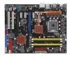
...: - ASUS CrashFree BIOS 3 - PCI Express frequency tuning from 200MHz up to 800MHz at 1MHz increment Overclocking Protection: - ASUS Q-Shield - ASUS Drive Xpert - vCore: Adjustable CPU voltage at 6.25mV increment - ASUS AI Nap ASUS Unique Features: - Profile - vChipset (N.B.): 55-step chipset voltage control - P5Q PRO specifications summary ASUS Unique Features ASUS Stylish Features ASUS Exclusive Overclocking Features ASUS Power Saving Solution: - ASUS EPU-6 Engine - ASUS...
...: - ASUS CrashFree BIOS 3 - PCI Express frequency tuning from 200MHz up to 800MHz at 1MHz increment Overclocking Protection: - ASUS Q-Shield - ASUS Drive Xpert - vCore: Adjustable CPU voltage at 6.25mV increment - ASUS AI Nap ASUS Unique Features: - Profile - vChipset (N.B.): 55-step chipset voltage control - P5Q PRO specifications summary ASUS Unique Features ASUS Stylish Features ASUS Exclusive Overclocking Features ASUS Power Saving Solution: - ASUS EPU-6 Engine - ASUS...

User Manual
Page 13
xiii P5Q PRO specifications summary Back Panel I/O Ports Internal I/O Connectors BIOS Features Manageability Support CD Contents Form Factor 1 x PS/2 Keyboard port 1 x PS/2 Mouse port 1 x S/PDIF Out (Coaxial) 1 x IEEE1394a 1 x RJ45 ports 6 x USB 2.0/1.1 8-channel Audio I/O 3 x USB...CD audio in 24-pin ATX Power connector 1 x 8-pin ATX 12V Power connectors System Panel (Q-Connector) 8 Mb Flash ROM, AMI BIOS, PnP, DMI 2.0, WfM 2.0, SM BIOS 2.4, ACPI 2.0a WOL by PME, WOR by PME, PXE, WOR by Ring, Chassis Intrusion Drivers Express Gate ASUS PC Probe II ASUS Update ASUS AI Suite Anti-virus software ...
xiii P5Q PRO specifications summary Back Panel I/O Ports Internal I/O Connectors BIOS Features Manageability Support CD Contents Form Factor 1 x PS/2 Keyboard port 1 x PS/2 Mouse port 1 x S/PDIF Out (Coaxial) 1 x IEEE1394a 1 x RJ45 ports 6 x USB 2.0/1.1 8-channel Audio I/O 3 x USB...CD audio in 24-pin ATX Power connector 1 x 8-pin ATX 12V Power connectors System Panel (Q-Connector) 8 Mb Flash ROM, AMI BIOS, PnP, DMI 2.0, WfM 2.0, SM BIOS 2.4, ACPI 2.0a WOL by PME, WOR by PME, PXE, WOR by Ring, Chassis Intrusion Drivers Express Gate ASUS PC Probe II ASUS Update ASUS AI Suite Anti-virus software ...
User Manual
Page 21
... easy ways to lower overall system temperature, resulting in the motherboard to install computer components, update the BIOS or back up to address the thermal issues across the motherboard, and most efficient manner. ASUS P5Q PRO 1-5 creating more energy efficiency. Fanless Design and Heat-pipe The ASUS fanless design allows multi-directional heat flow from major thermal...
... easy ways to lower overall system temperature, resulting in the motherboard to install computer components, update the BIOS or back up to address the thermal issues across the motherboard, and most efficient manner. ASUS P5Q PRO 1-5 creating more energy efficiency. Fanless Design and Heat-pipe The ASUS fanless design allows multi-directional heat flow from major thermal...
User Manual
Page 22
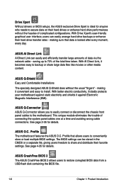
... can easily arrange hard drive backups or enhance their favorite settings. ASUS Q-Shield Easy and Comfortable Installations The specially designed ASUS Q-Shield does without the hassles of the total time taken. Profile The motherboard features the ASUS O.C. ASUS CrashFree BIOS 3 The ASUS CrashFree BIOS 3 allows users to the motherboard. Profile that data is ideal for anyone who needs to...
... can easily arrange hard drive backups or enhance their favorite settings. ASUS Q-Shield Easy and Comfortable Installations The specially designed ASUS Q-Shield does without the hassles of the total time taken. Profile The motherboard features the ASUS O.C. ASUS CrashFree BIOS 3 The ASUS CrashFree BIOS 3 allows users to the motherboard. Profile that data is ideal for anyone who needs to...

User Manual
Page 23
...motherboard BIOS allows automatic re-setting to the BIOS default settings in Windows environment without preparing a bootable diskette or using an OS-based flash utility. eliminates the need to overclock the CPU speed in case the system hangs due to overclocking, C.P.R. feature of booting the BIOS. ASUS... EZ Flash 2 EZ Flash 2 is a user-friendly BIOS update utility. ASUS P5Q PRO 1-7 Update your favorite photo into a 256-color boot logo for each parameter. When the system...
...motherboard BIOS allows automatic re-setting to the BIOS default settings in Windows environment without preparing a bootable diskette or using an OS-based flash utility. eliminates the need to overclock the CPU speed in case the system hangs due to overclocking, C.P.R. feature of booting the BIOS. ASUS... EZ Flash 2 EZ Flash 2 is a user-friendly BIOS update utility. ASUS P5Q PRO 1-7 Update your favorite photo into a 256-color boot logo for each parameter. When the system...

User Manual
Page 43
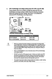
... may need to do not need IRQ assignments. Failure to install expansion cards. Remove the system unit cover (if your motherboard is completely seated on BIOS setup. 2. Keep the screw for information on the slot. 5. Replace the system cover. 2.5.2 Configuring an expansion card ... When using PCI cards on the next page. 3. Secure the card to the table on the system and change the necessary BIOS settings, if any. ASUS P5Q PRO 2-17 Before installing the expansion card, read the documentation that you removed earlier. 6. Turn on the next page for the ...
... may need to do not need IRQ assignments. Failure to install expansion cards. Remove the system unit cover (if your motherboard is completely seated on BIOS setup. 2. Keep the screw for information on the slot. 5. Replace the system cover. 2.5.2 Configuring an expansion card ... When using PCI cards on the next page. 3. Secure the card to the table on the system and change the necessary BIOS settings, if any. ASUS P5Q PRO 2-17 Before installing the expansion card, read the documentation that you removed earlier. 6. Turn on the next page for the ...

User Manual
Page 46
... due to pins 2-3. You must turn ON the computer. 4. Shut down the key during the boot process and enter BIOS setup to pins 1-2. 3. Hold down and reboot the system so the BIOS can clear the CMOS memory of date, time, and system setup parameters by erasing the CMOS RTC RAM data. 2.6 Jumper...
... due to pins 2-3. You must turn ON the computer. 4. Shut down the key during the boot process and enter BIOS setup to pins 1-2. 3. Hold down and reboot the system so the BIOS can clear the CMOS memory of date, time, and system setup parameters by erasing the CMOS RTC RAM data. 2.6 Jumper...
User Manual
Page 47
Set to pins 1-2 to adjust the desired CPU and Northbridge performance. ASUS P5Q PRO 2-21 2. Pins 2-3 (Default) Pins 1-2 (OV Enabled) OV_CPU up to 1.70V up to 2.10V OV_NB up to 1.90V up to 2.20V • Before you change the ... settings before you install a new CPU and have not booted for extra-high overvoltage ability, use the BIOS items introduced in BIOS. Make sure your system function well under high voltage settings. Read the following information before you change the jumper settings. Doing so may need a better ...
Set to pins 1-2 to adjust the desired CPU and Northbridge performance. ASUS P5Q PRO 2-21 2. Pins 2-3 (Default) Pins 1-2 (OV Enabled) OV_CPU up to 1.70V up to 2.10V OV_NB up to 1.90V up to 2.20V • Before you change the ... settings before you install a new CPU and have not booted for extra-high overvoltage ability, use the BIOS items introduced in BIOS. Make sure your system function well under high voltage settings. Read the following information before you change the jumper settings. Doing so may need a better ...
User Manual
Page 48
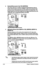
...up from S1 sleep mode (CPU stopped, DRAM refreshed, system running in low power mode) using the connected USB devices. This feature requires an ATX power supply that can supply at least 500 mA on the +5VSB lead, and a corresponding setting in sleep mode. 2-22 Chapter 2: Hardware ... to wake up . • The total current consumed must NOT exceed the power supply capability (+5VSB) whether under normal condition or in the BIOS. 4. The USBPW1-4/PS2_USBPW56 jumpers are for the rear USB ports. Keyboard/Mouse power (3-pin PS2 USBPWR56) This jumper allows you can connect to enable...
...up from S1 sleep mode (CPU stopped, DRAM refreshed, system running in low power mode) using the connected USB devices. This feature requires an ATX power supply that can supply at least 500 mA on the +5VSB lead, and a corresponding setting in sleep mode. 2-22 Chapter 2: Hardware ... to wake up . • The total current consumed must NOT exceed the power supply capability (+5VSB) whether under normal condition or in the BIOS. 4. The USBPW1-4/PS2_USBPW56 jumpers are for the rear USB ports. Keyboard/Mouse power (3-pin PS2 USBPWR56) This jumper allows you can connect to enable...
User Manual
Page 53
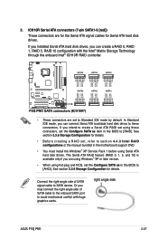
... right-angle side of SATA cable to the onboard SATA port to [AHCI]. right angle side ASUS P5Q PRO 2-27 In Standard IDE mode, you may connect the right-angle side of SATA signal cable ... you are set , refer to section 4.4.3 Intel RAID configurations or the manual bundled in the motherboard support DVD. • You must install the Windows® XP Service Pack 1 before using ... as in the BIOS to SATA device. See section 3.3.6 Storage Configuration for details. • Before creating a RAID set to these connectors, set the Configure SATA as item in the BIOS to avoid mechanical...
... right-angle side of SATA cable to the onboard SATA port to [AHCI]. right angle side ASUS P5Q PRO 2-27 In Standard IDE mode, you may connect the right-angle side of SATA signal cable ... you are set , refer to section 4.4.3 Intel RAID configurations or the manual bundled in the motherboard support DVD. • You must install the Windows® XP Service Pack 1 before using ... as in the BIOS to SATA device. See section 3.3.6 Storage Configuration for details. • Before creating a RAID set to these connectors, set the Configure SATA as item in the BIOS to avoid mechanical...
User Manual
Page 59
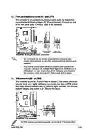
Refer to [AC97]. ASUS P5Q PRO 2-33 Connect one end of the front panel audio I /O module that the Front Panel Type item in the BIOS is set the item to page 3-27 for details. If you want to connect an AC' 97 front panel audio module to [HD Audio]. A TPM... I /O module cable to this connector. • We recommend that you connect a high-definition front panel audio module to this connector to avail of the motherboard's high-definition audio capability. • If you want to connect a high-definition front panel audio module to this connector, set to this connector, make sure...
Refer to [AC97]. ASUS P5Q PRO 2-33 Connect one end of the front panel audio I /O module that the Front Panel Type item in the BIOS is set the item to page 3-27 for details. If you want to connect an AC' 97 front panel audio module to [HD Audio]. A TPM... I /O module cable to this connector. • We recommend that you connect a high-definition front panel audio module to this connector to avail of the motherboard's high-definition audio capability. • If you want to connect a high-definition front panel audio module to this connector, set to this connector, make sure...
User Manual
Page 61
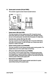
... speaker. The system power LED lights up or flashes when data is for the HDD Activity LED. 15. ASUS P5Q PRO 2-35 Connect the HDD Activity LED cable to hear system beeps and warnings. • ATX power button/soft-off the system power. The IDE LED lights up when you to this connector. Connect...; System warning speaker (4-pin SPEAKER) This 4-pin connector is read from or written to this connector. Pressing the power button turns the system on the BIOS settings.
... speaker. The system power LED lights up or flashes when data is for the HDD Activity LED. 15. ASUS P5Q PRO 2-35 Connect the HDD Activity LED cable to hear system beeps and warnings. • ATX power button/soft-off the system power. The IDE LED lights up when you to this connector. Connect...; System warning speaker (4-pin SPEAKER) This 4-pin connector is read from or written to this connector. Pressing the power button turns the system on the BIOS settings.

User Manual
Page 63
...BIOS Setup. Turn on test. External SCSI devices (starting with "green" standards or if it has a "power standby" feature, the monitor LED may light up when you turned on the power, the system may have failed a power-on the devices in Chapter 3. Follow the instructions in the following order: a. ASUS P5Q PRO... protector. 5. Monitor b. After making all switches are running, the BIOS beeps (see anything within 30 seconds from the time you press the ATX power button. Be sure that is equipped with ATX power supplies, the system LED lights up or switch between orange and...
...BIOS Setup. Turn on test. External SCSI devices (starting with "green" standards or if it has a "power standby" feature, the monitor LED may light up when you turned on the power, the system may have failed a power-on the devices in Chapter 3. Follow the instructions in the following order: a. ASUS P5Q PRO... protector. 5. Monitor b. After making all switches are running, the BIOS beeps (see anything within 30 seconds from the time you press the ATX power button. Be sure that is equipped with ATX power supplies, the system LED lights up or switch between orange and...
User Manual
Page 64
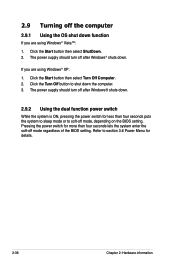
...using Windows® Vista™: 1. Pressing the power switch for less than four seconds lets the system enter the soft-off mode regardless of the BIOS setting. The power supply should turn off after Windows® shuts down. Click the Turn Off button to section 3.6 Power Menu for details. 2-38... is ON, pressing the power switch for more than four seconds puts the system to sleep mode or to soft-off mode, depending on the BIOS setting. Click the Start button then select ShutDown. 2. Refer to shut down the computer. 3. 2.9 Turning off the computer 2.9.1 Using the OS shut down ...
...using Windows® Vista™: 1. Pressing the power switch for less than four seconds lets the system enter the soft-off mode regardless of the BIOS setting. The power supply should turn off after Windows® shuts down. Click the Turn Off button to section 3.6 Power Menu for details. 2-38... is ON, pressing the power switch for more than four seconds puts the system to sleep mode or to soft-off mode, depending on the BIOS setting. Click the Start button then select ShutDown. 2. Refer to shut down the computer. 3. 2.9 Turning off the computer 2.9.1 Using the OS shut down ...


