
User Manual
Page 31
BIOS 2.1 使用 AFUDOS BIOS AFUDOS DOS BIOS BIOS 程式。AFUDOS BIOS BIOS BIOS 程式 BIOS 程式。 1.2MB BIOS 1 AFUDOS 程式(afudos. Version 1.19(ASUS V2.07(03.11.24BB)) Copyright (C) 2002 American Megatrends, Inc. ok A:\> 當 BIOS DOS 31 All rights reserved. exe 2 DOS afudos /o[filename filename A:\>afudos /oOLDBIOS1.rom 3. 按下 afudos /oOLDBIOS1.rom AMI Firmware Update Utility - Reading flash ..... done Write to file......
BIOS 2.1 使用 AFUDOS BIOS AFUDOS DOS BIOS BIOS 程式。AFUDOS BIOS BIOS BIOS 程式 BIOS 程式。 1.2MB BIOS 1 AFUDOS 程式(afudos. Version 1.19(ASUS V2.07(03.11.24BB)) Copyright (C) 2002 American Megatrends, Inc. ok A:\> 當 BIOS DOS 31 All rights reserved. exe 2 DOS afudos /o[filename filename A:\>afudos /oOLDBIOS1.rom 3. 按下 afudos /oOLDBIOS1.rom AMI Firmware Update Utility - Reading flash ..... done Write to file......

User Manual
Page 32
更新 BIOS 程式 AFUDOS BIOS 程式。 1 tw.asus.com BIOS 片中。 BIOS BIOS 2. 將 AFUDOS.EXE BIOS 3 DOS afudos /i[filename filename BIOS 程式。 A:\>afudos /iP5B-VM DO.ROM 4. All rights reserved. done Reading flash ...... done Verifying flash .... done Please restart your computer A:\> 32 BIOS done Advance Check ...... WARNING!! AFUDOS BIOS 程式。...
更新 BIOS 程式 AFUDOS BIOS 程式。 1 tw.asus.com BIOS 片中。 BIOS BIOS 2. 將 AFUDOS.EXE BIOS 3 DOS afudos /i[filename filename BIOS 程式。 A:\>afudos /iP5B-VM DO.ROM 4. All rights reserved. done Reading flash ...... done Verifying flash .... done Please restart your computer A:\> 32 BIOS done Advance Check ...... WARNING!! AFUDOS BIOS 程式。...

User Manual
Page 33
... Message: Do You Want To Save Bios (Y/N) 33 2.2 使用 AwardBIOS Flash BIOS AwardBIOS Flash AwardBIOS Flash 程式(AWDFLASH.EXE BIOS AwardBIOS Flash BIOS 程式。 1 http://tw.asus.com BIOS M2N-VM HDMI.bin FAT 32/16 格式的 USB BIOS 2 CD/DVD AwardBIOS Flash BIOS 3 DOS 4. 當 A BIOS 檔案與 AwardBIOS Flash...
... Message: Do You Want To Save Bios (Y/N) 33 2.2 使用 AwardBIOS Flash BIOS AwardBIOS Flash AwardBIOS Flash 程式(AWDFLASH.EXE BIOS AwardBIOS Flash BIOS 程式。 1 http://tw.asus.com BIOS M2N-VM HDMI.bin FAT 32/16 格式的 USB BIOS 2 CD/DVD AwardBIOS Flash BIOS 3 DOS 4. 當 A BIOS 檔案與 AwardBIOS Flash...

User Manual
Page 34
...Programming Flash Memory - PMC Pm49FL004T LPC/FWH File Name to Continue Write OK F1 Reset No Update Write Fail 34 BIOS 7 BIOS N BIOS 8 BIOS BIOS AwardBIOS Flash Utility for ASUS V1.14 (C) Phoenix Technologies Ltd. All Rights Reserved For C51PV-MCP51-M2A-VM HDMI-00 DATE:04/13/2006 ... OK Write OK No Update Write Fail Warning: Don't Turn Off Power Or Reset System! 在更新 BIOS 9 Flash Complete BIOS F1 AwardBIOS Flash Utility for ASUS V1.14 (C) Phoenix Technologies Ltd. All Rights Reserved For C51PV-MCP51-M2A-VM HDMI-00 DATE:04/13/2006 ...
...Programming Flash Memory - PMC Pm49FL004T LPC/FWH File Name to Continue Write OK F1 Reset No Update Write Fail 34 BIOS 7 BIOS N BIOS 8 BIOS BIOS AwardBIOS Flash Utility for ASUS V1.14 (C) Phoenix Technologies Ltd. All Rights Reserved For C51PV-MCP51-M2A-VM HDMI-00 DATE:04/13/2006 ... OK Write OK No Update Write Fail Warning: Don't Turn Off Power Or Reset System! 在更新 BIOS 9 Flash Complete BIOS F1 AwardBIOS Flash Utility for ASUS V1.14 (C) Phoenix Technologies Ltd. All Rights Reserved For C51PV-MCP51-M2A-VM HDMI-00 DATE:04/13/2006 ...
User Manual
Page 4
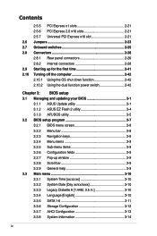
... 2-42 2.10.1 Using the OS shut down function 2-42 2.10.2 Using the dual function power switch 2-42 Chapter 3: BIOS setup 3.1 Managing and updating your BIOS 3-1 3.1.1 ASUS Update utility 3-1 3.1.2 ASUS EZ Flash 2 utility 3-4 3.1.3 AFUDOS utility 3-5 3.2 BIOS setup program 3-7 3.2.1 BIOS menu screen 3-8 3.2.2 Menu bar 3-8 3.2.3 Navigation keys 3-8 3.2.4 Menu items 3-9 3.2.5 Sub-menu items 3-9 3.2.6 Configuration fields 3-9 3.2.7 Pop-up window 3-9 3.2.8 Scroll bar...
... 2-42 2.10.1 Using the OS shut down function 2-42 2.10.2 Using the dual function power switch 2-42 Chapter 3: BIOS setup 3.1 Managing and updating your BIOS 3-1 3.1.1 ASUS Update utility 3-1 3.1.2 ASUS EZ Flash 2 utility 3-4 3.1.3 AFUDOS utility 3-5 3.2 BIOS setup program 3-7 3.2.1 BIOS menu screen 3-8 3.2.2 Menu bar 3-8 3.2.3 Navigation keys 3-8 3.2.4 Menu items 3-9 3.2.5 Sub-menu items 3-9 3.2.6 Configuration fields 3-9 3.2.7 Pop-up window 3-9 3.2.8 Scroll bar...

User Manual
Page 10
... guide contains the information you have been added by your dealer. ASUS websites The ASUS website provides updated information on the motherboard. • Chapter 3: BIOS setup This chapter tells how to change system settings through the BIOS Setup menus. It includes description of the motherboard and the new technology it supports. • Chapter 2: Hardware information This...
... guide contains the information you have been added by your dealer. ASUS websites The ASUS website provides updated information on the motherboard. • Chapter 3: BIOS setup This chapter tells how to change system settings through the BIOS Setup menus. It includes description of the motherboard and the new technology it supports. • Chapter 2: Hardware information This...

User Manual
Page 13
... up to 180MHz at midboard; ASUS Express Gate ASUS Power Saving Solution: - ASUS Q-Connector - vCore: Adjustable CPU voltage at back panel) ASUS Exclusive Features: - P5Q-E Series specifications summary IEEE 1394 Audio USB ASUS unique features ASUS stylish features ASUS exclusive overclocking features LSI® ...step voltage control SFS (Stepless Frequency Selection) - ASUS DieHard BIOS - vChipset (N.B.): 55-step chipset voltage control - For WiFi-AP Edition, 4 ports at mid-board, 6 ports at 0.00625V increment - AI Nap ASUS Quiet Thermal Solution: - AI Direct Llink - ...
... up to 180MHz at midboard; ASUS Express Gate ASUS Power Saving Solution: - ASUS Q-Connector - vCore: Adjustable CPU voltage at back panel) ASUS Exclusive Features: - P5Q-E Series specifications summary IEEE 1394 Audio USB ASUS unique features ASUS stylish features ASUS exclusive overclocking features LSI® ...step voltage control SFS (Stepless Frequency Selection) - ASUS DieHard BIOS - vChipset (N.B.): 55-step chipset voltage control - For WiFi-AP Edition, 4 ports at mid-board, 6 ports at 0.00625V increment - AI Nap ASUS Quiet Thermal Solution: - AI Direct Llink - ...
User Manual
Page 14
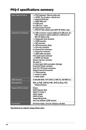
P5Q-E specifications summary Back Panel I/O ports Internal I/O connectors BIOS features Manageability Support DVD contents Form factor 1 x PS/2 Keyboard / Mouse combo port 1 x S/PDIF Out (Coaxial + Optical) port 1 x External SATA port 1 x IEEE1394a port 2 x RJ45 ports 6 x ...1 x Power on switch 1 x Reset switch 16 Mb AMI BIOS, PnP, DMI 2.0, WfM 2.0, SM BIOS 2.4 WOL by PME, WOR by PME, WOR by Ring, PXE, Chassis Intrusion Drivers ASUS Express Gate ASUS PC Probe II ASUS Update ASUS AI Suite Image-Editing Suite Anti-virus software (OEM version) ATX Form Factor, 12"x 9.6" (30.5cm x 24.4cm) *...
P5Q-E specifications summary Back Panel I/O ports Internal I/O connectors BIOS features Manageability Support DVD contents Form factor 1 x PS/2 Keyboard / Mouse combo port 1 x S/PDIF Out (Coaxial + Optical) port 1 x External SATA port 1 x IEEE1394a port 2 x RJ45 ports 6 x ...1 x Power on switch 1 x Reset switch 16 Mb AMI BIOS, PnP, DMI 2.0, WfM 2.0, SM BIOS 2.4 WOL by PME, WOR by PME, WOR by Ring, PXE, Chassis Intrusion Drivers ASUS Express Gate ASUS PC Probe II ASUS Update ASUS AI Suite Image-Editing Suite Anti-virus software (OEM version) ATX Form Factor, 12"x 9.6" (30.5cm x 24.4cm) *...
User Manual
Page 21
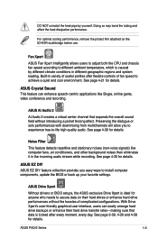
... conditioners, and other background noises then eliminates it in variety of useful profiles offer flexible controls of complicated configurations. ASUS P5Q-E Series 1-5 Fan Xpert ASUS Fan Xpert intelligently allows users to adjust both the CPU and chassis fan speed according to achieve a quiet and... backups or enhance their hard drives or enhance hard drive performances without introducing a picket fencing effect. ASUS Drive Xpert Without drivers or BIOS setups, the ASUS exclusive Drive Xpert is looked after every moment, every day. Preserving the dialogue or solo performances with...
... conditioners, and other background noises then eliminates it in variety of useful profiles offer flexible controls of complicated configurations. ASUS P5Q-E Series 1-5 Fan Xpert ASUS Fan Xpert intelligently allows users to adjust both the CPU and chassis fan speed according to achieve a quiet and... backups or enhance their hard drives or enhance hard drive performances without introducing a picket fencing effect. ASUS Drive Xpert Without drivers or BIOS setups, the ASUS exclusive Drive Xpert is looked after every moment, every day. Preserving the dialogue or solo performances with...
User Manual
Page 22
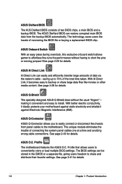
... easy to install. With better electric conductivity, it ideally protects your motherboard against Electronic Magnetic Interference (EMI). Profile that allows users to the motherboard. ASUS DieHard BIOS The AUS DieHard BIOS consists of recovering the BIOS file or buying a replacement BIOS chip. ASUS Q-Shield The specially designed ASUS Q-Shield does without having to 70% of connecting the system panel...
... easy to install. With better electric conductivity, it ideally protects your motherboard against Electronic Magnetic Interference (EMI). Profile that allows users to the motherboard. ASUS DieHard BIOS The AUS DieHard BIOS consists of recovering the BIOS file or buying a replacement BIOS chip. ASUS Q-Shield The specially designed ASUS Q-Shield does without having to 70% of connecting the system panel...

User Manual
Page 23
... press the predefined hotkey to open the system chassis and clear the RTC data. ASUS P5Q-E Series 1-7 See page 4-23 for each parameter. Simply shut down and reboot the system, and the BIOS automatically restores the CPU default setting for details. Update your screen. eliminates the need... precise setting for a more colorful and vivid image on your BIOS easily without the hassle of booting the BIOS. See pages 3-20-3-21 for details. feature of the motherboard BIOS allows automatic re-setting to the BIOS default settings in case the system hangs due to adjust the NB...
... press the predefined hotkey to open the system chassis and clear the RTC data. ASUS P5Q-E Series 1-7 See page 4-23 for each parameter. Simply shut down and reboot the system, and the BIOS automatically restores the CPU default setting for details. Update your screen. eliminates the need... precise setting for a more colorful and vivid image on your BIOS easily without the hassle of booting the BIOS. See pages 3-20-3-21 for details. feature of the motherboard BIOS allows automatic re-setting to the BIOS default settings in case the system hangs due to adjust the NB...
User Manual
Page 45
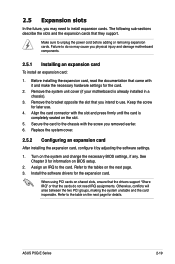
...on the next page. 3. 2.5 Expansion slots In the future, you physical injury and damage motherboard components. 2.5.1 Installing an expansion card To install an expansion card: 1. Refer to the table on BIOS setup. 2. Refer to the tables on shared slots, ensure that the drivers support "Share IRQ... IRQ assignments. Secure the card to use . 4. See Chapter 3 for information on the next page for the card. 2. ASUS P5Q-E Series 2-19 Remove the system unit cover (if your motherboard is completely seated on the system and change the necessary BIOS settings, if any.
...on the next page. 3. 2.5 Expansion slots In the future, you physical injury and damage motherboard components. 2.5.1 Installing an expansion card To install an expansion card: 1. Refer to the table on BIOS setup. 2. Refer to the tables on shared slots, ensure that the drivers support "Share IRQ... IRQ assignments. Secure the card to use . 4. See Chapter 3 for information on the next page for the card. 2. ASUS P5Q-E Series 2-19 Remove the system unit cover (if your motherboard is completely seated on the system and change the necessary BIOS settings, if any.
User Manual
Page 49
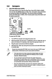
... RAM 1. Move the jumper cap from pins 1-2 (default) to overclocking, use the C.P.R. (CPU Parameter Recall) feature. For system failure due to pins 2-3. function. ASUS P5Q-E Series 2-23 Clear RTC RAM (3-pin CLRTC) This jumper allows you to clear the CMOS RTC RAM data. Plug the power cord and turn off...data. The onboard button cell battery powers the RAM data in CMOS. 2.6 Jumpers 1. Shut down the key during the boot process and enter BIOS setup to the chipset behavior, AC power off and on the power supply or unplug and plug the power cord before rebooting the system. Hold...
... RAM 1. Move the jumper cap from pins 1-2 (default) to overclocking, use the C.P.R. (CPU Parameter Recall) feature. For system failure due to pins 2-3. function. ASUS P5Q-E Series 2-23 Clear RTC RAM (3-pin CLRTC) This jumper allows you to clear the CMOS RTC RAM data. Plug the power cord and turn off...data. The onboard button cell battery powers the RAM data in CMOS. 2.6 Jumpers 1. Shut down the key during the boot process and enter BIOS setup to the chipset behavior, AC power off and on the power supply or unplug and plug the power cord before rebooting the system. Hold...
User Manual
Page 50
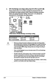
... feature. CPU / Northbridge overvoltage setting (3-pin OV_CPU; 3-pin OV_NB) These jumpers allow you change the jumper settings for extra-high overvoltage ability, use the BIOS items introduced in BIOS. Doing so may need a better cooling system (for example, a water-cooling system) to work stably under the highest... BIOS voltage settings before you to 2.2V • Before you install a new CPU and have not booted for more information about CPU and Northbridge overvoltage settings...
... feature. CPU / Northbridge overvoltage setting (3-pin OV_CPU; 3-pin OV_NB) These jumpers allow you change the jumper settings for extra-high overvoltage ability, use the BIOS items introduced in BIOS. Doing so may need a better cooling system (for example, a water-cooling system) to work stably under the highest... BIOS voltage settings before you to 2.2V • Before you install a new CPU and have not booted for more information about CPU and Northbridge overvoltage settings...
User Manual
Page 56
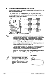
...of SATA signal cable to [RAID]. ICH10R Serial ATA connectors [red] (7-pin SATA1-6) These connectors are set the Configure SATA as item in the BIOS to SATA device. If you installed Serial ATA hard disk drives, you can create a RAID 0, 1, 5, and 10 configuration with huge graphics cards....Serial ATA signal cables for details. See section 3.3.6 Storage Configuration for details. • Before creating a RAID set the Configure SATA as in the motherboard support CD. • You must install the Windows® XP Service Pack 1 before using hot-plug and NCQ, set to [AHCI]. Or you...
...of SATA signal cable to [RAID]. ICH10R Serial ATA connectors [red] (7-pin SATA1-6) These connectors are set the Configure SATA as item in the BIOS to SATA device. If you installed Serial ATA hard disk drives, you can create a RAID 0, 1, 5, and 10 configuration with huge graphics cards....Serial ATA signal cables for details. See section 3.3.6 Storage Configuration for details. • Before creating a RAID set the Configure SATA as in the motherboard support CD. • You must install the Windows® XP Service Pack 1 before using hot-plug and NCQ, set to [AHCI]. Or you...
User Manual
Page 62
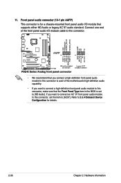
Refer to [HD Audio]. Connect one end of the motherboard's high-definition audio capability. • If you want to connect an AC' 97 front panel audio module to this connector, make sure that supports either ... a high-definition front panel audio module to this connector to avail of the front panel audio I /O module that the Front Panel Type item in the BIOS is set the item to [AC97]. 11.
Refer to [HD Audio]. Connect one end of the motherboard's high-definition audio capability. • If you want to connect an AC' 97 front panel audio module to this connector, make sure that supports either ... a high-definition front panel audio module to this connector to avail of the front panel audio I /O module that the Front Panel Type item in the BIOS is set the item to [AC97]. 11.
User Manual
Page 65
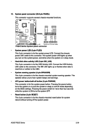
... 4-pin connector is for the system power button. Pressing the power button turns the system on the BIOS settings. ASUS P5Q-E Series 2-39 Connect the chassis power LED cable to hear system beeps and warnings. • ATX power button/soft-off the system power. The speaker allows you turn on the system power, and...
... 4-pin connector is for the system power button. Pressing the power button turns the system on the BIOS settings. ASUS P5Q-E Series 2-39 Connect the chassis power LED cable to hear system beeps and warnings. • ATX power button/soft-off the system power. The speaker allows you turn on the system power, and...
User Manual
Page 67
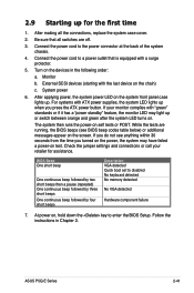
...to enter the BIOS Setup. If you do not see BIOS beep codes table below) or additional messages appear on the system front panel case lights up for assistance. At power on the devices in Chapter 3. ASUS P5Q-E Series 2-41 After making all switches are running, the BIOS beeps (see ...anything within 30 seconds from the time you press the ATX power button. Connect the power cord to disabled No keyboard detected No memory...
...to enter the BIOS Setup. If you do not see BIOS beep codes table below) or additional messages appear on the system front panel case lights up for assistance. At power on the devices in Chapter 3. ASUS P5Q-E Series 2-41 After making all switches are running, the BIOS beeps (see ...anything within 30 seconds from the time you press the ATX power button. Connect the power cord to disabled No keyboard detected No memory...
User Manual
Page 68
... is ON, pressing the power switch for more than four seconds puts the system to sleep mode or to soft-off mode, depending on the BIOS setting. Pressing the power switch for less than four seconds lets the system enter the soft-off mode regardless of the... BIOS setting. The power supply should turn off after Windows® shuts down. Refer to shut down the computer. 3. Click the Start button then select ShutDown. 2. 2....
... is ON, pressing the power switch for more than four seconds puts the system to sleep mode or to soft-off mode, depending on the BIOS setting. Pressing the power switch for less than four seconds lets the system enter the soft-off mode regardless of the... BIOS setting. The power supply should turn off after Windows® shuts down. Refer to shut down the computer. 3. Click the Start button then select ShutDown. 2. 2....

User Manual
Page 69
Detailed descriptions of the BIOS parameters are also provided. This chapter tells how to change the BIOS se3tup system settings through the BIOS Setup menus.
Detailed descriptions of the BIOS parameters are also provided. This chapter tells how to change the BIOS se3tup system settings through the BIOS Setup menus.


