User Manual
Page 29
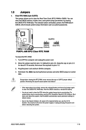
Hold down and reboot the system, then the BIOS automatically resets parameter settings to default values. • Due to the chipset limitation, AC power off and on CLRTC jumper default position. ASUS P5KPL-AM EPU 1-19 To erase the RTC RAM: 1. Except when clearing the RTC RAM, never remove the cap on the ... (RTC) RAM in CMOS, which include system setup information such as system passwords. Shut down the key during the boot process and enter BIOS setup to clear the CMOS RTC RAM data. function. The onboard button cell battery powers the RAM data in CMOS. Move the jumper cap...
Hold down and reboot the system, then the BIOS automatically resets parameter settings to default values. • Due to the chipset limitation, AC power off and on CLRTC jumper default position. ASUS P5KPL-AM EPU 1-19 To erase the RTC RAM: 1. Except when clearing the RTC RAM, never remove the cap on the ... (RTC) RAM in CMOS, which include system setup information such as system passwords. Shut down the key during the boot process and enter BIOS setup to clear the CMOS RTC RAM data. function. The onboard button cell battery powers the RAM data in CMOS. Move the jumper cap...
User Manual
Page 36
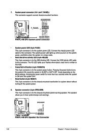
...Pressing the power switch for more than four seconds while the system is ON turns the system OFF. • Reset button (2-pin RESET) This 2-pin connector is for the chassis-mounted reset button for the system power LED. Connect the HDD Activity LED cable to this connector. Connect the chassis power ...pin connector is read from or written to hear system beeps and warnings. 1-26 Chapter 1: Product introduction The speaker allows you turn on the BIOS settings. The system power LED lights up or flashes when data is for the system power button. Pressing the power button turns the system ...
...Pressing the power switch for more than four seconds while the system is ON turns the system OFF. • Reset button (2-pin RESET) This 2-pin connector is for the chassis-mounted reset button for the system power LED. Connect the HDD Activity LED cable to this connector. Connect the chassis power ...pin connector is read from or written to hear system beeps and warnings. 1-26 Chapter 1: Product introduction The speaker allows you turn on the BIOS settings. The system power LED lights up or flashes when data is for the system power button. Pressing the power button turns the system ...
User Manual
Page 41
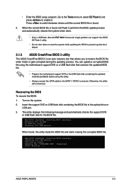
... for CD-ROM... Checking for the BIOS file. You can support the ASUS EZ Flash 2 utility. • Do not shut down or reset the system while updating the BIOS to prevent system boot failure! 2.1.3 ASUS CrashFree BIOS 3 utility The ASUS CrashFree BIOS 3 is an auto recovery tool that...correct BIOS file is found , the utility reads the BIOS file and starts erasing the corrupted BIOS file. USB Device found ! Start Erasing...\ ASUS P5KPL-AM EPU 2-3 Turn on the system. 2. Starting BIOS recovery... CD-ROM not found . Bad BIOS checksum. When found , EZ Flash 2 performs the BIOS ...
... for CD-ROM... Checking for the BIOS file. You can support the ASUS EZ Flash 2 utility. • Do not shut down or reset the system while updating the BIOS to prevent system boot failure! 2.1.3 ASUS CrashFree BIOS 3 utility The ASUS CrashFree BIOS 3 is an auto recovery tool that...correct BIOS file is found , the utility reads the BIOS file and starts erasing the corrupted BIOS file. USB Device found ! Start Erasing...\ ASUS P5KPL-AM EPU 2-3 Turn on the system. 2. Starting BIOS recovery... CD-ROM not found . Bad BIOS checksum. When found , EZ Flash 2 performs the BIOS ...
User Manual
Page 42
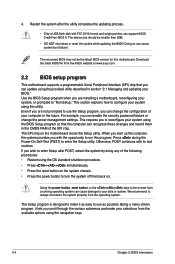
... computer in section "2.1 Managing and updating your system using the OS standard shutdown procedure. • Press ++ simultaneously. • Press the reset button on the system chassis. • Press the power button to enter the Setup utility. We recommend to use as easy to your ...selections from the ASUS website at www.asus.com. 2.2 BIOS setup program This motherboard supports a programmable Serial Peripheral Interface (SPI) chip that the computer can enable the security password ...
... computer in section "2.1 Managing and updating your system using the OS standard shutdown procedure. • Press ++ simultaneously. • Press the reset button on the system chassis. • Press the power button to enter the Setup utility. We recommend to use as easy to your ...selections from the ASUS website at www.asus.com. 2.2 BIOS setup program This motherboard supports a programmable Serial Peripheral Interface (SPI) chip that the computer can enable the security password ...
User Manual
Page 52
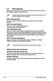
... storage device is enabled. The Module Version and USB Devices Enabled items show the auto-detected values. USB Mass Storage Device Configuration USB Mass Storage Reset Delay [20 Sec] Allows you to initialize. Configuration options: [10 Sec] [20 Sec] [30 Sec] [40 Sec] Emulation Type [Auto] ...Allows you to set the maximum time that the BIOS waits for Legacy USB storage devices, including USB flash drives and USB hard drives. Configuration options: [Auto] [Floppy] [Forced FDD] [Hard Disk] [CDROM]...
... storage device is enabled. The Module Version and USB Devices Enabled items show the auto-detected values. USB Mass Storage Device Configuration USB Mass Storage Reset Delay [20 Sec] Allows you to initialize. Configuration options: [10 Sec] [20 Sec] [30 Sec] [40 Sec] Emulation Type [Auto] ...Allows you to set the maximum time that the BIOS waits for Legacy USB storage devices, including USB flash drives and USB hard drives. Configuration options: [Auto] [Floppy] [Forced FDD] [Hard Disk] [CDROM]...


