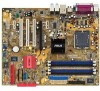
P5GD1 User's Manual English Version E1745
Page 15
... installing the motherboard, and hardware devices on it another standout in your package with the list below. 1.2 Package contents Check your retailer. ASUS P5GD1 1-1 Before you for the following items. Motherboard ASUS P5GD1 motherboard I/O modules USB 2.0 (2 ports) and GAME (1 port) module Cables 2 x Serial ATA signal cables 1 x Serial ATA power cables 1 x Ultra DMA/133 cables...
P5GD1 User's Manual English Version E1745
Page 17
... USB 1.1. See pages 2-24 and 2-25 for details. 8-channel high definition audio The motherboard supports 8-channel High Definition Audio through the S/PDIF interfaces on USB 2.0. ASUS P5GD1 1-3 The S/PDIF technology turns your computer into a high-end entertainment system with 24-bit DAC, a stereo 16-bit ADC, and an AC97 2.3 compatible multi-channel...
P5GD1 User's Manual English Version E1745
Page 20
Chapter summary 2.1 Before you proceed 2-1 2.2 Motherboard overview 2-2 2.3 Central Processing Unit (CPU 2-6 2.4 System memory 2-11 2.5 Expansion slots 2-15 2.6 Jumpers 2-18 2.7 Connectors 2-21 ASUS P5GD1
P5GD1 User's Manual English Version E1745
Page 21
... it on a grounded antistatic pad or in the bag that came with a standby power LED that lights up to the motherboard, peripherals, and/or components. P5GD1 P5GD1 Onboard LED SB_PWR ON Standby Power OFF Powered Off ASUS P5GD1 2-1 2.1 Before you proceed Take note of the onboard LED.
P5GD1 User's Manual English Version E1745
Page 23
... surround L/R Below: Bass Top:Line In Center:Line Out Below:Mic In Marvell 88E8053 USBPW12 USBPW34 PWR_FAN PCIEX1_1 Intel R 915-P MCH CPU_FAN PCIEX16 PCI1 CD P5GD1 PCI2 ALC861 SPDIF_OUT PCI3 AAFP PCIEX1_2 PCIEX1_3 R Intel ICH6R COM2 CR2032 3V Lithium Cell CMOS Power SATA2 SATA4 SATA1 PRI_RAID SATA3 ITE 8212F USB56 USBPW56...
P5GD1 User's Manual English Version E1745
Page 25
.... Internal connectors 1. Reset switch (Blue 2-pin RESET) Page 2-23 2-23 2-24 2-24 2-25 2-26 2-26 2-26 2-27 2-27 2-28 2-28 2-29 2-29 2-30 2-30 2-31 ASUS P5GD1 2-5 Optical audio connector (4-pin CD) 14. Power fan connector (3-pin PWR_FAN) 8. ATX 12V power connector (4-pin ATX12V) 13. System warning speaker (Orange 4-pin SPEAKER) - Chassis...
P5GD1 User's Manual English Version E1745
Page 27
... thumb (A) and move it is on the bottom-left corner of the arrow to the left (B) until it to a 135º angle. 4. Gold triangle mark ASUS P5GD1 A 2-7 Lift the load lever in the direction of the socket. The socket alignment key should face you are installing a CPU. 3. Position the CPU over the...
P5GD1 User's Manual English Version E1745
Page 29
If you purchased a separate CPU heatsink and fan assembly, make sure that the four pins match the holes on the motherboard. Push pin Motherboard hole ASUS P5GD1 2-9 Place the heatsink on top of the installed CPU, making sure that you use only Intel®-certified multi-directional heatsink and fan. • Your ...
P5GD1 User's Manual English Version E1745
Page 31
... Double Data Rate (DDR) Dual Inline Memory Modules (DIMM) sockets. The following figure illustrates the location of the recommended configurations in this motherboard. ASUS P5GD1 2-11 Use any of the sockets: DIMM_A1 DIMM_A2 DIMM_B1 DIMM_B2 P5GD1 P5GD1 184-Pin DDR DIMM Sockets 2.4.2 Memory Configurations You may cause memory sizing error or system boot failure.
P5GD1 User's Manual English Version E1745
Page 33
...; ••• •• • • ••• •• ••• •• ••• •• Legend: A - C - Double-sided ASUS P5GD1 2-13 supports on pair of modules inserted into the blue and black slots as one module inserted into either slot, in a Single-channel memory configuration...
P5GD1 User's Manual English Version E1745
Page 35
... that they support. Remove the system unit cover (if your motherboard is completely seated on the system and change the necessary BIOS settings, if any. ASUS P5GD1 2-15 Secure the card to the chassis with the screw you intend to use . 4. Failure to do so may cause you may need to the...
P5GD1 User's Manual English Version E1745
Page 37
.... 2.5.4 PCI slots The PCI slots support cards such as a LAN card, SCSI card, USB card, and other cards that comply with the PCI Express specifications. ASUS P5GD1 2-17 The figure shows a network card installed on the PCI Express x16 slot. 2.5.6 PCI Express x1 slot This motherboard supports PCI Express x1 network cards...
P5GD1 User's Manual English Version E1745
Page 39
... the rear USB ports. The USBPWR12 and USBPWR34 jumpers are for each USB port; USBPW12 USBPW34 12 23 +5V (Default) +5VSB USBPW56 P5GD1 USBPW78 12 23 P5GD1 USB device wake-up +5V (Default) +5VSB • The USB device wake-up . • The total current consumed must NOT ...exceed the power supply capability (+5VSB) whether under normal condition or in reduced power mode). ASUS P5GD1 2-19 2 . The USBPWR56 and USBPWR78 jumper is for the internal USB connectors that can connect to CPU, DRAM in slow refresh, power supply...
P5GD1 User's Manual English Version E1745
Page 41
... connection ORANGE GREEN 100 Mbps connection 1 Gbps connection ACT/LINK SPEED LED LED LAN port 4 . R e a r S p e a k e r O u t p o r t ( g r a y ) . This port connects a tape, CD, DVD player, or other devices. 3 . ASUS P5GD1 2-21 Refer to a Local Area Network (LAN) through a network hub. S i d e S p e a k e r O u t p o r t ( b l a c k ) . This port connects the side speakers in an 8-channel audio configuration. 6 . This port connects a microphone...
P5GD1 User's Manual English Version E1745
Page 43
P5GD1 P5GD1 IDE connector PIN 1 ASUS P5GD1 2-23 Floppy disk drive connector (34-1 pin FLOPPY) This connector is for the provided floppy disk drive (FDD) signal cable. P5GD1 PIN 1 P5GD1 Floppy disk drive connector 2 . 2.7.2 Internal connectors 1 . Primary IDE connector (40-1 pin PRI_IDE) This connector is for an Ultra DMA 100/66 signal cable. This prevents ...
P5GD1 User's Manual English Version E1745
Page 45
...to support S3 function. Serial ATA Master/Slave connectors Connector SATA1, SATA2 SATA3, SATA4 Setting Master Slave Use Boot disk Data disk ASUS P5GD1 2-25 4. If you installed Serial ATA hard disk drives, you are for the Serial ATA signal cables for information on creating ...a RAID configuration. Refer to Chapter 5 for Serial ATA hard disk drives. P5GD1 P5GD1 SATA connectors SATA2 GND RSATA_TXP2 RSATA_TXN2 GND RSATA_RXN2 RSATA_RXP2 GND SATA1 GND RSATA_TXP1 RSATA_TXN1 GND RSATA_RXN1 RSATA_RXP1 GND SATA4 GND RSATA_TXP4 ...
P5GD1 User's Manual English Version E1745
Page 47
... to the USB connectors. USB+5V USB_P8USB_P8+ GND NC USB+5V USB_P6USB_P6+ GND NC P5GD1 P5GD1 USB 2.0 connectors USB56 1 USB78 1 USB+5V USB_P7USB_P7+ GND USB+5V USB_P5USB_P5+ GND Never connect a 1 3 9 4 c a b l e to 480 Mbps connection speed. ASUS P5GD1 2-27 USB connectors (10-1 pin USB56, USB78) These connectors are for a serial ...module cable to this connector, then install the module to a slot opening at the back of the system chassis. COM2 P5GD1 PIN 1 P5GD1 Serial port connectors 7 . Serial port connector (10-1 pin COM2) This connector is for USB 2.0 ports.
P5GD1 User's Manual English Version E1745
Page 49
The GAME/MIDI port connects a joystick or game pad for playing games, and MIDI devices for a GAME/MIDI port. P5GD1 CD P5GD1 CD audio connector 10. GAME/MIDI port connector (16-1 pin GAME) This connector is for the 4-pin audio cable that connects to a slot opening at ... connector (4-pin CD) This connector is for playing or editing audio files. +5V J2B1 J2CX MIDI_OUT J2CY J2B2 MIDI_IN P5GD1 P5GD1 GAME connector GAME +5V J1B1 J1CX GND GND J1CY J1B2 +5V ASUS P5GD1 2-29 Connect the USB/GAME module cable to this connector, then install the module to the audio connector at the...
P5GD1 User's Manual English Version E1745
Page 51
Connect the chassis power LED cable to this connector. ASUS P5GD1 2-31 PWR Ground Reset Ground IDE_LED P5GD1 System Panel Connector RESET PWRSW The sytem panel connector is for easy connection. Connect the HDD Activity LED cable to the connector description below for ...; Hard disk drive activity (Red 2-pin IDE_LED) This 2-pin connector is for the HDD Activity LED. PLED SPEAKER PLED+ PLED+5V Ground Ground Speaker PANEL P5GD1 IDE_LED+ IDE_LED- Refer to this connector. The system power LED lights up or flashes when data is read from or written to hear system beeps...
P5GD1 User's Manual English Version E1745
Page 54
Chapter summary 3.1 Starting up for the first time 3-1 3.2 Powering off the computer 3-2 ASUS P5GD1