
Motherboard DIY Troubleshooting Guide
Page 45
F1 : Help ↑↓ : Select Item -/+ : Change Value F5 : Setup Defaults ESC : Exit →← : Select Menu Enter : Select Sub-menu F10 : Save and Exit 2-13 IDE Primary Master IDE Auto-Detection IDE Primary Master Access Mode Capacity Cylinder Head Sector Transfer Mode [Press Enter] [Manual] [CHS] 40020 MB [19158] [ 16] [ 255] UDMA 2 Select Menu Item Specific Help Enter the value.
F1 : Help ↑↓ : Select Item -/+ : Change Value F5 : Setup Defaults ESC : Exit →← : Select Menu Enter : Select Sub-menu F10 : Save and Exit 2-13 IDE Primary Master IDE Auto-Detection IDE Primary Master Access Mode Capacity Cylinder Head Sector Transfer Mode [Press Enter] [Manual] [CHS] 40020 MB [19158] [ 16] [ 255] UDMA 2 Select Menu Item Specific Help Enter the value.

Motherboard DIY Troubleshooting Guide
Page 48
Frequency/Voltage Control CPU Clock Ratio CPU/MEM Clock Selectable x CPU Clock Setting x MEM Clock Setting Spread Spectrum [17 X] [Auto] [100] [DDR266] [+/- 0.7%] Select Menu Item Specific Help Sets the ratio between CPU core clock and the FSB frequency. F1 : Help ↑↓ : Select Item -/+ : Change Value F5 : Setup Defaults ESC : Exit →← : Select Menu Enter : Select Sub-menu F10 : Save and Exit 2-16
Frequency/Voltage Control CPU Clock Ratio CPU/MEM Clock Selectable x CPU Clock Setting x MEM Clock Setting Spread Spectrum [17 X] [Auto] [100] [DDR266] [+/- 0.7%] Select Menu Item Specific Help Sets the ratio between CPU core clock and the FSB frequency. F1 : Help ↑↓ : Select Item -/+ : Change Value F5 : Setup Defaults ESC : Exit →← : Select Menu Enter : Select Sub-menu F10 : Save and Exit 2-16

Motherboard DIY Troubleshooting Guide
Page 49
... Performance Acceleration Dynamic Clock Gating [Auto (By SPD)] 2.5 [Auto (By SPD)] 3T 6T 3T [128MB] [2T] [Enabled] [Enabled] 8X [Disabled] [Auto] [Enabled] Select Menu Item Specific Help Set the latency between the DRAM command and the time the data actually becomes available.
... Performance Acceleration Dynamic Clock Gating [Auto (By SPD)] 2.5 [Auto (By SPD)] 3T 6T 3T [128MB] [2T] [Enabled] [Enabled] 8X [Disabled] [Auto] [Enabled] Select Menu Item Specific Help Set the latency between the DRAM command and the time the data actually becomes available.

Motherboard DIY Troubleshooting Guide
Page 51
F1 : Help ↑↓ : Select Item -/+ : Change Value F5 : Setup Defaults ESC : Exit →← : Select Menu Enter : Select Sub-menu F10 : Save and Exit 2-19 I/O Device Configuration Onboard Serial Port 1 Onboard Parallel Port Parallel Port Mode x ECP Mode USE DMA EPP Mode Select Onboard AC97 Audio Onboard LAN Game Port Address MIDI Port Address MIDI Port IRQ [3F8/IRQ4] [378/IRQ7] [SPP] 3 [EPP1.7] [Enabled] [Enabled] [201] [330] [5] Select Menu Item Specific Help Press [Enter] to select the I/O address & IRQ for COM1.
F1 : Help ↑↓ : Select Item -/+ : Change Value F5 : Setup Defaults ESC : Exit →← : Select Menu Enter : Select Sub-menu F10 : Save and Exit 2-19 I/O Device Configuration Onboard Serial Port 1 Onboard Parallel Port Parallel Port Mode x ECP Mode USE DMA EPP Mode Select Onboard AC97 Audio Onboard LAN Game Port Address MIDI Port Address MIDI Port IRQ [3F8/IRQ4] [378/IRQ7] [SPP] 3 [EPP1.7] [Enabled] [Enabled] [201] [330] [5] Select Menu Item Specific Help Press [Enter] to select the I/O address & IRQ for COM1.

Motherboard DIY Troubleshooting Guide
Page 52
PCI Configuration Onboard LAN Boot ROM [Disabled] Resources Controlled By [Auto (ESCD)] x IRQ Resources PCI/CGA Palette Snoop Assign IRQ for VGA Assign IRQ for USB PCI Latency Timer (CLK) PCI IRQ Actived By [Disabled] [Enabled] [Enabled] [ 64] [Level] Select Menu Item Specific Help Enable/Disable the onboard SATA. F1 : Help ↑↓ : Select Item -/+ : Change Value F5 : Setup Defaults ESC : Exit →← : Select Menu Enter : Select Sub-menu F10 : Save and Exit 2-20
PCI Configuration Onboard LAN Boot ROM [Disabled] Resources Controlled By [Auto (ESCD)] x IRQ Resources PCI/CGA Palette Snoop Assign IRQ for VGA Assign IRQ for USB PCI Latency Timer (CLK) PCI IRQ Actived By [Disabled] [Enabled] [Enabled] [ 64] [Level] Select Menu Item Specific Help Enable/Disable the onboard SATA. F1 : Help ↑↓ : Select Item -/+ : Change Value F5 : Setup Defaults ESC : Exit →← : Select Menu Enter : Select Sub-menu F10 : Save and Exit 2-20

Motherboard DIY Troubleshooting Guide
Page 53
...] [PCI Device] [PCI Device] [PCI Device] [PCI Device] [PCI Device] [PCI Device] [PCI Device] [PCI Device] Select Menu Item Specific Help Legacy ISA for devices compliant with the original PC AT bus specification, PCI/ISA PnP for devices compliant with the Plug and Play standard whether designed for PCI or ISA bus...
...] [PCI Device] [PCI Device] [PCI Device] [PCI Device] [PCI Device] [PCI Device] [PCI Device] [PCI Device] Select Menu Item Specific Help Legacy ISA for devices compliant with the original PC AT bus specification, PCI/ISA PnP for devices compliant with the Plug and Play standard whether designed for PCI or ISA bus...

Motherboard DIY Troubleshooting Guide
Page 54
F1 : Help ↑↓ : Select Item -/+ : Change Value F5 : Setup Defaults ESC : Exit →← : Select Menu Enter : Select Sub-menu F10 : Save and Exit 2-22 ACPI Suspend Type Suspend Mode AC Power Loss Restart Power Up Control Hardware Monitor [S1&S3] [Disabled] [Disabled] Select Menu Item Specific Help Select the ACPI state used for System Suspend.
F1 : Help ↑↓ : Select Item -/+ : Change Value F5 : Setup Defaults ESC : Exit →← : Select Menu Enter : Select Sub-menu F10 : Save and Exit 2-22 ACPI Suspend Type Suspend Mode AC Power Loss Restart Power Up Control Hardware Monitor [S1&S3] [Disabled] [Disabled] Select Menu Item Specific Help Select the ACPI state used for System Suspend.

Motherboard DIY Troubleshooting Guide
Page 55
Power Up Control Power Up On PCI Devices [Disabled] Power Up By PS/2 Keyboard [Disabled] Power Up By PS/2 Mouse [Disabled] Power Up by Onboard LAN [Disabled] RTC Alarm Resume [Disabled] x Date (of Month) 0 x Resume Time (hh:mm:ss) 0 : 0 : 0 PWR Button
Power Up Control Power Up On PCI Devices [Disabled] Power Up By PS/2 Keyboard [Disabled] Power Up By PS/2 Mouse [Disabled] Power Up by Onboard LAN [Disabled] RTC Alarm Resume [Disabled] x Date (of Month) 0 x Resume Time (hh:mm:ss) 0 : 0 : 0 PWR Button

Motherboard DIY Troubleshooting Guide
Page 57
Hardware Monitor CPU Temperature MB Temperature 47° C 45° C CPU Fan Speed Chassis Fan Speed 5443RPM 0RPM VCore + 3.3V + 5V + 12V 1.79V 3.37V 4.94V 11.36V Select Menu Item Specific Help Press [Enter] to enable or disable. F1 : Help ↑↓ : Select Item -/+ : Change Value F5 : Setup Defaults ESC : Exit →← : Select Menu Enter : Select Sub-menu F10 : Save and Exit 2-25
Hardware Monitor CPU Temperature MB Temperature 47° C 45° C CPU Fan Speed Chassis Fan Speed 5443RPM 0RPM VCore + 3.3V + 5V + 12V 1.79V 3.37V 4.94V 11.36V Select Menu Item Specific Help Press [Enter] to enable or disable. F1 : Help ↑↓ : Select Item -/+ : Change Value F5 : Setup Defaults ESC : Exit →← : Select Menu Enter : Select Sub-menu F10 : Save and Exit 2-25

Motherboard DIY Troubleshooting Guide
Page 58
F1 : Help ↑↓ : Select Item -/+ : Change Value F5 : Setup Defaults ESC : Exit →← : Select Menu Enter : Select Sub-menu F10 : Save and Exit 2-26 First Boot Device Second Boot Device Third Boot Device Fourth Boot Device Plug & Play OS Reset Configuration Data Quick Power On Self Test Boot Up Floppy Seek Boot Up NumLock Status APIC Mode [HDD-0] [CDROM] [Floppy] [Disabled] [Yes] [Disabled] [Enabled] [Disabled] [On] [Enabled] Select Menu Item Specific Help Select your boot device priority.
F1 : Help ↑↓ : Select Item -/+ : Change Value F5 : Setup Defaults ESC : Exit →← : Select Menu Enter : Select Sub-menu F10 : Save and Exit 2-26 First Boot Device Second Boot Device Third Boot Device Fourth Boot Device Plug & Play OS Reset Configuration Data Quick Power On Self Test Boot Up Floppy Seek Boot Up NumLock Status APIC Mode [HDD-0] [CDROM] [Floppy] [Disabled] [Yes] [Disabled] [Enabled] [Disabled] [On] [Enabled] Select Menu Item Specific Help Select your boot device priority.

Motherboard DIY Troubleshooting Guide
Page 60
F1 : Help ↑↓ : Select Item -/+ : Change Value F5 : Setup Defaults ESC : Exit →← : Select Menu Enter : Select Sub-menu F10 : Save and Exit 2-28 Save & Exit Exit Without Saving Load SETUP Defaults Discard Changes Save Changes Select Menu Item Specific Help This option saves data to CMOS and exits the BIOS Setup.
F1 : Help ↑↓ : Select Item -/+ : Change Value F5 : Setup Defaults ESC : Exit →← : Select Menu Enter : Select Sub-menu F10 : Save and Exit 2-28 Save & Exit Exit Without Saving Load SETUP Defaults Discard Changes Save Changes Select Menu Item Specific Help This option saves data to CMOS and exits the BIOS Setup.

P4U800-X user's manual for English Version
Page 2
... FROM ANY DEFECT OR ERROR IN THIS MANUAL OR PRODUCT. ASUS ASSUMES NO RESPONSIBILITY OR LIABILITY FOR ANY ERRORS OR INACCURACIES THAT MAY APPEAR IN THIS MANUAL, INCLUDING THE PRODUCTS AND SOFTWARE DESCRIBED IN IT. SPECIFICATIONS AND INFORMATION CONTAINED IN THIS MANUAL ARE FURNISHED FOR INFORMATIONAL USE... ONLY, AND ARE SUBJECT TO CHANGE AT ANY TIME WITHOUT NOTICE, AND SHOULD NOT BE CONSTRUED AS A COMMITMENT BY ASUS. No part of this manual may or may...
... FROM ANY DEFECT OR ERROR IN THIS MANUAL OR PRODUCT. ASUS ASSUMES NO RESPONSIBILITY OR LIABILITY FOR ANY ERRORS OR INACCURACIES THAT MAY APPEAR IN THIS MANUAL, INCLUDING THE PRODUCTS AND SOFTWARE DESCRIBED IN IT. SPECIFICATIONS AND INFORMATION CONTAINED IN THIS MANUAL ARE FURNISHED FOR INFORMATIONAL USE... ONLY, AND ARE SUBJECT TO CHANGE AT ANY TIME WITHOUT NOTICE, AND SHOULD NOT BE CONSTRUED AS A COMMITMENT BY ASUS. No part of this manual may or may...

P4U800-X user's manual for English Version
Page 3
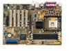
Features Contents Notices v Safety information vi About this guide vii Conventions used in this guide vii Where to find more information vii P4U800-X specification summary viii Chapter 1: Product introduction 1.1 Welcome 1-2 1.2 Package contents 1-2 1.3 Special features 1-2 1.4 Before you proceed 1-4 1.5 Motherboard overview 1-5 1.5.1 Motherboard layout 1-5 1.5.2 Placement direction 1-6 1.5.3 Screw holes 1-6 1.6 Central Processing Unit (CPU 1-7 1.6.1 ...
Features Contents Notices v Safety information vi About this guide vii Conventions used in this guide vii Where to find more information vii P4U800-X specification summary viii Chapter 1: Product introduction 1.1 Welcome 1-2 1.2 Package contents 1-2 1.3 Special features 1-2 1.4 Before you proceed 1-4 1.5 Motherboard overview 1-5 1.5.1 Motherboard layout 1-5 1.5.2 Placement direction 1-6 1.5.3 Screw holes 1-6 1.6 Central Processing Unit (CPU 1-7 1.6.1 ...

P4U800-X user's manual for English Version
Page 8
P4U800-X specification summary CPU Chipset Front Side Bus (FSB) Memory Expansion slots Storage Audio LAN Special features Overclocking Rear panel I/O Socket 478 for Intel® Pentium® 4 / ... CODEC support S/PDIF out interface ULI M1563 integrated 10/100 Mbps MAC with VIA VT6103 PHY ASUS EZ Flash ASUS C.P.R. (CPU Parameter Recall) ASUS CrashFree BIOS ASUS JumperFree SFS (Stepless Frequency Selection) at 1Mhz increment Adjustable FSB/DDR ratio ASUS C.P.R. (CPU Parameter Recall) 1 x Parallel port 1 x Serial port 1 x PS/2 keyboard port 1 x PS/2 mouse port 4 x USB 2.0 ports...
P4U800-X specification summary CPU Chipset Front Side Bus (FSB) Memory Expansion slots Storage Audio LAN Special features Overclocking Rear panel I/O Socket 478 for Intel® Pentium® 4 / ... CODEC support S/PDIF out interface ULI M1563 integrated 10/100 Mbps MAC with VIA VT6103 PHY ASUS EZ Flash ASUS C.P.R. (CPU Parameter Recall) ASUS CrashFree BIOS ASUS JumperFree SFS (Stepless Frequency Selection) at 1Mhz increment Adjustable FSB/DDR ratio ASUS C.P.R. (CPU Parameter Recall) 1 x Parallel port 1 x Serial port 1 x PS/2 keyboard port 1 x PS/2 mouse port 4 x USB 2.0 ports...

P4U800-X user's manual for English Version
Page 9
ix P4U800-X specification summary Internal I/O BIOS features Industry standard Manageability Power Requirement Form Factor Support CD contents 1 x USB 2.0 connector for 2 additional USB ports CPU/Chassis fan connectors 20-..., ACPI, PnP, DMI2.0, WfM 2.0, SM BIOS 2.3, DMI 2.0, ASUS CrashFree BIOS, ASUS EZ Flash PCI 2.2, USB 2.0/1.1 DMI 2.0, WOL/WOR by PME, SMBus ATX power supply (with 4-pin 12V plug) ATX form factor: 12 in x 8.6 in (30.5 cm x 20.8 cm) Device drivers ASUS PC Probe ASUS LiveUpdate Anti-virus utility * Specifications are subject to change without notice.
ix P4U800-X specification summary Internal I/O BIOS features Industry standard Manageability Power Requirement Form Factor Support CD contents 1 x USB 2.0 connector for 2 additional USB ports CPU/Chassis fan connectors 20-..., ACPI, PnP, DMI2.0, WfM 2.0, SM BIOS 2.3, DMI 2.0, ASUS CrashFree BIOS, ASUS EZ Flash PCI 2.2, USB 2.0/1.1 DMI 2.0, WOL/WOR by PME, SMBus ATX power supply (with 4-pin 12V plug) ATX form factor: 12 in x 8.6 in (30.5 cm x 20.8 cm) Device drivers ASUS PC Probe ASUS LiveUpdate Anti-virus utility * Specifications are subject to change without notice.
P4U800-X user's manual for English Version
Page 13
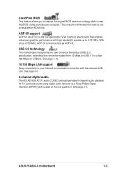
USB 2.0 technology The motherboard implements the new Universal Serial Bus (USB) 2.0 specification, extending the connection speed from a floppy disk in case the BIOS codes and data are corrupted. See page 3-3. CrashFree BIOS This feature allows you to ... a fast 480 Mbps on USB 2.0. AGP 8X support AGP 8X (AGP 3.0) is twice as fast as AGP 4X. ASUS P4U800-X motherboard 1-3 With a bus of 533Mhz, AGP 8X is the next generation VGA interface specification that enables enhanced graphics performance with the onboard LAN port. See page 1-15. 10/100 Mbps LAN support Easy...
USB 2.0 technology The motherboard implements the new Universal Serial Bus (USB) 2.0 specification, extending the connection speed from a floppy disk in case the BIOS codes and data are corrupted. See page 3-3. CrashFree BIOS This feature allows you to ... a fast 480 Mbps on USB 2.0. AGP 8X support AGP 8X (AGP 3.0) is twice as fast as AGP 4X. ASUS P4U800-X motherboard 1-3 With a bus of 533Mhz, AGP 8X is the next generation VGA interface specification that enables enhanced graphics performance with the onboard LAN port. See page 1-15. 10/100 Mbps LAN support Easy...

P4U800-X user's manual for English Version
Page 17
... XP™ Service Pack 1. 6. Power up the system and enter the BIOS setup (See Chapter 2: BIOS Information). P4U800-X Gold Arrow ® P4U800-X Socket 478 Incorrect installation of the CPU socket. It is supported under Windows® XP™ and later versions only.... 3. ASUS P4U800-X motherboard 1-7 This motherboard supports Intel® Pentium® 4 CPUs with Hyper-Threading Technology. 2. Make sure to the Windows OS System Properties -> Hardware -> Device Manager -> Processors. Notes on one corner. Reboot the computer. The list should match a specific corner of...
... XP™ Service Pack 1. 6. Power up the system and enter the BIOS setup (See Chapter 2: BIOS Information). P4U800-X Gold Arrow ® P4U800-X Socket 478 Incorrect installation of the CPU socket. It is supported under Windows® XP™ and later versions only.... 3. ASUS P4U800-X motherboard 1-7 This motherboard supports Intel® Pentium® 4 CPUs with Hyper-Threading Technology. 2. Make sure to the Windows OS System Properties -> Hardware -> Device Manager -> Processors. Notes on one corner. Reboot the computer. The list should match a specific corner of...

P4U800-X user's manual for English Version
Page 22
... performance and overclocking stability. 1-12 Chapter 1: Product introduction P4U800-X Keyed for 1.5v ® P4U800-X Accelerated Graphics Port (AGP) If installing the ATI 9500 or 9700 Pro Series VGA cards, use only the card version PN xxx-xxxxx-30 or later, for one with PCI specifications. 1.8.4 AGP slot The Accelerated Graphics Port (AGP) slot... AGP cards. 1.8.3 PCI slots The PCI slots support PCI cards such as a LAN card, SCSI card, USB card, and other cards that comply with +1.5V specification. Note the notches on the motherboard.
... performance and overclocking stability. 1-12 Chapter 1: Product introduction P4U800-X Keyed for 1.5v ® P4U800-X Accelerated Graphics Port (AGP) If installing the ATI 9500 or 9700 Pro Series VGA cards, use only the card version PN xxx-xxxxx-30 or later, for one with PCI specifications. 1.8.4 AGP slot The Accelerated Graphics Port (AGP) slot... AGP cards. 1.8.3 PCI slots The PCI slots support PCI cards such as a LAN card, SCSI card, USB card, and other cards that comply with +1.5V specification. Note the notches on the motherboard.

P4U800-X user's manual for English Version
Page 31
The read or write activities of the specific connector colors as described. Pressing the power switch while in the ON mode for more than 4 seconds turns the system OFF. • Hard Disk Activity ... off the system power. • ATX Power Switch/Soft-off Switch Lead (Light Green 2-pin PWR) This connector connects a switch that controls the system power. ASUS P4U800-X motherboard 1-21 Pressing the power switch turns the system between ON and SLEEP, or ON and SOFT OFF, depending on the BIOS or OS settings...
The read or write activities of the specific connector colors as described. Pressing the power switch while in the ON mode for more than 4 seconds turns the system OFF. • Hard Disk Activity ... off the system power. • ATX Power Switch/Soft-off Switch Lead (Light Green 2-pin PWR) This connector connects a switch that controls the system power. ASUS P4U800-X motherboard 1-21 Pressing the power switch turns the system between ON and SLEEP, or ON and SOFT OFF, depending on the BIOS or OS settings...

P4U800-X user's manual for English Version
Page 40
... see on the keyboard until the desired item is highlighted. • The BIOS setup screens shown in .] [ST321122A] [ASUS CDS520/A] [None] [None] [Enabled] Clear Clear [Setup] 256MB [Disabled] [All Errors] Select Menu Item Specific Help Change the day, month, year and century. F1 : Help ESC : Exit : Select Item -/+ : Change Value F5 : Setup... and loading default settings To select an item on the menu bar, press the right or left arrow key on your screen. • Visit the ASUS website (www.asus.com) to download the latest BIOS information. 2-8 Chapter 2: BIOS information
... see on the keyboard until the desired item is highlighted. • The BIOS setup screens shown in .] [ST321122A] [ASUS CDS520/A] [None] [None] [Enabled] Clear Clear [Setup] 256MB [Disabled] [All Errors] Select Menu Item Specific Help Change the day, month, year and century. F1 : Help ESC : Exit : Select Item -/+ : Change Value F5 : Setup... and loading default settings To select an item on the menu bar, press the right or left arrow key on your screen. • Visit the ASUS website (www.asus.com) to download the latest BIOS information. 2-8 Chapter 2: BIOS information
