
Motherboard DIY Troubleshooting Guide
Page 27
... RAID Option ROM windows. Always follow the instructions that are specific to motherboards manufactured by pressing the key after the Power-On-Self-Test (POST) memory test begins. 2. 10 Configuring BIOS for Intel RAID for Serial ATA on non-Intel manufactured motherboards may differ from Legacy to Enabled. 5.
... RAID Option ROM windows. Always follow the instructions that are specific to motherboards manufactured by pressing the key after the Power-On-Self-Test (POST) memory test begins. 2. 10 Configuring BIOS for Intel RAID for Serial ATA on non-Intel manufactured motherboards may differ from Legacy to Enabled. 5.

P4P800 User's Manual English Version E1324
Page 3
... viii How this guide is organized viii Conventions used in this guide ix Where to find more information ix ASUS contact information x P4P800 specifications summary xi Chapter 1: Product introduction 1.1 Welcome 1-1 1.2 Package contents 1-1 1.3 Special features 1-2 1.3.1 ...Overview 2-4 2.4.2 Installing the CPU 2-5 2.4.3 Installing the heatsink and fan 2-7 2.4.4 Connecting the CPU fan cable 2-9 2.5 System memory 2-10 2.5.1 Overview 2-10 2.5.2 Memory configurations 2-11 2.5.3 Installing a DIMM 2-14 2.5.4 Removing a DIMM 2-14 2.6 Expansion slots 2-15 2.6.1 Installing an expansion ...
... viii How this guide is organized viii Conventions used in this guide ix Where to find more information ix ASUS contact information x P4P800 specifications summary xi Chapter 1: Product introduction 1.1 Welcome 1-1 1.2 Package contents 1-1 1.3 Special features 1-2 1.3.1 ...Overview 2-4 2.4.2 Installing the CPU 2-5 2.4.3 Installing the heatsink and fan 2-7 2.4.4 Connecting the CPU fan cable 2-9 2.5 System memory 2-10 2.5.1 Overview 2-10 2.5.2 Memory configurations 2-11 2.5.3 Installing a DIMM 2-14 2.5.4 Removing a DIMM 2-14 2.6 Expansion slots 2-15 2.6.1 Installing an expansion ...

P4P800 User's Manual English Version E1324
Page 11
P4P800 specifications summary CCPPUU Chipset Chipset Front Side Bus (FSB) FMreomntoSryide Bus (FSB) Memory EExxppaannssiioonn sslloottss IDE Storage RAID IDE / Serial ATA (optional) IAEIEAEu1d3io94 (optional) AAuI Ndieot (optional) LBAIONS(oFpeatitounraels)... RAID 0 function ADI AD1985 6-channel audio CODEC 1 x S/PDIF out 3COM 3C940 Gbit PCI LAN controller ASUS CrashFree BIOS 2 ASUS Q-Fan Technology Intelligent CPU frequency tuner ASUS JumperFree Adjustable CPU VCORE, memory and AGP voltages SFS (Stepless Frequency Selection) from 100MHz to 400MHz at 1MHz increments C.P.R. (CPU Parameter Recall...
P4P800 specifications summary CCPPUU Chipset Chipset Front Side Bus (FSB) FMreomntoSryide Bus (FSB) Memory EExxppaannssiioonn sslloottss IDE Storage RAID IDE / Serial ATA (optional) IAEIEAEu1d3io94 (optional) AAuI Ndieot (optional) LBAIONS(oFpeatitounraels)... RAID 0 function ADI AD1985 6-channel audio CODEC 1 x S/PDIF out 3COM 3C940 Gbit PCI LAN controller ASUS CrashFree BIOS 2 ASUS Q-Fan Technology Intelligent CPU frequency tuner ASUS JumperFree Adjustable CPU VCORE, memory and AGP voltages SFS (Stepless Frequency Selection) from 100MHz to 400MHz at 1MHz increments C.P.R. (CPU Parameter Recall...

P4P800 User's Manual English Version E1324
Page 15
Supporting up to 4GB of system memory with the list below. 1.2 Package contents Check your P4P800 package for the following items. ASUS P4P800 motherboard ASUS support CD 2 x SATA cable 80-conductor ribbon cables for UltraDMA/66/100 IDE drives 40-conductor IDE cable Ribbon cable for a 3.5-...82865PE and ICH5R chipsets that support the fastest 800MHz FSB to get ahead in the long line of the above items is your retailer. ASUS P4P800 motherboard user guide 1-1 1.1 Welcome! Thank you start installing the motherboard, and hardware devices on it another standout in the world of new...
Supporting up to 4GB of system memory with the list below. 1.2 Package contents Check your P4P800 package for the following items. ASUS P4P800 motherboard ASUS support CD 2 x SATA cable 80-conductor ribbon cables for UltraDMA/66/100 IDE drives 40-conductor IDE cable Ribbon cable for a 3.5-...82865PE and ICH5R chipsets that support the fastest 800MHz FSB to get ahead in the long line of the above items is your retailer. ASUS P4P800 motherboard user guide 1-1 1.1 Welcome! Thank you start installing the motherboard, and hardware devices on it another standout in the world of new...

P4P800 User's Manual English Version E1324
Page 16
...generation VGA interface specification that allows up to 150 MB/s data transfer rate. 1.3 Special features 1.3.1 Product highlights Latest processor technology The P4P800 motherboard supports the latest Intel® Pentium® 4 Processor via a 478-pin surface mount ZIF socket. With the SATA support built... reduced voltage requirement, up to 4GB of system memory using SATA drives. See page 5-26. See page 2-4. See page 2-10. Dual Channel DDR memory support Employing the dual channel Double Data Rate (DDR) memory architecture, the P4P800 motherboard supports up to 2.12 GB/s. VCT (...
...generation VGA interface specification that allows up to 150 MB/s data transfer rate. 1.3 Special features 1.3.1 Product highlights Latest processor technology The P4P800 motherboard supports the latest Intel® Pentium® 4 Processor via a 478-pin surface mount ZIF socket. With the SATA support built... reduced voltage requirement, up to 4GB of system memory using SATA drives. See page 5-26. See page 2-4. See page 2-10. Dual Channel DDR memory support Employing the dual channel Double Data Rate (DDR) memory architecture, the P4P800 motherboard supports up to 2.12 GB/s. VCT (...

P4P800 User's Manual English Version E1324
Page 19
...interface. The system fan rotations per minute (RPM) is retained in BIOS using the ASUS JumperFree™ solution • C.P.R. (CPU Parameter Recall) • adjustable CPU VCORE , and DDR memory and AGP voltages • Stepless Frequency Selection (SFS) for fine-tuning system bus ...frequency from 100MHz up to 400MHz at 1MHz increments Temperature, fan, and voltage monitoring The CPU temperature is monitored by the ASUS ASIC to ensure stable supply of current for critical components. ASUS P4P800...
...interface. The system fan rotations per minute (RPM) is retained in BIOS using the ASUS JumperFree™ solution • C.P.R. (CPU Parameter Recall) • adjustable CPU VCORE , and DDR memory and AGP voltages • Stepless Frequency Selection (SFS) for fine-tuning system bus ...frequency from 100MHz up to 400MHz at 1MHz increments Temperature, fan, and voltage monitoring The CPU temperature is monitored by the ASUS ASIC to ensure stable supply of current for critical components. ASUS P4P800...

P4P800 User's Manual English Version E1324
Page 22
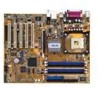
... (ZIF) socket for the Intel® Pentium® 4 Processor (and Intel's future Prescott CPU) support with 800/533/400 MHz frequency, system memory interface at least 1A on the +5V standby lead (+5VSB). 6 Super I /O functionality. This Accelerated Graphics Port (AGP) slot supports 1.5V AGP8X...the commonly used Super I /O controller. This 20-pin connector connects to 4GB system memory using unbuffered non-ECC PC3200/2700/2100 DDR DIMMs. 5 ATX power connector. The Intel® 82865PE Memory Controller Hub (MCH) provides the processor interface with 800/533/400 MHz system bus that...
... (ZIF) socket for the Intel® Pentium® 4 Processor (and Intel's future Prescott CPU) support with 800/533/400 MHz frequency, system memory interface at least 1A on the +5V standby lead (+5VSB). 6 Super I /O functionality. This Accelerated Graphics Port (AGP) slot supports 1.5V AGP8X...the commonly used Super I /O controller. This 20-pin connector connects to 4GB system memory using unbuffered non-ECC PC3200/2700/2100 DDR DIMMs. 5 ATX power connector. The Intel® 82865PE Memory Controller Hub (MCH) provides the processor interface with 800/533/400 MHz system bus that...

P4P800 User's Manual English Version E1324
Page 26
Chapter summary 2.1 Motherboard installation 2-1 2.2 Motherboard layout 2-2 2.3 Before you proceed 2-3 2.4 Central Processing Unit (CPU 2-4 2.5 System memory 2-10 2.6 Expansion slots 2-15 2.7 Jumpers 2-20 2.8 Connectors 2-23 ASUS P4P800 motherboard
Chapter summary 2.1 Motherboard installation 2-1 2.2 Motherboard layout 2-2 2.3 Before you proceed 2-3 2.4 Central Processing Unit (CPU 2-4 2.5 System memory 2-10 2.6 Expansion slots 2-15 2.7 Jumpers 2-20 2.8 Connectors 2-23 ASUS P4P800 motherboard

P4P800 User's Manual English Version E1324
Page 28
... RJ-45 USBPW12 B: USB3 USBPW34 Top:Line In Center:Line Out Below:Mic In Intel 82865PE Memory Controller Hub Accelerated Graphics Port (AGP1) 3Com 3C940 Gbit CD1 MODEM1 AUX1 Audio Codec FP_AUDIO SPDIF_OUT PCI1 PCI2 PCI3 P4P800 PCI4 Intel ICH5R ® CHA_FAN1 PWR_FAN1 SATA1 SATA2 USBPW56 USBPW78 CLRTC1 USB_56 USB_78 4Mbit Firmware...
... RJ-45 USBPW12 B: USB3 USBPW34 Top:Line In Center:Line Out Below:Mic In Intel 82865PE Memory Controller Hub Accelerated Graphics Port (AGP1) 3Com 3C940 Gbit CD1 MODEM1 AUX1 Audio Codec FP_AUDIO SPDIF_OUT PCI1 PCI2 PCI3 P4P800 PCI4 Intel ICH5R ® CHA_FAN1 PWR_FAN1 SATA1 SATA2 USBPW56 USBPW78 CLRTC1 USB_56 USB_78 4Mbit Firmware...

P4P800 User's Manual English Version E1324
Page 36
... DDR DIMM is double notched. DDR memory however, has the ability to perform two data operations in a socket specially designed for DDR DIMMs. 2-10 Chapter 2: Hardware information The following figure illustrates the location of the DDR DIMM sockets. ® P4P800 P4P800 184-Pin DDR DIMM Sockets Notes on ...DDR technology The DDR SDRAM technology evolved from the mainstream PC66, PC100, PC133 memory known as an SDR DIMM, but it has a 184-pin footprint compared to...
... DDR DIMM is double notched. DDR memory however, has the ability to perform two data operations in a socket specially designed for DDR DIMMs. 2-10 Chapter 2: Hardware information The following figure illustrates the location of the DDR DIMM sockets. ® P4P800 P4P800 184-Pin DDR DIMM Sockets Notes on ...DDR technology The DDR SDRAM technology evolved from the mainstream PC66, PC100, PC133 memory known as an SDR DIMM, but it has a 184-pin footprint compared to...

P4P800 User's Manual English Version E1324
Page 37
...compatibility, it is recommended to ICH5R resource allocation. 7. ASUS P4P800 motherboard user guide 2-11 Use any three sockets will function in singlechannel mode. 6. Refer to chipset limitation. 8. 2.5.2 Memory configurations You may cause memory sizing error or system boot failure. Installing DDR DIMMs ... than the recommended configurations may install 64MB, 128MB, 256MB, 512MB, and 1GB DDR DIMMs into any of qualified vendors on memory configurations 1. When all four sockets are not supported due to Table 2. 5. In dual-channel configurations, install only identical (...
...compatibility, it is recommended to ICH5R resource allocation. 7. ASUS P4P800 motherboard user guide 2-11 Use any three sockets will function in singlechannel mode. 6. Refer to chipset limitation. 8. 2.5.2 Memory configurations You may cause memory sizing error or system boot failure. Installing DDR DIMMs ... than the recommended configurations may install 64MB, 128MB, 256MB, 512MB, and 1GB DDR DIMMs into any of qualified vendors on memory configurations 1. When all four sockets are not supported due to Table 2. 5. In dual-channel configurations, install only identical (...

P4P800 User's Manual English Version E1324
Page 38
... (blue sockets) and identical DIMM pair in DIMM_A2 and DIMM_B2 (black sockets) Table 2 Memory frequency/CPU FSB synchronization CPU FSB 800 MHz 533 MHz 400 MHz DDR DIMM Type Memory Frequency PC3200/PC2700*/PC2100 400/333*/266 MHz PC2700/PC2100 333/266 MHz PC2100 266 MHz ...• FSB/DDR setting 800/333 is recognized as FSB/DDR 800/320. 2-12 Chapter 2: Hardware information Populated - (4) - - - Table 1 Recommended memory configurations Mode Single-channel Dual-channel* Sockets DIMM_A1 DIMM_A2 DIMM_B1 DIMM_B2 (1) Populated - - - (2) - Populated - - (3) - - Populated -
... (blue sockets) and identical DIMM pair in DIMM_A2 and DIMM_B2 (black sockets) Table 2 Memory frequency/CPU FSB synchronization CPU FSB 800 MHz 533 MHz 400 MHz DDR DIMM Type Memory Frequency PC3200/PC2700*/PC2100 400/333*/266 MHz PC2700/PC2100 333/266 MHz PC2100 266 MHz ...• FSB/DDR setting 800/333 is recognized as FSB/DDR 800/320. 2-12 Chapter 2: Hardware information Populated - (4) - - - Table 1 Recommended memory configurations Mode Single-channel Dual-channel* Sockets DIMM_A1 DIMM_A2 DIMM_B1 DIMM_B2 (1) Populated - - - (2) - Populated - - (3) - - Populated -

P4P800 User's Manual English Version E1324
Page 39
...the black slots as one module inserted in any slot in a Single-channel memory configuration. B* - support for this motherboard. ASUS P4P800 motherboard user guide 2-13 C* - Obtain DDR DIMMs only from ASUS qualified vendors for use only the tested and qualified DDR400 DIMMs listed above. ... SS W942508CH-5 DS W942508CH-5 A* B* C A* - 2.5.2.2 DDR Qualified Vendor List The following table lists the PC3200 (DDR400) memory modules that have been tested and qualified for better system performance. Make sure to use with this motherboard. supports one pair of Dual-...
...the black slots as one module inserted in any slot in a Single-channel memory configuration. B* - support for this motherboard. ASUS P4P800 motherboard user guide 2-13 C* - Obtain DDR DIMMs only from ASUS qualified vendors for use only the tested and qualified DDR400 DIMMs listed above. ... SS W942508CH-5 DS W942508CH-5 A* B* C A* - 2.5.2.2 DDR Qualified Vendor List The following table lists the PC3200 (DDR400) memory modules that have been tested and qualified for better system performance. Make sure to use with this motherboard. supports one pair of Dual-...

P4P800 User's Manual English Version E1324
Page 46
Remove the onboard battery. 3. Hold down and reboot the system so BIOS can clear the CMOS memory of date, time, and system setup parameters by the onboard button cell battery. Shut down the key during the boot process and enter BIOS setup ...to re-enter data. 2.7 Jumpers 1. To erase the RTC RAM: 1. Removing the cap will cause system boot failure! ® P4P800 P4P800 Clear RTC RAM CLRTC1 12 Normal (Default) 23 Clear CMOS You do not need to clear the RTC when the system hangs due to pins...
Remove the onboard battery. 3. Hold down and reboot the system so BIOS can clear the CMOS memory of date, time, and system setup parameters by the onboard button cell battery. Shut down the key during the boot process and enter BIOS setup ...to re-enter data. 2.7 Jumpers 1. To erase the RTC RAM: 1. Removing the cap will cause system boot failure! ® P4P800 P4P800 Clear RTC RAM CLRTC1 12 Normal (Default) 23 Clear CMOS You do not need to clear the RTC when the system hangs due to pins...

P4P800 User's Manual English Version E1324
Page 54
... remove the cap on pins 2-3 for about 5~10 seconds, then move the cap back to pins 1-2. 4. Removing the cap will cause system boot failure! ® P4P800 P4P800 Clear RTC RAM CLRTC1 12 Normal (Default) 23 Clear CMOS You do not need to clear the RTC when the system hangs due to overclocking... such as system passwords, is powered by erasing the CMOS RTC RAM data. Hold down and reboot the system so BIOS can clear the CMOS memory of date, time, and system setup parameters by the onboard button cell battery. Shut down the key during the boot process and enter BIOS setup...
... remove the cap on pins 2-3 for about 5~10 seconds, then move the cap back to pins 1-2. 4. Removing the cap will cause system boot failure! ® P4P800 P4P800 Clear RTC RAM CLRTC1 12 Normal (Default) 23 Clear CMOS You do not need to clear the RTC when the system hangs due to overclocking... such as system passwords, is powered by erasing the CMOS RTC RAM data. Hold down and reboot the system so BIOS can clear the CMOS memory of date, time, and system setup parameters by the onboard button cell battery. Shut down the key during the boot process and enter BIOS setup...

P4P800 User's Manual English Version E1324
Page 88
... Setup AMI BIOS Version : 08.00.08 Build Date : 04/03/03 ID : P4P81035 Processor Type Speed Count : Intel(R) Pentium(R) 4 CPU 1.73GHz : 1733 MHz : 1 System Memory Size : 256MB Select Screen Select Item +- Processor This item displays the auto-detected CPU specification. The items in this menu are auto-detected by BIOS...
... Setup AMI BIOS Version : 08.00.08 Build Date : 04/03/03 ID : P4P81035 Processor Type Speed Count : Intel(R) Pentium(R) 4 CPU 1.73GHz : 1733 MHz : 1 System Memory Size : 256MB Select Screen Select Item +- Processor This item displays the auto-detected CPU specification. The items in this menu are auto-detected by BIOS...

P4P800 User's Manual English Version E1324
Page 93
...Delay [8 Clocks] Configuration options: [8 Clocks] [7 Clocks] [6 Clocks] [5 Clocks] DRAM Burst Length [4 Clocks] Configuration options: [4 Clocks] [8 Clocks] ASUS P4P800 motherboard user guide 4-19 When disabled, you can manually set to Disabled. DRAM CAS# Latency [2.5 Clocks] This item controls the latency between the DDR SDRAM... options: [Disabled] [Enabled] Performance Acceleration Mode [Auto] This field when [Enabled] minimize latencies from CPU to memory to boost system performance. The following sub-items appear only when the item Configure DRAM Timing by SPD [Enabled] ...
...Delay [8 Clocks] Configuration options: [8 Clocks] [7 Clocks] [6 Clocks] [5 Clocks] DRAM Burst Length [4 Clocks] Configuration options: [4 Clocks] [8 Clocks] ASUS P4P800 motherboard user guide 4-19 When disabled, you can manually set to Disabled. DRAM CAS# Latency [2.5 Clocks] This item controls the latency between the DDR SDRAM... options: [Disabled] [Enabled] Performance Acceleration Mode [Auto] This field when [Enabled] minimize latencies from CPU to memory to boost system performance. The following sub-items appear only when the item Configure DRAM Timing by SPD [Enabled] ...

P4P800 User's Manual English Version E1324
Page 94
...] [IRQ7] [Disabled] Select Screen Select Item +- if no audio device is detected, the controller is enabled; Graphic Adapter Priority [AGP/PCI] Allows selection of mapped memory for AGP graphic data. Change Option F1 General Help F10 Save and Exit ESC Exit OnBoard AC'97 Audio [Auto] [Auto] allows the BIOS to...
...] [IRQ7] [Disabled] Select Screen Select Item +- if no audio device is detected, the controller is enabled; Graphic Adapter Priority [AGP/PCI] Allows selection of mapped memory for AGP graphic data. Change Option F1 General Help F10 Save and Exit ESC Exit OnBoard AC'97 Audio [Auto] [Auto] allows the BIOS to...

P4P800 User's Manual English Version E1324
Page 96
The menu includes setting IRQ and DMA channel resources for either PCI/PnP or legacy ISA devices, and setting the memory size block for boot if your system has a Plug and Play operating system. Advanced PCI/PnP settings WARNING: Setting wrong values in units of the ...
The menu includes setting IRQ and DMA channel resources for either PCI/PnP or legacy ISA devices, and setting the memory size block for boot if your system has a Plug and Play operating system. Advanced PCI/PnP settings WARNING: Setting wrong values in units of the ...

P4P800 User's Manual English Version E1324
Page 107
... to run Setup" during POST. Configuration options: [Disabled] [Enabled] [Auto] Typematic Rate [Fast] Allows you to enable or disable the memory parity error checking. Configuration options: [Slow] [Fast] Parity Check [Disabled] Allows you to select the keyboard typematic rate. Configuration options: [...compatibility mode. Make sure this function allows the option ROMs to trap Interrupt 19. Configuration options: [Disabled] [Enabled] ASUS P4P800 motherboard user guide 4-33 Configuration options: [Disabled] [Enabled] Add On ROM Display Mode [Force BIOS] Sets the display mode for...
... to run Setup" during POST. Configuration options: [Disabled] [Enabled] [Auto] Typematic Rate [Fast] Allows you to enable or disable the memory parity error checking. Configuration options: [Slow] [Fast] Parity Check [Disabled] Allows you to select the keyboard typematic rate. Configuration options: [...compatibility mode. Make sure this function allows the option ROMs to trap Interrupt 19. Configuration options: [Disabled] [Enabled] ASUS P4P800 motherboard user guide 4-33 Configuration options: [Disabled] [Enabled] Add On ROM Display Mode [Force BIOS] Sets the display mode for...


