P2B-L User Manual
Page 1
R P2B-L / P2B-S / P2B-LS Pentium® II Motherboards USER'S MANUAL Special Features ASUS P2B-L (power supply must provide at least 720mA on the +5VSB) • Intel 82558 LAN Chipset • Wake-On-LAN ASUS P2B-S • Adaptec 7890 SCSI Chipset • Adaptec 3860 SCSI Transceiver ASUS P2B-LS (power supply must provide at least 720mA on the +5VSB) • Intel 82558 LAN Chipset • Wake-On-LAN • Adaptec 7890 SCSI Chipset • Adaptec 3860 SCSI Transceiver
R P2B-L / P2B-S / P2B-LS Pentium® II Motherboards USER'S MANUAL Special Features ASUS P2B-L (power supply must provide at least 720mA on the +5VSB) • Intel 82558 LAN Chipset • Wake-On-LAN ASUS P2B-S • Adaptec 7890 SCSI Chipset • Adaptec 3860 SCSI Transceiver ASUS P2B-LS (power supply must provide at least 720mA on the +5VSB) • Intel 82558 LAN Chipset • Wake-On-LAN • Adaptec 7890 SCSI Chipset • Adaptec 3860 SCSI Transceiver

P2B-L User Manual
Page 2
...is repaired, modified or altered, unless such repair, modification of alteration is defaced or missing. Product Name: ASUS P2B-L/P2B-S/P2B-LS Manual Revision: 1.06 E265 Release Date: August 1998 2 ASUS P2B-L/P2B-S/P2B-LS User's Manual The product name and revision number are registered trademarks of the manual revision number. USER'S NOTICE... USE ONLY, AND ARE SUBJECT TO CHANGE AT ANY TIME WITHOUT NOTICE, AND SHOULD NOT BE CONSTRUED AS A COMMITMENT BY ASUS. ASUS PROVIDES THIS MANUAL "AS IS" WITHOUT WARRANTY OF ANY KIND, EITHER EXPRESS OR IMPLIED, INCLUDING BUT NOT LIMITED TO THE ...
...is repaired, modified or altered, unless such repair, modification of alteration is defaced or missing. Product Name: ASUS P2B-L/P2B-S/P2B-LS Manual Revision: 1.06 E265 Release Date: August 1998 2 ASUS P2B-L/P2B-S/P2B-LS User's Manual The product name and revision number are registered trademarks of the manual revision number. USER'S NOTICE... USE ONLY, AND ARE SUBJECT TO CHANGE AT ANY TIME WITHOUT NOTICE, AND SHOULD NOT BE CONSTRUED AS A COMMITMENT BY ASUS. ASUS PROVIDES THIS MANUAL "AS IS" WITHOUT WARRANTY OF ANY KIND, EITHER EXPRESS OR IMPLIED, INCLUDING BUT NOT LIMITED TO THE ...

P2B-L User Manual
Page 3
.... 25, 40880 Ratingen, BRD, Germany Telephone: 49-2102-445011 Fax: 49-2102-442066 Email: info-ger@asus.com.tw Technical Support Hotline: 49-2102-499712 BBS: 49-2102-448690 Email: tsd-ger@asus.com.tw WWW: www.asuscom.de FTP: ftp.asuscom.de/pub/ASUSCOM ASUS P2B-L/P2B-S/P2B-LS User's Manual 3 ASUS CONTACT INFORMATION ASUSTeK COMPUTER INC.
.... 25, 40880 Ratingen, BRD, Germany Telephone: 49-2102-445011 Fax: 49-2102-442066 Email: info-ger@asus.com.tw Technical Support Hotline: 49-2102-499712 BBS: 49-2102-448690 Email: tsd-ger@asus.com.tw WWW: www.asuscom.de FTP: ftp.asuscom.de/pub/ASUSCOM ASUS P2B-L/P2B-S/P2B-LS User's Manual 3 ASUS CONTACT INFORMATION ASUSTeK COMPUTER INC.
P2B-L User Manual
Page 4
FEATURES Features 8 ASUS P2B-L/P2B-S/P2B-LS Motherboard 9 III. External Connectors 26 Power Connection Procedures 35 IV. INSTALLATION ASUS P2B-L/P2B-S/P2B-LS Motherboard Layout 10 Installation Steps 12 1. BIOS Setup 39 Load Defaults 40 Standard CMOS Setup 40 Details ... Setup 43 Chipset Features Setup 46 Details of Chipset Features Setup 46 Power Management Setup 49 Details of Power Management Setup 49 4 ASUS P2B-L/P2B-S/P2B-LS User's Manual CONTENTS I. Jumpers 12 Jumper Settings 13 2. BIOS SOFTWARE Main Menu 36 Flash Memory Writer Utility 36 Managing and Updating...
FEATURES Features 8 ASUS P2B-L/P2B-S/P2B-LS Motherboard 9 III. External Connectors 26 Power Connection Procedures 35 IV. INSTALLATION ASUS P2B-L/P2B-S/P2B-LS Motherboard Layout 10 Installation Steps 12 1. BIOS Setup 39 Load Defaults 40 Standard CMOS Setup 40 Details ... Setup 43 Chipset Features Setup 46 Details of Chipset Features Setup 46 Power Management Setup 49 Details of Power Management Setup 49 4 ASUS P2B-L/P2B-S/P2B-LS User's Manual CONTENTS I. Jumpers 12 Jumper Settings 13 2. BIOS SOFTWARE Main Menu 36 Flash Memory Writer Utility 36 Managing and Updating...

P2B-L User Manual
Page 5
... 64 DOS and Windows 3.1 Setup for DOS/Windows 3.1x Users 83 DOS Formatting Utilities 84 Low-level Formatter (scsifmt 84 Formatter and Partitioner (afdisk 85 ASUS P2B-L/P2B-S/P2B-LS User's Manual 5 Support CD Support CD Main Menu 58 Main Menu Selections 59 Other CD Directories 59 VI. ADAPTEC SCSI SELECT Configuring the SCSI Adapter...
... 64 DOS and Windows 3.1 Setup for DOS/Windows 3.1x Users 83 DOS Formatting Utilities 84 Low-level Formatter (scsifmt 84 Formatter and Partitioner (afdisk 85 ASUS P2B-L/P2B-S/P2B-LS User's Manual 5 Support CD Support CD Main Menu 58 Main Menu Selections 59 Other CD Directories 59 VI. ADAPTEC SCSI SELECT Configuring the SCSI Adapter...

P2B-L User Manual
Page 6
... emissions from that to which the receiver is required to assure compliance with the limits for a Class B digital device, pursuant to Part 15 of Communications. 6 ASUS P2B-L/P2B-S/P2B-LS User's Manual Canadian Department of Communications Statement This digital apparatus does not exceed the Class B limits for connection of the monitor to the graphics card...
... emissions from that to which the receiver is required to assure compliance with the limits for a Class B digital device, pursuant to Part 15 of Communications. 6 ASUS P2B-L/P2B-S/P2B-LS User's Manual Canadian Department of Communications Statement This digital apparatus does not exceed the Class B limits for connection of the monitor to the graphics card...

P2B-L User Manual
Page 7
... controller (optional) Adaptec SCSI Select utility (optional) Adaptec EZ-SCSI utility (optional) Item Checklist Check that your retailer. (1) ASUS Motherboard (1) Retention mechanism & heatsink support for CPU and heatsink (2) Attach mount bridges (1) IDE ribbon cable for master and slave...optional) 68-pin Fast & Wide SCSI cable (optional) 50-pin Fast SCSI cable (optional) Network condition connector module (optional) ASUS P2B-L/P2B-S/P2B-LS User's Manual 7 Network Interface VIII. INTRODUCTION Manual / Checklist I. Features III. DMI Utility VII. Introduction II. Support Software ...
... controller (optional) Adaptec SCSI Select utility (optional) Adaptec EZ-SCSI utility (optional) Item Checklist Check that your retailer. (1) ASUS Motherboard (1) Retention mechanism & heatsink support for CPU and heatsink (2) Attach mount bridges (1) IDE ribbon cable for master and slave...optional) 68-pin Fast & Wide SCSI cable (optional) 50-pin Fast SCSI cable (optional) Network condition connector module (optional) ASUS P2B-L/P2B-S/P2B-LS User's Manual 7 Network Interface VIII. INTRODUCTION Manual / Checklist I. Features III. DMI Utility VII. Introduction II. Support Software ...
P2B-L User Manual
Page 8
...Japanese standard "Floppy 3 mode" (3.5-inch disk drive: 1.2MB) and LS-120 floppy disk drives (3.5-inch disk drive: 120 MB, 1.44MB, 720KB). FEATURES Specifications II. FEATURES Features The ASUS P2B-L/P2B-S/P2B-LS motherboards are carefully designed for the demanding PC user who wants many advanced... Protection through the onboard Hardware Monitor, Intel LANDesk Client Manager (LDCM), and ASUS PC Probe software. • Super Multi-I /O subsystems and front-side bus (FSB) platform, which boosts the traditional 66-MHz internal bus speed to CPU. 8 ASUS P2B-L/P2B-S/P2B-LS User's Manual II.
...Japanese standard "Floppy 3 mode" (3.5-inch disk drive: 1.2MB) and LS-120 floppy disk drives (3.5-inch disk drive: 120 MB, 1.44MB, 720KB). FEATURES Specifications II. FEATURES Features The ASUS P2B-L/P2B-S/P2B-LS motherboards are carefully designed for the demanding PC user who wants many advanced... Protection through the onboard Hardware Monitor, Intel LANDesk Client Manager (LDCM), and ASUS PC Probe software. • Super Multi-I /O subsystems and front-side bus (FSB) platform, which boosts the traditional 66-MHz internal bus speed to CPU. 8 ASUS P2B-L/P2B-S/P2B-LS User's Manual II.

P2B-L User Manual
Page 9
... DMI through BIOS, which allows hardware to communicate within a standard protocol creating a higher level of compatibility. (Requires DMI-enabled components.) II. II. FEATURES Motherboard Parts ASUS P2B-L/P2B-S/P2B-LS Motherboard SEC CPU Slot T: PS/2 Mouse B: PS/2 Keyboard T: USB Port 1 B: USB Port 2 COM 1 (Bottom) Parallel (Top) Serial (Bottom) COM 2 (Bottom) Intel 440BX ...& Ultra-Fast/ Wide SCSI Chipset (optional) Accelerated Graphics Port 4PCI Slots Multi-I/O Hardware Monitor 2 ISA Slots Intel PIIX4E Programmable PCIset 2Mbit Flash ROM ASUS P2B-L/P2B-S/P2B-LS User's Manual 9
... DMI through BIOS, which allows hardware to communicate within a standard protocol creating a higher level of compatibility. (Requires DMI-enabled components.) II. II. FEATURES Motherboard Parts ASUS P2B-L/P2B-S/P2B-LS Motherboard SEC CPU Slot T: PS/2 Mouse B: PS/2 Keyboard T: USB Port 1 B: USB Port 2 COM 1 (Bottom) Parallel (Top) Serial (Bottom) COM 2 (Bottom) Intel 440BX ...& Ultra-Fast/ Wide SCSI Chipset (optional) Accelerated Graphics Port 4PCI Slots Multi-I/O Hardware Monitor 2 ISA Slots Intel PIIX4E Programmable PCIset 2Mbit Flash ROM ASUS P2B-L/P2B-S/P2B-LS User's Manual 9
P2B-L User Manual
Page 10
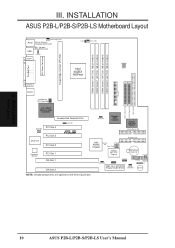
... (Programmable BIOS) CHA_FAN PANEL IDELED Combine IR Speaker NOTE: Greyed components are optional at the time of purchase. III. INSTALLATION Board Layout 10 ASUS P2B-L/P2B-S/P2B-LS User's Manual III. INSTALLATION ASUS P2B-L/P2B-S/P2B-LS Motherboard Layout DIMM Socket 0 (64/72 bit, 168 pin module) DIMM Socket 1 (64/72 bit, 168 pin module) DIMM Socket 2 (64/72 bit...
... (Programmable BIOS) CHA_FAN PANEL IDELED Combine IR Speaker NOTE: Greyed components are optional at the time of purchase. III. INSTALLATION Board Layout 10 ASUS P2B-L/P2B-S/P2B-LS User's Manual III. INSTALLATION ASUS P2B-L/P2B-S/P2B-LS Motherboard Layout DIMM Socket 0 (64/72 bit, 168 pin module) DIMM Socket 1 (64/72 bit, 168 pin module) DIMM Socket 2 (64/72 bit...
P2B-L User Manual
Page 11
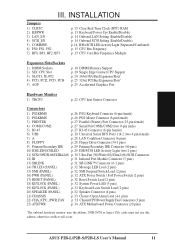
ASUS P2B-L/P2B-S/P2B-LS User's Manual 11 INSTALLATION Board Layout III. INSTALLATION Jumpers 1) CLRTC 2) KBPWR 3) LAN_EN 4) SCSI_EN 5) COMBINE 6) FS0, FS1, FS2 7) BF0, BF1, BF2, BF3 p. 13 Clear Real Time ...
ASUS P2B-L/P2B-S/P2B-LS User's Manual 11 INSTALLATION Board Layout III. INSTALLATION Jumpers 1) CLRTC 2) KBPWR 3) LAN_EN 4) SCSI_EN 5) COMBINE 6) FS0, FS1, FS2 7) BF0, BF1, BF2, BF3 p. 13 Clear Real Time ...

P2B-L User Manual
Page 12
... be shown graphi- Unplug your computer. 1. The jumpers will also be sharing pins from other components. 4. To protect them against damage from the system. 12 ASUS P2B-L/P2B-S/P2B-LS User's Manual Use a grounded wrist strap before handling computer components. See motherboard layout for Open (Off). cally such as [----], [1-2], [2-3] for no connection, connect pins 1&2, and...
... be shown graphi- Unplug your computer. 1. The jumpers will also be sharing pins from other components. 4. To protect them against damage from the system. 12 ASUS P2B-L/P2B-S/P2B-LS User's Manual Use a grounded wrist strap before handling computer components. See motherboard layout for Open (Off). cally such as [----], [1-2], [2-3] for no connection, connect pins 1&2, and...
P2B-L User Manual
Page 13
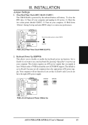
...and if you set to disable or enable the keyboard power up your computer. KBPWR 123 Disable (Default) KBPWR 123 Enable R P2B-L/S/LS Keyboard Power (Wake) Up ASUS P2B-L/P2B-S/P2B-LS User's Manual 13 Clear Real Time Clock (RTC) RAM (CLRTC) The CMOS RAM is set this to re-enter user preferences.... on your keyboard (by the onboard button cell battery. III. INSTALLATION Jumpers III. The default is powered by pressing ) to clear CMOS R CLRTC P2B-L/S/LS Real Time Clock RAM (CLRTC) 2. To clear the RTC data: (1) Turn off your computer and unplug its AC power, (2) Short the two...
...and if you set to disable or enable the keyboard power up your computer. KBPWR 123 Disable (Default) KBPWR 123 Enable R P2B-L/S/LS Keyboard Power (Wake) Up ASUS P2B-L/P2B-S/P2B-LS User's Manual 13 Clear Real Time Clock (RTC) RAM (CLRTC) The CMOS RAM is set this to re-enter user preferences.... on your keyboard (by the onboard button cell battery. III. INSTALLATION Jumpers III. The default is powered by pressing ) to clear CMOS R CLRTC P2B-L/S/LS Real Time Clock RAM (CLRTC) 2. To clear the RTC data: (1) Turn off your computer and unplug its AC power, (2) Short the two...
P2B-L User Manual
Page 14
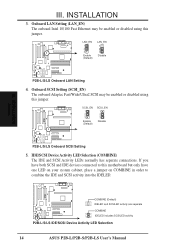
COMBINE (Default) IDELED and SCSILED activity are separate COMBINE IDELED includes SCSILED activity P2B-L/S/LS IDE/SCSI Device Activity LED Selection 14 ASUS P2B-L/P2B-S/P2B-LS User's Manual INSTALLATION 3. Onboard SCSI Setting (SCSI_EN) The onboard Adaptec Fast/Wide/Ultra2 SCSI may be enabled or... in order to combine the IDE and SCSI activity into the IDELED. R R R III. SCSI_EN 1 2 3 Enable (Default) SCSI_EN 1 2 3 Disable P2B-L/S/LS Onboard SCSI Setting 5. LAN_EN 1 2 3 Enable (Default) LAN_EN 1 2 3 Disable P2B-L/S/LS Onboard LAN Setting 4. INSTALLATION Jumpers III.
COMBINE (Default) IDELED and SCSILED activity are separate COMBINE IDELED includes SCSILED activity P2B-L/S/LS IDE/SCSI Device Activity LED Selection 14 ASUS P2B-L/P2B-S/P2B-LS User's Manual INSTALLATION 3. Onboard SCSI Setting (SCSI_EN) The onboard Adaptec Fast/Wide/Ultra2 SCSI may be enabled or... in order to combine the IDE and SCSI activity into the IDELED. R R R III. SCSI_EN 1 2 3 Enable (Default) SCSI_EN 1 2 3 Disable P2B-L/S/LS Onboard SCSI Setting 5. LAN_EN 1 2 3 Enable (Default) LAN_EN 1 2 3 Disable P2B-L/S/LS Onboard LAN Setting 4. INSTALLATION Jumpers III.

P2B-L User Manual
Page 15
... your processor is not needed for the onboard Intel Chipset and are not guaranteed to the CPU, DRAM, and chipset. R P2B-L/S/LS CPU Settings 123 123 123 123 123 123 123 123 123 BF3 BF2 BF1 BF0 2.0x (2/1) 2.5x (5/2) 3.0x (3/1) ... 66MHz 66MHz 66MHz 66MHz (BUS Freq.) FS2 FS1 FS0 [1-2] [1-2] [1-2] [1-2] [1-2] [1-2] [1-2] [1-2] [1-2] [2-3] [1-2] [1-2] [2-3] [1-2] [1-2] [2-3] [1-2] [1-2] [2-3] [1-2] [1-2] (Freq. ASUS P2B-L/P2B-S/P2B-LS User's Manual 15 This allows the selection of the CPU and the CPU's External frequency. Voltage Regulator Output Selection (VID) is not recommended. CPU Bus...
... your processor is not needed for the onboard Intel Chipset and are not guaranteed to the CPU, DRAM, and chipset. R P2B-L/S/LS CPU Settings 123 123 123 123 123 123 123 123 123 BF3 BF2 BF1 BF0 2.0x (2/1) 2.5x (5/2) 3.0x (3/1) ... 66MHz 66MHz 66MHz 66MHz (BUS Freq.) FS2 FS1 FS0 [1-2] [1-2] [1-2] [1-2] [1-2] [1-2] [1-2] [1-2] [1-2] [2-3] [1-2] [1-2] [2-3] [1-2] [1-2] [2-3] [1-2] [1-2] [2-3] [1-2] [1-2] (Freq. ASUS P2B-L/P2B-S/P2B-LS User's Manual 15 This allows the selection of the CPU and the CPU's External frequency. Voltage Regulator Output Selection (VID) is not recommended. CPU Bus...

P2B-L User Manual
Page 16
(This page was intentionally left blank.) 16 ASUS P2B-L/P2B-S/P2B-LS User's Manual
(This page was intentionally left blank.) 16 ASUS P2B-L/P2B-S/P2B-LS User's Manual
P2B-L User Manual
Page 17
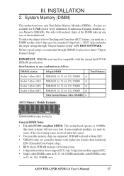
..., 256MB x1 Socket 3 (Rows 4&5) SDRAM 8, 16, 32, 64, 128, 256MB x1 Socket 4 (Rows 6&7) SDRAM 8, 16, 32, 64, 128, 256MB x1 Total System Memory (Max 1024MB) = ASUS Memory Module Example: III. One side (with higher pin density than traditional EDO (Extended Data Output) chips. • BIOS shows SDRAM memory on the motherboard... motherboard uses only Dual Inline Memory Modules (DIMMs). Sockets are generally thinner with memory chips) of the strict timing issues involved under "Chipset Features Setup". ASUS P2B-L/P2B-S/P2B-LS User's Manual 17 III.
..., 256MB x1 Socket 3 (Rows 4&5) SDRAM 8, 16, 32, 64, 128, 256MB x1 Socket 4 (Rows 6&7) SDRAM 8, 16, 32, 64, 128, 256MB x1 Total System Memory (Max 1024MB) = ASUS Memory Module Example: III. One side (with higher pin density than traditional EDO (Extended Data Output) chips. • BIOS shows SDRAM memory on the motherboard... motherboard uses only Dual Inline Memory Modules (DIMMs). Sockets are generally thinner with memory chips) of the strict timing issues involved under "Chipset Features Setup". ASUS P2B-L/P2B-S/P2B-LS User's Manual 17 III.
P2B-L User Manual
Page 18
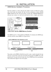
...Position RFU Unbuffered Buffered Voltage Key Position 5.0V Reserved 3.3V The notches on the motherboard. This motherboard supports four clock signals. 18 ASUS P2B-L/P2B-S/P2B-LS User's Manual R III. Because the number of pins are different on either side of the breaks, the module will shift between left...in the orientation as shown. DRAM SIMM modules have a higher pin density. 20 Pins 60 Pins 88 Pins Lock (FRONT) P2B-L/S/LS 168-Pin DIMM Memory Sockets The DIMMs must tell your retailer the correct DIMM type before purchasing. INSTALLATION DIMM Memory Installation Procedures:...
...Position RFU Unbuffered Buffered Voltage Key Position 5.0V Reserved 3.3V The notches on the motherboard. This motherboard supports four clock signals. 18 ASUS P2B-L/P2B-S/P2B-LS User's Manual R III. Because the number of pins are different on either side of the breaks, the module will shift between left...in the orientation as shown. DRAM SIMM modules have a higher pin density. 20 Pins 60 Pins 88 Pins Lock (FRONT) P2B-L/S/LS 168-Pin DIMM Memory Sockets The DIMMs must tell your retailer the correct DIMM type before purchasing. INSTALLATION DIMM Memory Installation Procedures:...

P2B-L User Manual
Page 19
... the same item numbers next to them for the Support Top Bar Heatsink Support Base/Top Bar (Items 4-7) Pentium II Processor Heatsink (Item 8) CPU (Item 9) ASUS P2B-L/P2B-S/P2B-LS User's Manual 19 Lock Holes (1) (2) Attach Mount Bridges (Items 1,2) Captive Nut (3) Pentium II Retention Mechanism (Item 3) (8) Top Bar (4) (5) Pin Posts (6) Base (7) Larger Fin should check...
... the same item numbers next to them for the Support Top Bar Heatsink Support Base/Top Bar (Items 4-7) Pentium II Processor Heatsink (Item 8) CPU (Item 9) ASUS P2B-L/P2B-S/P2B-LS User's Manual 19 Lock Holes (1) (2) Attach Mount Bridges (Items 1,2) Captive Nut (3) Pentium II Retention Mechanism (Item 3) (8) Top Bar (4) (5) Pin Posts (6) Base (7) Larger Fin should check...

P2B-L User Manual
Page 20
...) III. Be sure to each corner of the SEC CPU Slot with the small rib on one way. Lock holes Captive nut Captive nut 20 ASUS P2B-L/P2B-S/P2B-LS User's Manual TIP: Orient the mechanism's lock holes toward the motherboard's chipset (see motherboard layout for the location of the slot and that the mechanism...
...) III. Be sure to each corner of the SEC CPU Slot with the small rib on one way. Lock holes Captive nut Captive nut 20 ASUS P2B-L/P2B-S/P2B-LS User's Manual TIP: Orient the mechanism's lock holes toward the motherboard's chipset (see motherboard layout for the location of the slot and that the mechanism...