User Manual
Page 11
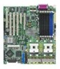
... socket for ASUS® Server Management Board Intel® ICH5R Southbridge supports: - 4 x Ultra DMA 100/66/33 hard disk drives - 2 x SATA-150 with RAID 0, RAID 1 configuration (NCL-DE/SCSI model only) Adaptec® AIC-7902W PCI-X Dual U320 SCSI controller supports: - 2 x SCSI channels with PCI Express 1.0a specifications Intel® ICH5R Southbridge supports: - 4 USB 2.0/1.1 ports (2 on the...
... socket for ASUS® Server Management Board Intel® ICH5R Southbridge supports: - 4 x Ultra DMA 100/66/33 hard disk drives - 2 x SATA-150 with RAID 0, RAID 1 configuration (NCL-DE/SCSI model only) Adaptec® AIC-7902W PCI-X Dual U320 SCSI controller supports: - 2 x SCSI channels with PCI Express 1.0a specifications Intel® ICH5R Southbridge supports: - 4 USB 2.0/1.1 ports (2 on the...
User Manual
Page 12
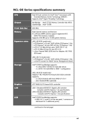
... panel Internal connectors Power Requirement Form Factor Support CD contents ASUS Smart Fan Control ASUS CrashFree BIOS 2 ASUS MyLogo2 AMI BIOS, 8 Mb FWH, Green, PnP, DMI2.0a, ACPI 2.0a SMBIOS 2.3, WfM2.0 1 x PS/2 keyboard port (purple) 1 x PS/2 mouse port (green) 2 x USB 2.0 ports 1 x Serial port 1 x VGA port 2 x LAN (RJ-45) ports 1 x Parallel port (NCL-DE/SCSI model only) 1 x Floppy disk drive connector 2 x IDE connectors 2 x Serial...
... panel Internal connectors Power Requirement Form Factor Support CD contents ASUS Smart Fan Control ASUS CrashFree BIOS 2 ASUS MyLogo2 AMI BIOS, 8 Mb FWH, Green, PnP, DMI2.0a, ACPI 2.0a SMBIOS 2.3, WfM2.0 1 x PS/2 keyboard port (purple) 1 x PS/2 mouse port (green) 2 x USB 2.0 ports 1 x Serial port 1 x VGA port 2 x LAN (RJ-45) ports 1 x Parallel port (NCL-DE/SCSI model only) 1 x Floppy disk drive connector 2 x IDE connectors 2 x Serial...
User Manual
Page 17
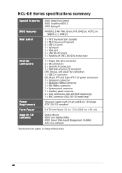
...) to provide a total solution for thinner, more flexible cables with USB 1.1. The SATA specification allows for your networking needs. ASUS NCL-DE Series 1-3 The system fan rotations per minute (RPM) is backward compatible with lower pin count, reduced voltage requirement, and up... 0 (striping), RAID 1 (mirroring), and RAID 0+1 configurations. Zero-Channel RAID (ZCR) solution (NCL-DE/SCSI model only) The motherboard comes with dual Gigabit LAN controllers and ports to prevent overheating and damage. Temperature, fan, and voltage monitoring The CPU temperature is monitored by the...
...) to provide a total solution for thinner, more flexible cables with USB 1.1. The SATA specification allows for your networking needs. ASUS NCL-DE Series 1-3 The system fan rotations per minute (RPM) is backward compatible with lower pin count, reduced voltage requirement, and up... 0 (striping), RAID 1 (mirroring), and RAID 0+1 configurations. Zero-Channel RAID (ZCR) solution (NCL-DE/SCSI model only) The motherboard comes with dual Gigabit LAN controllers and ports to prevent overheating and damage. Temperature, fan, and voltage monitoring The CPU temperature is monitored by the...
User Manual
Page 22
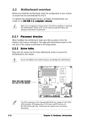
...ports goes to the rear part of the chassis as indicated in the image below. 2.2.2 Screw holes Place nine (9) screws into the chassis in the correct orientation. To optimize the motherboard features, we highly recommend that you install it . NCL-DE Series ® Place this side towards the rear of the chassis The SCSI... above illustration. 2-2 Chapter 2: Hardware information Failure to do so can damage the motherboard. These items are for NCL-DE/SCSI model only. 2.2 Motherboard overview Before you install the motherboard, study the configuration of your chassis to ensure that ...
...ports goes to the rear part of the chassis as indicated in the image below. 2.2.2 Screw holes Place nine (9) screws into the chassis in the correct orientation. To optimize the motherboard features, we highly recommend that you install it . NCL-DE Series ® Place this side towards the rear of the chassis The SCSI... above illustration. 2-2 Chapter 2: Hardware information Failure to do so can damage the motherboard. These items are for NCL-DE/SCSI model only. 2.2 Motherboard overview Before you install the motherboard, study the configuration of your chassis to ensure that ...
User Manual
Page 25
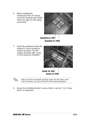
... can not install the CPU heatsinks properly. 8. Secure the motherboard with the external I/O ports toward the chassis rear panel. Before installing the motherboard into the chassis, locate the standoffs that the standoffs perfectly match the CEK spring screw holes; ASUS NCL-DE Series 2-5 Refer to section "2.2.2 Screw holes" for CPU2 7. 6. Standoffs for CPU1 Standoffs...
... can not install the CPU heatsinks properly. 8. Secure the motherboard with the external I/O ports toward the chassis rear panel. Before installing the motherboard into the chassis, locate the standoffs that the standoffs perfectly match the CEK spring screw holes; ASUS NCL-DE Series 2-5 Refer to section "2.2.2 Screw holes" for CPU2 7. 6. Standoffs for CPU1 Standoffs...
User Manual
Page 28
Keyboard power (3-pin KBPWR1) 5. Gigabit LAN controller setting (3-pin LAN1_EN1) 7. Parallel port (for NCL-DE model only) 3. VGA port 6. PCI/PCI-X slots 4. VGA controller setting (3-pin VGA_EN1) 6. SCSI controller setting (3-pin SCSI_EN1) 9. PS/2 mouse port (green) 2. CPU fan pin selection (3-pin FM_CPU1, FM_CPU2) 3. Zero-Channel RAID socket 5. Force BIOS recovery setting (3-pin RECOVERY1) Rear panel connectors 1. Serial...
Keyboard power (3-pin KBPWR1) 5. Gigabit LAN controller setting (3-pin LAN1_EN1) 7. Parallel port (for NCL-DE model only) 3. VGA port 6. PCI/PCI-X slots 4. VGA controller setting (3-pin VGA_EN1) 6. SCSI controller setting (3-pin SCSI_EN1) 9. PS/2 mouse port (green) 2. CPU fan pin selection (3-pin FM_CPU1, FM_CPU2) 3. Zero-Channel RAID socket 5. Force BIOS recovery setting (3-pin RECOVERY1) Rear panel connectors 1. Serial...
User Manual
Page 38
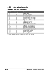
... 12 7 13 8 14 9 15 10 Standard Function System Timer Keyboard Controller Re-direct to IRQ#9 Communications Port (COM2)* Communications Port (COM1)* IRQ holder for PCI steering* Floppy Disk Controller Printer Port (LPT1)* System CMOS/Real Time Clock IRQ holder for PCI steering* IRQ holder for PCI steering* IRQ holder ...for PCI steering* PS/2 Compatible Mouse Port* Numeric Data Processor Primary IDE Channel Secondary IDE ...
... 12 7 13 8 14 9 15 10 Standard Function System Timer Keyboard Controller Re-direct to IRQ#9 Communications Port (COM2)* Communications Port (COM1)* IRQ holder for PCI steering* Floppy Disk Controller Printer Port (LPT1)* System CMOS/Real Time Clock IRQ holder for PCI steering* IRQ holder for PCI steering* IRQ holder ...for PCI steering* PS/2 Compatible Mouse Port* Numeric Data Processor Primary IDE Channel Secondary IDE ...
User Manual
Page 42
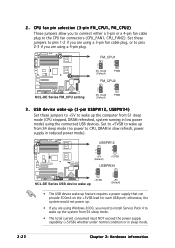
... a 4-pin fan cable plug to wake up feature requires a power supply that can provide 500mA on the +5VSB lead for each USB port; USBPW12 2 1 +5V (Default) 3 2 +5VSB NCL-DE Series ® NCL-DE Series USB device wake up USBPW34 1 2 +5VSB 2 3 +5V (Default) • The USB device wake-up the system from S4... pin selection (3-pin FM_CPU1, FM_CPU2) These jumpers allow you need to install Service Pack 4 to the CPU fan connectors (CPU_FAN1, CPU_FAN2). 2 . NCL-DE Series ® NCL-DE Series FM_CPU setting FM_CPU1 2 1 DC mode (Default) 3 2 PWM FM_CPU2 2 1 DC mode (Default) 3 2 PWM 3 .
... a 4-pin fan cable plug to wake up feature requires a power supply that can provide 500mA on the +5VSB lead for each USB port; USBPW12 2 1 +5V (Default) 3 2 +5VSB NCL-DE Series ® NCL-DE Series USB device wake up USBPW34 1 2 +5VSB 2 3 +5V (Default) • The USB device wake-up the system from S4... pin selection (3-pin FM_CPU1, FM_CPU2) These jumpers allow you need to install Service Pack 4 to the CPU fan connectors (CPU_FAN1, CPU_FAN2). 2 . NCL-DE Series ® NCL-DE Series FM_CPU setting FM_CPU1 2 1 DC mode (Default) 3 2 PWM FM_CPU2 2 1 DC mode (Default) 3 2 PWM 3 .
User Manual
Page 46
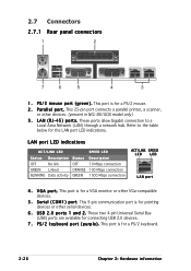
... for a PS/2 keyboard. 2-26 Chapter 2: Hardware information V G A p o r t . S e r i a l ( C O M 1 ) p o r t. These two 4-pin Universal Serial Bus (USB) ports are available for pointing devices or other devices. (present in NCL-DE/SCSI model only) 3 . This 9-pin communication port is for a PS/2 mouse. 2 . P a r a l l e l p o r t . L A N ( R J - 4 5 ) p o r t s . This 25-pin port connects a parallel printer, a scanner, or other serial devices. 6 . U S B 2 . 0 p o r t s 1 a n d 2 . Refer to a Local Area Network (LAN...
... for a PS/2 keyboard. 2-26 Chapter 2: Hardware information V G A p o r t . S e r i a l ( C O M 1 ) p o r t. These two 4-pin Universal Serial Bus (USB) ports are available for pointing devices or other devices. (present in NCL-DE/SCSI model only) 3 . This 9-pin communication port is for a PS/2 mouse. 2 . P a r a l l e l p o r t . L A N ( R J - 4 5 ) p o r t s . This 25-pin port connects a parallel printer, a scanner, or other serial devices. 6 . U S B 2 . 0 p o r t s 1 a n d 2 . Refer to a Local Area Network (LAN...
User Manual
Page 50
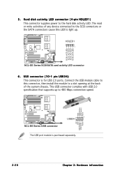
GND USB PortA(+) USB PortA(-) Power NCL-DE Series ® NC GND USB PortB(+) USB PortB(-) Power NCL-DE Series USB connector 1 USB34 The USB port module is for USB 2.0 ports. HDLED1 1 NCL-DE Series SCSI/SATA card activity LED connector 6. NCL-DE Series ® SCSI_ACTLED+ SCSI_ACTLEDSCSI_ACTLEDSCSI_ACTLED+ 5 . Connect the USB module cable to this LED to light up to 480 Mbps connection...
GND USB PortA(+) USB PortA(-) Power NCL-DE Series ® NC GND USB PortB(+) USB PortB(-) Power NCL-DE Series USB connector 1 USB34 The USB port module is for USB 2.0 ports. HDLED1 1 NCL-DE Series SCSI/SATA card activity LED connector 6. NCL-DE Series ® SCSI_ACTLED+ SCSI_ACTLEDSCSI_ACTLEDSCSI_ACTLED+ 5 . Connect the USB module cable to this LED to light up to 480 Mbps connection...
User Manual
Page 51
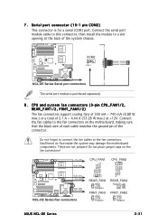
...These are not jumpers! Do not forget to connect the fan cables to the fan connectors on the fan connectors! 7 . Connect the serial port module cable to this connector, then install the module to a slot opening at the back of 2.1 A ~ 4.44 A (53.28 ... NCL-DE Series Fan connectors REAR_FAN1 GND +12V Rotation FRNT_FAN1 GND +12V Rotation REAR_FAN2 Rotation +12V GND FRNT_FAN2 GND +12V Rotation ASUS NCL-DE Series 2-31 Serial port connector (10-1 pin COM2) This connector is purchased separately. 8 . NCL-DE Series ® COM2 PIN 1 NCL-DE Series Serial port connectors The serial port ...
...These are not jumpers! Do not forget to connect the fan cables to the fan connectors on the fan connectors! 7 . Connect the serial port module cable to this connector, then install the module to a slot opening at the back of 2.1 A ~ 4.44 A (53.28 ... NCL-DE Series Fan connectors REAR_FAN1 GND +12V Rotation FRNT_FAN1 GND +12V Rotation REAR_FAN2 Rotation +12V GND FRNT_FAN2 GND +12V Rotation ASUS NCL-DE Series 2-31 Serial port connector (10-1 pin COM2) This connector is purchased separately. 8 . NCL-DE Series ® COM2 PIN 1 NCL-DE Series Serial port connectors The serial port ...
User Manual
Page 84
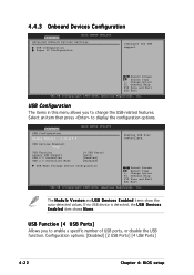
... Support USB 2.0 Controller USB 2.0 Controller Mode [4 USB Ports] [Auto] [Enabled] [HiSpeed] USB Mass Storage Device Configuration Select Screen Select Item +- USB Function [4 USB Ports] Allows you to enable a specific number of USB ports, or disable the USB function. 4.4.3 Onboard Devices Configuration Advanced... F10 Save and Exit ESC Exit v02.58 (C)Copyright 1985-2004, American Megatrends, Inc. Configuration options: [Disabled] [2 USB Ports] [4 USB Ports] 4-22 Chapter 4: BIOS setup USB Configuration The items in this menu allows you to change the USB-related features. If ...
... Support USB 2.0 Controller USB 2.0 Controller Mode [4 USB Ports] [Auto] [Enabled] [HiSpeed] USB Mass Storage Device Configuration Select Screen Select Item +- USB Function [4 USB Ports] Allows you to enable a specific number of USB ports, or disable the USB function. 4.4.3 Onboard Devices Configuration Advanced... F10 Save and Exit ESC Exit v02.58 (C)Copyright 1985-2004, American Megatrends, Inc. Configuration options: [Disabled] [2 USB Ports] [4 USB Ports] 4-22 Chapter 4: BIOS setup USB Configuration The items in this menu allows you to change the USB-related features. If ...
User Manual
Page 86
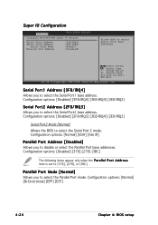
... Item +- Configuration options: [Normal] [Bi-Directional] [EPP] [ECP] 4-24 Chapter 4: BIOS setup Parallel Port Mode [Normal] Allows you to disable or select the Parallel Port base addresses. Change Option F1 General Help F10 Save and Exit ESC Exit v02.58 (C)Copyright 1985-2004, American...] [Normal] [Disabled] Allows BIOS to [378], [278], or [3BC]. Configuration options: [Normal] [IrDA] [Ask IR] Parallel Port Address [Disabled] Allows you to select the Serial Port 2 mode. Configuration options: [Disabled] [2F8/IRQ3] [3E8/IRQ4] [2E8/IRQ3] Serial Port2 Mode [Normal] Allows the BIOS to ...
... Item +- Configuration options: [Normal] [Bi-Directional] [EPP] [ECP] 4-24 Chapter 4: BIOS setup Parallel Port Mode [Normal] Allows you to disable or select the Parallel Port base addresses. Change Option F1 General Help F10 Save and Exit ESC Exit v02.58 (C)Copyright 1985-2004, American...] [Normal] [Disabled] Allows BIOS to [378], [278], or [3BC]. Configuration options: [Normal] [IrDA] [Ask IR] Parallel Port Address [Disabled] Allows you to select the Serial Port 2 mode. Configuration options: [Disabled] [2F8/IRQ3] [3E8/IRQ4] [2E8/IRQ3] Serial Port2 Mode [Normal] Allows the BIOS to ...
User Manual
Page 87
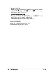
This item allows you to select the Parallel Port IRQ. [Configuration options: [IRQ5] [IRQ7] ASUS NCL-DE Series 4-25 Configuration options: [DMA0] [DMA1] [DMA3] Parallel Port IRQ [IRQ7] Allows you to set to E P P. EPP Version [1.9] Allows selection of the Parallel Port EPP version. Configuration options: [1.9] [1.7] ECP Mode DMA Channel [DMA3] Appears only when the Parallel Port Mode is set to [ECP]. This item appears only when the P a r a l l e l P o r t M o d e is set the Parallel Port ECP DMA.
This item allows you to select the Parallel Port IRQ. [Configuration options: [IRQ5] [IRQ7] ASUS NCL-DE Series 4-25 Configuration options: [DMA0] [DMA1] [DMA3] Parallel Port IRQ [IRQ7] Allows you to set to E P P. EPP Version [1.9] Allows selection of the Parallel Port EPP version. Configuration options: [1.9] [1.7] ECP Mode DMA Channel [DMA3] Appears only when the Parallel Port Mode is set to [ECP]. This item appears only when the P a r a l l e l P o r t M o d e is set the Parallel Port ECP DMA.
User Manual
Page 95
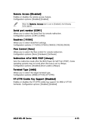
Configuration options: [COM1] [COM2] Baudrate [19200] Allows you to select Serial Port settings. Some operating systems may not work when this item is set to [Enabled], the following items appear. Configuration options: [Disabled] [Enabled] When the R e m ... Allows you to select the Serial Port for ANSI or VT100 terminals. Configuration options: [ANSI] [VT100] [VT-UTF8] VT-UTF8 Combo Key Support [Disabled] Enables or disables the VT-UTF8 combo key support for console redirection. Configuration options: [Disabled] [Enabled] ASUS NCL-DE Series 4-33 Configuration options: [Disabled...
Configuration options: [COM1] [COM2] Baudrate [19200] Allows you to select Serial Port settings. Some operating systems may not work when this item is set to [Enabled], the following items appear. Configuration options: [Disabled] [Enabled] When the R e m ... Allows you to select the Serial Port for ANSI or VT100 terminals. Configuration options: [ANSI] [VT100] [VT-UTF8] VT-UTF8 Combo Key Support [Disabled] Enables or disables the VT-UTF8 combo key support for console redirection. Configuration options: [Disabled] [Enabled] ASUS NCL-DE Series 4-33 Configuration options: [Disabled...
User Manual
Page 112
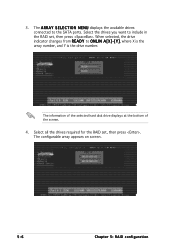
Select the drives you want to include in the RAID set , then press . The configurable array appears on screen. 5-6 Chapter 5: RAID configuration When selected, the drive indicator changes from R E A D Y to the SATA ports. Select all the drives required for the RAID set , then press . The A R R A Y S E L E C T I O N M E N U displays the available drives connected to ONLIN A[X]-[Y], where X is the array number, and Y is the drive number. 3. The information of the selected hard disk drive displays at the bottom of the screen. 4.
Select the drives you want to include in the RAID set , then press . The configurable array appears on screen. 5-6 Chapter 5: RAID configuration When selected, the drive indicator changes from R E A D Y to the SATA ports. Select all the drives required for the RAID set , then press . The A R R A Y S E L E C T I O N M E N U displays the available drives connected to ONLIN A[X]-[Y], where X is the array number, and Y is the drive number. 3. The information of the selected hard disk drive displays at the bottom of the screen. 4.
User Manual
Page 117
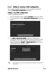
... configuration You can add a new RAID configuration or view an existing configuration using the V i e w / A d d C o n f i g u r a t i o n command. When selected, the drive indicator changes from R E A D Y to the SATA ports. ASUS NCL-DE Series 5-11 Select the drive(s) you want to select V i e w / A d d C o n f i g u r a t i o n, then press . 3. Use the arrow keys to include in the RAID set, then press . From the...
... configuration You can add a new RAID configuration or view an existing configuration using the V i e w / A d d C o n f i g u r a t i o n command. When selected, the drive indicator changes from R E A D Y to the SATA ports. ASUS NCL-DE Series 5-11 Select the drive(s) you want to select V i e w / A d d C o n f i g u r a t i o n, then press . 3. Use the arrow keys to include in the RAID set, then press . From the...
User Manual
Page 125
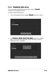
ASUS NCL-DE Series 5-19 The P H Y S I C A L D R I V E S S E L E C T I O N M E N U displays the available drives connected to rebuild, then press . To rebuild a failed hard disk drive: 1. Select the drive you want to the SATA ports. 5.2.4 Rebuilding failed drives You can manually rebuild failed hard disk drives using the R e b u i l d command in the Management Menu. From the Management Menu, highlight R e b u i l d, then press . 2.
ASUS NCL-DE Series 5-19 The P H Y S I C A L D R I V E S S E L E C T I O N M E N U displays the available drives connected to rebuild, then press . To rebuild a failed hard disk drive: 1. Select the drive you want to the SATA ports. 5.2.4 Rebuilding failed drives You can manually rebuild failed hard disk drives using the R e b u i l d command in the Management Menu. From the Management Menu, highlight R e b u i l d, then press . 2.
User Manual
Page 175
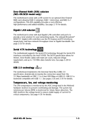
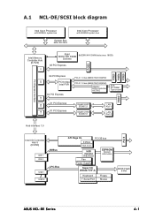
A.1 NCL-DE/SCSI block diagram PCIE3 PCIE4 PCIE5 Intel Xeon Processor with 800MHz system bus System Bus 64bit, 800 MHz Intel Xeon Processor with 800MHz system bus Intel ...-X 1.0 bus (64Bit/133(100)MHz) Adaptec SCSI-Controller AIC7902 ZCR SO-DIMM Type socket PCIE2 X1 PCI Express X1 PCI Express Gigabit LAN1 BCM5721 Gigabit LAN2 BCM5721 LAN Port 1 LAN Port 2 A1 B0 B1 Hub interface 1.5 PCI 6 Intel I /O W83627THF-A Keyboard 1st Serial Port Floppy Mouse BIOS Flash 8 Mbit ASUS NCL-DE Series A-1 H/W monitor W83792D Fan Power Supplly...
A.1 NCL-DE/SCSI block diagram PCIE3 PCIE4 PCIE5 Intel Xeon Processor with 800MHz system bus System Bus 64bit, 800 MHz Intel Xeon Processor with 800MHz system bus Intel ...-X 1.0 bus (64Bit/133(100)MHz) Adaptec SCSI-Controller AIC7902 ZCR SO-DIMM Type socket PCIE2 X1 PCI Express X1 PCI Express Gigabit LAN1 BCM5721 Gigabit LAN2 BCM5721 LAN Port 1 LAN Port 2 A1 B0 B1 Hub interface 1.5 PCI 6 Intel I /O W83627THF-A Keyboard 1st Serial Port Floppy Mouse BIOS Flash 8 Mbit ASUS NCL-DE Series A-1 H/W monitor W83792D Fan Power Supplly...
User Manual
Page 176
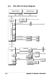
... EEPROM System information Super I /O Controller Hub 5 (ICH5R) IDE 1 IDE 2 SMBus USB 1 LPC-Bus USB 8 ATI Rage XL PCI 33 bus 8 Mbyte VGA-Conn. A.2 NCL-DE/1U block diagram Intel Xeon Processor with 800 MHz system bus System Bus 64bit, 800 MHz Intel Xeon Processor with 800 MHz system bus Intel... PCIE1 C A0 PCI Express interface A1 B0 B1 X1 PCI Express X1 PCI Express Hub interface 1.5 Gigabit LAN1 BCM5721 Gigabit LAN2 BCM5721 LAN Port 1 LAN Port 2 PCI 6 Intel I /O W83627THF-A Keyboard 1st Serial Port Floppy Mouse BIOS Flash 8 Mbit A-2 Appendix A: Reference information
... EEPROM System information Super I /O Controller Hub 5 (ICH5R) IDE 1 IDE 2 SMBus USB 1 LPC-Bus USB 8 ATI Rage XL PCI 33 bus 8 Mbyte VGA-Conn. A.2 NCL-DE/1U block diagram Intel Xeon Processor with 800 MHz system bus System Bus 64bit, 800 MHz Intel Xeon Processor with 800 MHz system bus Intel... PCIE1 C A0 PCI Express interface A1 B0 B1 X1 PCI Express X1 PCI Express Hub interface 1.5 Gigabit LAN1 BCM5721 Gigabit LAN2 BCM5721 LAN Port 1 LAN Port 2 PCI 6 Intel I /O W83627THF-A Keyboard 1st Serial Port Floppy Mouse BIOS Flash 8 Mbit A-2 Appendix A: Reference information