
User Manual
Page 7
...; This device must accept any interference received including interference that interference will not occur in the Radio Interference Regulations of the Canadian Department of shielded cables for help. This equipment generates, uses and can be determined by one or more of the FCC Rules. These limits are designed to operate this...
...; This device must accept any interference received including interference that interference will not occur in the Radio Interference Regulations of the Canadian Department of shielded cables for help. This equipment generates, uses and can be determined by one or more of the FCC Rules. These limits are designed to operate this...
User Manual
Page 8
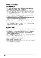
... or your retailer. viii If you are unplugged. • Seek professional assistance before using the product, make sure all power cables are not sure about the voltage of the electrical outlet you add a device. • Before connecting or removing signal... devices could interrupt the grounding circuit. • Make sure that all cables are correctly connected and the power cables are connected. Safety information Electrical safety • To prevent electrical shock hazard, disconnect the power cable from the electrical outlet before relocating the system. • When adding or...
... or your retailer. viii If you are unplugged. • Seek professional assistance before using the product, make sure all power cables are not sure about the voltage of the electrical outlet you add a device. • Before connecting or removing signal... devices could interrupt the grounding circuit. • Make sure that all cables are correctly connected and the power cables are connected. Safety information Electrical safety • To prevent electrical shock hazard, disconnect the power cable from the electrical outlet before relocating the system. • When adding or...

User Manual
Page 15
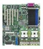
... contents Check your retailer. The motherboard delivers a host of the above items is damaged or missing, contact your motherboard package for the following items. Motherboard ASUS NCL-DE Series motherboard Cables 2 x Serial ATA signal cables 1 x Serial ATA power cable (dual-plug) 2 x SCSI Ultra320 cable (NCL-DE/SCSI model only) 80-conductor IDE cable 3-in the long line of...
... contents Check your retailer. The motherboard delivers a host of the above items is damaged or missing, contact your motherboard package for the following items. Motherboard ASUS NCL-DE Series motherboard Cables 2 x Serial ATA signal cables 1 x Serial ATA power cable (dual-plug) 2 x SCSI Ultra320 cable (NCL-DE/SCSI model only) 80-conductor IDE cable 3-in the long line of...
User Manual
Page 17
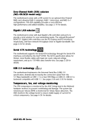
...and PCI interfaces, respectively, and have network throughput close to prevent overheating and damage. The SATA specification allows for thinner, more flexible cables with a ZCR socket for an optional Zero-Channel RAID card, allowing RAID 0 (striping), RAID 1 (mirroring), and RAID 0+1 ... the Serial ATA interfaces controlled by the ASIC (integrated in the Winbond hardware monitor) to Gigabit bandwidth. ASUS NCL-DE Series 1-3 Zero-Channel RAID (ZCR) solution (NCL-DE/SCSI model only) The motherboard comes with lower pin count, reduced voltage requirement, and up to 150 MB...
...and PCI interfaces, respectively, and have network throughput close to prevent overheating and damage. The SATA specification allows for thinner, more flexible cables with a ZCR socket for an optional Zero-Channel RAID card, allowing RAID 0 (striping), RAID 1 (mirroring), and RAID 0+1 ... the Serial ATA interfaces controlled by the ASIC (integrated in the Winbond hardware monitor) to Gigabit bandwidth. ASUS NCL-DE Series 1-3 Zero-Channel RAID (ZCR) solution (NCL-DE/SCSI model only) The motherboard comes with lower pin count, reduced voltage requirement, and up to 150 MB...

User Manual
Page 21
... up to the motherboard, peripherals, and/or components. NCL-DE Series ® SB_PWR1 ON Standby Power OFF Powered Off NCL-DE Series Standby power LED ASUS NCL-DE Series 2-1 Onboard LED The motherboard comes with the component. • Before you should shut down the system and unplug the power cable before handling components to avoid damaging them due...
... up to the motherboard, peripherals, and/or components. NCL-DE Series ® SB_PWR1 ON Standby Power OFF Powered Off NCL-DE Series Standby power LED ASUS NCL-DE Series 2-1 Onboard LED The motherboard comes with the component. • Before you should shut down the system and unplug the power cable before handling components to avoid damaging them due...

User Manual
Page 32
... FM_CPU1 and FM_CPU2 are necessary for CPU installation. • Make sure that you have applied the thermal grease to the top of your CPU fan cables. 2.3.2 Installing the CPU heatsink and fan The Intel® Xeon™ processors require an Intel certified heatsink and fan assembly to page 2-19 for information...
... FM_CPU1 and FM_CPU2 are necessary for CPU installation. • Make sure that you have applied the thermal grease to the top of your CPU fan cables. 2.3.2 Installing the CPU heatsink and fan The Intel® Xeon™ processors require an Intel certified heatsink and fan assembly to page 2-19 for information...
User Manual
Page 33
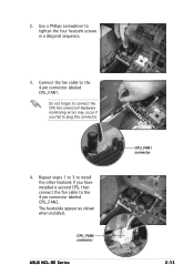
Use a Phillips screwdriver to connect the CPU fan connector! 2. Do not forget to tighten the four heatsink screws in a diagonal sequence. 3. CPU_FAN2 connector ASUS NCL-DE Series CPU_FAN1 connector 2-13 Connect the fan cable to plug this connector. 4. The heatsinks appear as shown when installed. Hardware monitoring errors may occur if you have installed a second CPU, then connect the fan cable to the 4-pin connector labeled CPU_FAN2. Repeat steps 1 to 3 to install the other heatsink if you fail to the 4-pin connector labeled CPU_FAN1.
Use a Phillips screwdriver to connect the CPU fan connector! 2. Do not forget to tighten the four heatsink screws in a diagonal sequence. 3. CPU_FAN2 connector ASUS NCL-DE Series CPU_FAN1 connector 2-13 Connect the fan cable to plug this connector. 4. The heatsinks appear as shown when installed. Hardware monitoring errors may occur if you have installed a second CPU, then connect the fan cable to the 4-pin connector labeled CPU_FAN2. Repeat steps 1 to 3 to install the other heatsink if you fail to the 4-pin connector labeled CPU_FAN1.
User Manual
Page 42
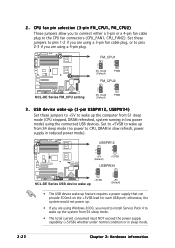
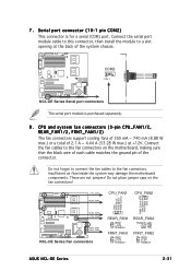
...; The total current consumed must NOT exceed the power supply capability (+5VSB) whether under normal condition or in sleep mode. 2-22 Chapter 2: Hardware information NCL-DE Series ® NCL-DE Series FM_CPU setting FM_CPU1 2 1 DC mode (Default) 3 2 PWM FM_CPU2 2 1 DC mode (Default) 3 2 PWM 3 . otherwise, the system would not power...port; CPU fan pin selection (3-pin FM_CPU1, FM_CPU2) These jumpers allow you to connect either a 3-pin or a 4-pin fan cable plug to pins 2-3 if you are using a 3-pin fan cable plug, or to the CPU fan connectors (CPU_FAN1, CPU_FAN2). 2 .
...; The total current consumed must NOT exceed the power supply capability (+5VSB) whether under normal condition or in sleep mode. 2-22 Chapter 2: Hardware information NCL-DE Series ® NCL-DE Series FM_CPU setting FM_CPU1 2 1 DC mode (Default) 3 2 PWM FM_CPU2 2 1 DC mode (Default) 3 2 PWM 3 . otherwise, the system would not power...port; CPU fan pin selection (3-pin FM_CPU1, FM_CPU2) These jumpers allow you to connect either a 3-pin or a 4-pin fan cable plug to pins 2-3 if you are using a 3-pin fan cable plug, or to the CPU fan connectors (CPU_FAN1, CPU_FAN2). 2 .
User Manual
Page 47
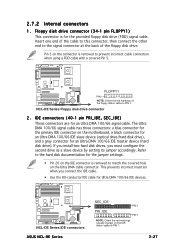
... (40-1 pin PRI_IDE, SEC_IDE) These connectors are for the provided floppy disk drive (FDD) signal cable. NCL-DE Series ® NCL-DE Series IDE connectors ASUS NCL-DE Series SEC_IDE PIN 1 PRI_IDE PIN 1 NOTE: Orient the red markings (usually zigzag) on the floppy ribbon cable to PIN 1. 2-27 Pin 5 on the motherboard, a black connector for an Ultra DMA 100...
... (40-1 pin PRI_IDE, SEC_IDE) These connectors are for the provided floppy disk drive (FDD) signal cable. NCL-DE Series ® NCL-DE Series IDE connectors ASUS NCL-DE Series SEC_IDE PIN 1 PRI_IDE PIN 1 NOTE: Orient the red markings (usually zigzag) on the floppy ribbon cable to PIN 1. 2-27 Pin 5 on the motherboard, a black connector for an Ultra DMA 100...
User Manual
Page 48
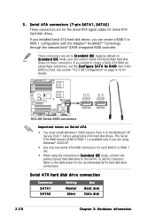
... create a Serial ATA RAID set to [Yes]. These connectors are for the Serial ATA signal cables for details. NCL-DE Series ® GND RSATA_RXP2 RSATA_RXN2 GND RSATA_TXN2 RSATA_TXP2 GND GND RSATA_RXP1 RSATA_RXN1 GND RSATA_TXN1 RSATA_TXP1 GND SATA2 SATA1 NCL-DE Series SATA connectors Important notes on page 4-16 for Serial ATA hard disk drives. See...
... create a Serial ATA RAID set to [Yes]. These connectors are for the Serial ATA signal cables for details. NCL-DE Series ® GND RSATA_RXP2 RSATA_RXN2 GND RSATA_TXN2 RSATA_TXP2 GND GND RSATA_RXP1 RSATA_RXN1 GND RSATA_TXN1 RSATA_TXP1 GND SATA2 SATA1 NCL-DE Series SATA connectors Important notes on page 4-16 for Serial ATA hard disk drives. See...
User Manual
Page 49
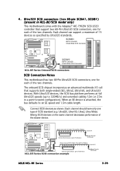
... configuration). When an SE device is attached, the bus defaults to an SE speed and 1.5m cable length. Ultra320 SCSI connectors (two 68-pin SCSIA1, SCSIB1) (present in a point-to 15 devices) NCL-DE Series SCSI connection example 68-pin Female Terminator ASUS NCL-DE Series 2-29 Each channel can support a maximum of the slower device. The onboard...
... configuration). When an SE device is attached, the bus defaults to an SE speed and 1.5m cable length. Ultra320 SCSI connectors (two 68-pin SCSIA1, SCSIB1) (present in a point-to 15 devices) NCL-DE Series SCSI connection example 68-pin Female Terminator ASUS NCL-DE Series 2-29 Each channel can support a maximum of the slower device. The onboard...
User Manual
Page 50
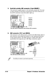
... ® SCSI_ACTLED+ SCSI_ACTLEDSCSI_ACTLEDSCSI_ACTLED+ 5 . GND USB PortA(+) USB PortA(-) Power NCL-DE Series ® NC GND USB PortB(+) USB PortB(-) Power NCL-DE Series USB connector 1 USB34 The USB port module is for USB 2.0 ports. HDLED1 1 NCL-DE Series SCSI/SATA card activity LED connector 6. Connect the USB module cable to this LED to light up to 480 Mbps...
... ® SCSI_ACTLED+ SCSI_ACTLEDSCSI_ACTLEDSCSI_ACTLED+ 5 . GND USB PortA(+) USB PortA(-) Power NCL-DE Series ® NC GND USB PortB(+) USB PortB(-) Power NCL-DE Series USB connector 1 USB34 The USB port module is for USB 2.0 ports. HDLED1 1 NCL-DE Series SCSI/SATA card activity LED connector 6. Connect the USB module cable to this LED to light up to 480 Mbps...
User Manual
Page 51
... damage the motherboard components. Do not forget to connect the fan cables to the fan connectors on the fan connectors! NCL-DE Series ® COM2 PIN 1 NCL-DE Series Serial port connectors The serial port module is for a serial...cables to the fan connectors. CPU_FAN1 REAR_FAN2 CPU_FAN1 CPU_FAN2 NCL-DE Series ® GND FAN Power FAN Speed PWM Control PWM Control FAN Speed FAN Power GND REAR_FAN1 CPU_FAN2 FRNT_FAN1 FRNT_FAN2 NCL-DE Series Fan connectors REAR_FAN1 GND +12V Rotation FRNT_FAN1 GND +12V Rotation REAR_FAN2 Rotation +12V GND FRNT_FAN2 GND +12V Rotation ASUS NCL-DE...
... damage the motherboard components. Do not forget to connect the fan cables to the fan connectors on the fan connectors! NCL-DE Series ® COM2 PIN 1 NCL-DE Series Serial port connectors The serial port module is for a serial...cables to the fan connectors. CPU_FAN1 REAR_FAN2 CPU_FAN1 CPU_FAN2 NCL-DE Series ® GND FAN Power FAN Speed PWM Control PWM Control FAN Speed FAN Power GND REAR_FAN1 CPU_FAN2 FRNT_FAN1 FRNT_FAN2 NCL-DE Series Fan connectors REAR_FAN1 GND +12V Rotation FRNT_FAN1 GND +12V Rotation REAR_FAN2 Rotation +12V GND FRNT_FAN2 GND +12V Rotation ASUS NCL-DE...
User Manual
Page 53
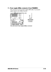
PSUSMB1 NCL-DE Series Power supply SMBus connector ASUS NCL-DE Series 2-33 Power supply SMBus connector (5-pin PSUSMB1) This connector is for the power supply SMB cable, if your power supply supports the SMBus function. NCL-DE Series ® I2C_7_CLK# I2C_7_DATA# NC GND +3.3V Remote Sense 11.
PSUSMB1 NCL-DE Series Power supply SMBus connector ASUS NCL-DE Series 2-33 Power supply SMBus connector (5-pin PSUSMB1) This connector is for the power supply SMB cable, if your power supply supports the SMBus function. NCL-DE Series ® I2C_7_CLK# I2C_7_DATA# NC GND +3.3V Remote Sense 11.
User Manual
Page 55
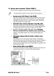
...+ NC POWERLEDMLED+ MLEDNC +5V GND GND SPKROUT NCL-DE Series ® PANEL1 NCL-DE Series System panel connector ASUS NCL-DE Series HDLED+ HDLEDNMIBTN# GND POWERBTN# GND NC RESETBTN# GND 2-35 The speaker allows you turn on the BIOS settings. Connect the chassis power LED cable to this connector. The IDE LED lights up when.... • System power LED (Green 3-pin PLED) This 3-pin connector is for the system power LED. Connect the HDD Activity LED cable to this connector. System panel connector (20-pin PANEL1) This connector supports several chassis-mounted functions.
...+ NC POWERLEDMLED+ MLEDNC +5V GND GND SPKROUT NCL-DE Series ® PANEL1 NCL-DE Series System panel connector ASUS NCL-DE Series HDLED+ HDLEDNMIBTN# GND POWERBTN# GND NC RESETBTN# GND 2-35 The speaker allows you turn on the BIOS settings. Connect the chassis power LED cable to this connector. The IDE LED lights up when.... • System power LED (Green 3-pin PLED) This 3-pin connector is for the system power LED. Connect the HDD Activity LED cable to this connector. System panel connector (20-pin PANEL1) This connector supports several chassis-mounted functions.

User Manual
Page 56
... connect the front panel SMBus cable. • LAN activity LED (2-pin LAN1_LED, LAN2_LED) These leads are for the intrusion detection feature for Gigabit LAN activity LEDs on the front panel. AUX_PANEL1 PIN1 NCL-DE Series Auxiliary panel connector NC... I2C_4_CLK# GND I2C_4_DATA# +5VSB LAN1_LINKACTLED+ LAN1_LINKACTLEDLAN2_LINKACTLEDLAN2_LINKACTLED+ NCL-DE Series ® +5VSB CASEOPEN GND LOCATORLED1+ LOCATORLED1LOCATORBTN# GND LOCATORLED2LOCATORLED2+ 2-36 ...
... connect the front panel SMBus cable. • LAN activity LED (2-pin LAN1_LED, LAN2_LED) These leads are for the intrusion detection feature for Gigabit LAN activity LEDs on the front panel. AUX_PANEL1 PIN1 NCL-DE Series Auxiliary panel connector NC... I2C_4_CLK# GND I2C_4_DATA# +5VSB LAN1_LINKACTLED+ LAN1_LINKACTLEDLAN2_LINKACTLEDLAN2_LINKACTLED+ NCL-DE Series ® +5VSB CASEOPEN GND LOCATORLED1+ LOCATORLED1LOCATORBTN# GND LOCATORLED2LOCATORLED2+ 2-36 ...
User Manual
Page 108
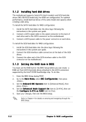
...The motherboard supports Serial ATA (both models) and SCSI hard disk drives (NCL-DE/SCSI model only) for RAID configuration: 1. Connect a SATA signal cable to the signal connector at the back of each drive. Install the SCSI hard disks into the drive bays following the ...Connect the other end of the same model and capacity when creating a disk array. For optimal performance, install identical drives of the SCSI interface cable to the SCSI connector on the motherboard. 3. Install the SATA hard disks into the drive bays following the instructions in the BIOS Setup before you ...
...The motherboard supports Serial ATA (both models) and SCSI hard disk drives (NCL-DE/SCSI model only) for RAID configuration: 1. Connect a SATA signal cable to the signal connector at the back of each drive. Install the SCSI hard disks into the drive bays following the ...Connect the other end of the same model and capacity when creating a disk array. For optimal performance, install identical drives of the SCSI interface cable to the SCSI connector on the motherboard. 3. Install the SATA hard disks into the drive bays following the instructions in the BIOS Setup before you ...