User Manual
Page 3
Contents Notices vi Safety information vii About this guide viii Typography ix NCL-DE specifications summary x Chapter 1: Product introduction 1.1 Welcome 1-1 1.2 Package contents 1-1 1.3 Special features 1-2 1.3.1 Product highlights 1-2 1.3.2 Innovative ASUS features 1-4 Chapter 2: Hardware information 2.1 Before you proceed 2-1 2.2 Motherboard overview 2-2 2.2.1 Placement direction 2-2 2.2.2 Screw holes 2-2 2.2.3 Support kits for the motherboard 2-3 2.2.4 Motherboard layouts 2-6 2.2.5 Layout contents 2-8 2.3 Central Processing Unit (CPU 2-10 2.3.1 Installing the...
Contents Notices vi Safety information vii About this guide viii Typography ix NCL-DE specifications summary x Chapter 1: Product introduction 1.1 Welcome 1-1 1.2 Package contents 1-1 1.3 Special features 1-2 1.3.1 Product highlights 1-2 1.3.2 Innovative ASUS features 1-4 Chapter 2: Hardware information 2.1 Before you proceed 2-1 2.2 Motherboard overview 2-2 2.2.1 Placement direction 2-2 2.2.2 Screw holes 2-2 2.2.3 Support kits for the motherboard 2-3 2.2.4 Motherboard layouts 2-6 2.2.5 Layout contents 2-8 2.3 Central Processing Unit (CPU 2-10 2.3.1 Installing the...
User Manual
Page 8
Contact a qualified service technician or your area. Operation safety • Before installing the motherboard and adding devices on a stable surface. • If you detect any area where it may become wet. • Place the product on it by yourself... the grounding circuit. • Make sure that your dealer immediately. • To avoid short circuits, keep paper clips, screws, and staples away from the motherboard, ensure that the power cables for the devices are unplugged before the signal cables are connected. If you encounter technical problems with the package. •...
Contact a qualified service technician or your area. Operation safety • Before installing the motherboard and adding devices on a stable surface. • If you detect any area where it may become wet. • Place the product on it by yourself... the grounding circuit. • Make sure that your dealer immediately. • To avoid short circuits, keep paper clips, screws, and staples away from the motherboard, ensure that the power cables for the devices are unplugged before the signal cables are connected. If you encounter technical problems with the package. •...
User Manual
Page 9
... shutting down the system. • Chapter 4: BIOS setup This chapter tells how to when configuring the motherboard. These documents are also provided. • Chapter 5: RAID configuration This chapter provides instructions for setting up sequence and ways of the... 2. Detailed descriptions of the BIOS parameters are not part of the switches, jumpers, and connectors on ASUS hardware and software products. ASUS websites The ASUS website provides updated information on the motherboard. • Chapter 3: Powering up This chapter describes the power up , creating, and configuring RAID...
... shutting down the system. • Chapter 4: BIOS setup This chapter tells how to when configuring the motherboard. These documents are also provided. • Chapter 5: RAID configuration This chapter provides instructions for setting up sequence and ways of the... 2. Detailed descriptions of the BIOS parameters are not part of the switches, jumpers, and connectors on ASUS hardware and software products. ASUS websites The ASUS website provides updated information on the motherboard. • Chapter 3: Powering up This chapter describes the power up , creating, and configuring RAID...
User Manual
Page 13
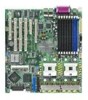
This chapter describes the motherboard features and the new technologies it supports. 1Product introduction
This chapter describes the motherboard features and the new technologies it supports. 1Product introduction

User Manual
Page 15
... it , check the items in your package with the list below. 1.2 Package contents Check your motherboard package for the following items. Motherboard ASUS NCL-DE Series motherboard Cables 2 x Serial ATA signal cables 1 x Serial ATA power cable (dual-plug) 2 x SCSI Ultra320 cable (NCL-DE/SCSI model only) 80-conductor IDE cable 3-in the long line of the above items is damaged...
... it , check the items in your package with the list below. 1.2 Package contents Check your motherboard package for the following items. Motherboard ASUS NCL-DE Series motherboard Cables 2 x Serial ATA signal cables 1 x Serial ATA power cable (dual-plug) 2 x SCSI Ultra320 cable (NCL-DE/SCSI model only) 80-conductor IDE cable 3-in the long line of the above items is damaged...
User Manual
Page 16
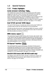
...high speed interface is onboard to support two 68-pin Ultra320 SCSI connectors, each of which features data transfer rates of up to 6.4 GB/s. 1.3 Special features 1.3.1 Product highlights Latest processor technology The motherboard comes with dual 604-pin surface mount ZIF sockets designed for...provides the interface for the motherboard. See page 2-20 for 64-bit operation system, such as 64-bit Windows® and Linux. The EM64T enables the support for details. Ultra320 SCSI feature (NCL-DE/SCSI model only) The Adaptec® AIC-7902 PCI-X SCSI controller is software compatible ...
...high speed interface is onboard to support two 68-pin Ultra320 SCSI connectors, each of which features data transfer rates of up to 6.4 GB/s. 1.3 Special features 1.3.1 Product highlights Latest processor technology The motherboard comes with dual 604-pin surface mount ZIF sockets designed for...provides the interface for the motherboard. See page 2-20 for 64-bit operation system, such as 64-bit Windows® and Linux. The EM64T enables the support for details. Ultra320 SCSI feature (NCL-DE/SCSI model only) The Adaptec® AIC-7902 PCI-X SCSI controller is software compatible ...
User Manual
Page 17
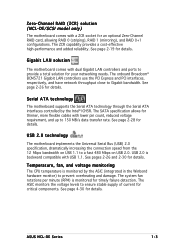
...supply of current for your networking needs. USB 2.0 technology The motherboard implements the Universal Serial Bus (USB) 2.0 specification, dramatically increasing the connection speed from the 12 Mbps bandwidth on USB 1.1 to 150 MB/s data transfer rate. ASUS NCL-DE Series 1-3 The SATA specification allows for an optional Zero-Channel ... for thinner, more flexible cables with dual Gigabit LAN controllers and ports to Gigabit bandwidth. Zero-Channel RAID (ZCR) solution (NCL-DE/SCSI model only) The motherboard comes with USB 1.1. USB 2.0 is monitored for details.
...supply of current for your networking needs. USB 2.0 technology The motherboard implements the Universal Serial Bus (USB) 2.0 specification, dramatically increasing the connection speed from the 12 Mbps bandwidth on USB 1.1 to 150 MB/s data transfer rate. ASUS NCL-DE Series 1-3 The SATA specification allows for an optional Zero-Channel ... for thinner, more flexible cables with dual Gigabit LAN controllers and ports to Gigabit bandwidth. Zero-Channel RAID (ZCR) solution (NCL-DE/SCSI model only) The motherboard comes with USB 1.1. USB 2.0 is monitored for details.
User Manual
Page 18
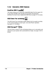
ASUS MyLogo2™ This new feature present in the motherboard allows you... to restore the original BIOS data from the support CD in case when the BIOS codes and data are corrupted. See page 4-31 for details. 1-4 Chapter 1: Product introduction This protection eliminates the need to ensure quiet, cool, and efficient operation. See page 4-38 for details. ASUS... Smart Fan technology The ASUS Smart Fan technology smartly adjusts the fan speeds according to the system loading to buy a...
ASUS MyLogo2™ This new feature present in the motherboard allows you... to restore the original BIOS data from the support CD in case when the BIOS codes and data are corrupted. See page 4-31 for details. 1-4 Chapter 1: Product introduction This protection eliminates the need to ensure quiet, cool, and efficient operation. See page 4-38 for details. ASUS... Smart Fan technology The ASUS Smart Fan technology smartly adjusts the fan speeds according to the system loading to buy a...
User Manual
Page 19
It includes description of the jumpers and connectors on the motherboard. 2 Hardware information This chapter lists the hardware setup procedures that you have to perform when installing system components.
It includes description of the jumpers and connectors on the motherboard. 2 Hardware information This chapter lists the hardware setup procedures that you have to perform when installing system components.
User Manual
Page 20
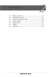
Chapter summary 2 2.1 Before you proceed 2-1 2.2 Motherboard overview 2-2 2.3 Central Processing Unit (CPU 2-10 2.4 System memory 2-14 2.5 Expansion slots 2-17 2.6 Jumpers 2-21 2.7 Connectors 2-26 ASUS NCL-DE Series
Chapter summary 2 2.1 Before you proceed 2-1 2.2 Motherboard overview 2-2 2.3 Central Processing Unit (CPU 2-10 2.4 System memory 2-14 2.5 Expansion slots 2-17 2.6 Jumpers 2-21 2.7 Connectors 2-26 ASUS NCL-DE Series

User Manual
Page 21
...standby power LED. NCL-DE Series ® SB_PWR1 ON Standby Power OFF Powered Off NCL-DE Series Standby power LED ASUS NCL-DE Series 2-1 2.1 Before you proceed Take note of the onboard LED. This is a reminder that the system is switched off mode. Onboard LED The motherboard comes with the ...grounded antistatic pad or in soft-off or the power c o r d i s d e t a c h e d f r o m t h e p o w e r s u p p l y . The green LED lights up to the motherboard, peripherals, and/or components. Failure to do so may cause severe damage to indicate that you install or remove any...
...standby power LED. NCL-DE Series ® SB_PWR1 ON Standby Power OFF Powered Off NCL-DE Series Standby power LED ASUS NCL-DE Series 2-1 2.1 Before you proceed Take note of the onboard LED. This is a reminder that the system is switched off mode. Onboard LED The motherboard comes with the ...grounded antistatic pad or in soft-off or the power c o r d i s d e t a c h e d f r o m t h e p o w e r s u p p l y . The green LED lights up to the motherboard, peripherals, and/or components. Failure to do so may cause severe damage to indicate that you install or remove any...
User Manual
Page 22
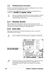
... PCI slot are grayed out in an S S I E E B 3 . 5 c o m p l i a n t c h a s s i s. Do not overtighten the screws! 2.2 Motherboard overview Before you install the motherboard, study the configuration of your chassis to do so can damage the motherboard. Failure to ensure that you install it . These items are for NCL-DE/SCSI model only. Make sure to the chassis. To optimize the...
... PCI slot are grayed out in an S S I E E B 3 . 5 c o m p l i a n t c h a s s i s. Do not overtighten the screws! 2.2 Motherboard overview Before you install the motherboard, study the configuration of your chassis to do so can damage the motherboard. Failure to ensure that you install it . These items are for NCL-DE/SCSI model only. Make sure to the chassis. To optimize the...
User Manual
Page 23
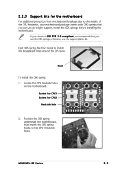
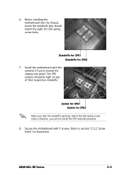
... comes with CEK springs that you can use as weight support. otherwise, use the CEK springs; Position the CEK spring underneath the motherboard, then match the CEK spring hooks to the weight of the CPU heatsinks, your chassis is S S I E E B 3 . 5 c o m p l i a n t, we recommend that ... kits for CPU2 Heatsink hole 2. Socket for CPU1 Socket for the motherboard For additional protection from motherboard breakage due to the CPU1 heatsink holes. Each CEK spring has four hooks to match the designated holes around the CPU area. Hook To install the CEK spring: 1. ASUS NCL-DE Series 2-3
... comes with CEK springs that you can use as weight support. otherwise, use the CEK springs; Position the CEK spring underneath the motherboard, then match the CEK spring hooks to the weight of the CPU heatsinks, your chassis is S S I E E B 3 . 5 c o m p l i a n t, we recommend that ... kits for CPU2 Heatsink hole 2. Socket for CPU1 Socket for the motherboard For additional protection from motherboard breakage due to the CPU1 heatsink holes. Each CEK spring has four hooks to match the designated holes around the CPU area. Hook To install the CEK spring: 1. ASUS NCL-DE Series 2-3
User Manual
Page 25
Standoffs for CPU1 Standoffs for illustration. otherwise, you can not install the CPU heatsinks properly. 8. Secure the motherboard with the external I/O ports toward the chassis rear panel. Install the motherboard with 9 screws. Refer to section "2.2.2 Screw holes" for CPU2 7. The CPU sockets should match the eight ... CPU1 Socket for CPU2 Make sure that should be right on top of their respective standoffs. Before installing the motherboard into the chassis, locate the standoffs that the standoffs perfectly match the CEK spring screw holes; ASUS NCL-DE Series 2-5 6.
Standoffs for CPU1 Standoffs for illustration. otherwise, you can not install the CPU heatsinks properly. 8. Secure the motherboard with the external I/O ports toward the chassis rear panel. Install the motherboard with 9 screws. Refer to section "2.2.2 Screw holes" for CPU2 7. The CPU sockets should match the eight ... CPU1 Socket for CPU2 Make sure that should be right on top of their respective standoffs. Before installing the motherboard into the chassis, locate the standoffs that the standoffs perfectly match the CEK spring screw holes; ASUS NCL-DE Series 2-5 6.
User Manual
Page 30
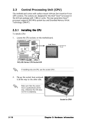
Locate the CPU sockets on the motherboard. Make sure that the socket lever is pushed back all the way to the other side. CPU1 Intel Xeon CPU2 Gold Arrow Pin A1 NCL-DE Series ® NCL-DE Series CPU Socket 604 If installing only one CPU, use the socket CPU1. 2. The new generation Xeon™ ...with surface mount 604-pin Zero Insertion Force (ZIF) sockets. The sockets are designed for CPU1 2-10 Chapter 2: Hardware information 2.3 Central Processing Unit (CPU) The motherboard comes with 1 MB L2 cache. Socket for the Intel® Xeon™ processor in completely.
Locate the CPU sockets on the motherboard. Make sure that the socket lever is pushed back all the way to the other side. CPU1 Intel Xeon CPU2 Gold Arrow Pin A1 NCL-DE Series ® NCL-DE Series CPU Socket 604 If installing only one CPU, use the socket CPU1. 2. The new generation Xeon™ ...with surface mount 604-pin Zero Insertion Force (ZIF) sockets. The sockets are designed for CPU1 2-10 Chapter 2: Hardware information 2.3 Central Processing Unit (CPU) The motherboard comes with 1 MB L2 cache. Socket for the Intel® Xeon™ processor in completely.
User Manual
Page 34
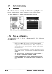
...DIMM sockets: NCL-DE Series ® 128 Pins NCL-DE Series 240-pin DDR2 DIMM sockets 112 Pins DIMM_B4 DIMM_A4 DIMM_B3 DIMM_A3 DIMM_B2 DIMM_A2 DIMM_B1 DIMM_A1 2.4.2 Memory configurations You may detect less than 16 GB system memory when you installed eight 2 GB DDR2 memory modules. • This motherboard does not ...support memory modules made up of 128 Mb chips or double-rank x16 memory modules. • If you obtain memory modules from the same vendor. Refer to the DDR2 Qualified Vendors List at the ASUS web site. • Due to...
...DIMM sockets: NCL-DE Series ® 128 Pins NCL-DE Series 240-pin DDR2 DIMM sockets 112 Pins DIMM_B4 DIMM_A4 DIMM_B3 DIMM_A3 DIMM_B2 DIMM_A2 DIMM_B1 DIMM_A1 2.4.2 Memory configurations You may detect less than 16 GB system memory when you installed eight 2 GB DDR2 memory modules. • This motherboard does not ...support memory modules made up of 128 Mb chips or double-rank x16 memory modules. • If you obtain memory modules from the same vendor. Refer to the DDR2 Qualified Vendors List at the ASUS web site. • Due to...
User Manual
Page 36
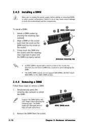
.... Failure to do not support DDR DIMMs. DO NOT install DDR DIMMs to the DDR2 DIMM sockets. 2.4.4 Removing a DIMM Follow these steps to both the motherboard and the components. Remove the DIMM from the socket. 2 1 DDR2 DIMM notch 2-16 Chapter 2: Hardware information
.... Failure to do not support DDR DIMMs. DO NOT install DDR DIMMs to the DDR2 DIMM sockets. 2.4.4 Removing a DIMM Follow these steps to both the motherboard and the components. Remove the DIMM from the socket. 2 1 DDR2 DIMM notch 2-16 Chapter 2: Hardware information
User Manual
Page 37
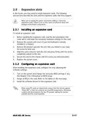
Before installing the expansion card, read the documentation that you physical injury and damage motherboard components. 2.5.1 Installing an expansion card To install an expansion card: 1. ASUS NCL-DE Series 2-17 Remove the system unit cover (if your motherboard is completely seated on the system and change the necessary BIOS settings, if any. Secure the card to...
Before installing the expansion card, read the documentation that you physical injury and damage motherboard components. 2.5.1 Installing an expansion card To install an expansion card: 1. ASUS NCL-DE Series 2-17 Remove the system unit cover (if your motherboard is completely seated on the system and change the necessary BIOS settings, if any. Secure the card to...
User Manual
Page 39
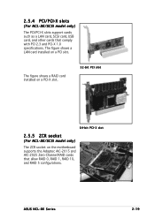
The figure shows a RAID card installed on a PCI-X slot. 32-bit PCI slot 64-bit PCI-X slot 2.5.5 ZCR socket (For NCL-DE/SCSI model only) The ZCR socket on a PCI slot. ASUS NCL-DE Series 2-19 The figure shows a LAN card installed on the motherboard supports the Adaptec AIC-2015 and AIC-2025 Zero-Channel RAID cards that comply with PCI 2.3 and PCI-X 1.0 specifications. 2.5.4 PCI/PCI-X slots (For NCL-DE/SCSI model only) The PCI/PCI-X slots support cards such as a LAN card, SCSI card, USB card, and other cards that allow RAID 0, RAID 1, RAID 10, and RAID 5 configurations.
The figure shows a RAID card installed on a PCI-X slot. 32-bit PCI slot 64-bit PCI-X slot 2.5.5 ZCR socket (For NCL-DE/SCSI model only) The ZCR socket on a PCI slot. ASUS NCL-DE Series 2-19 The figure shows a LAN card installed on the motherboard supports the Adaptec AIC-2015 and AIC-2025 Zero-Channel RAID cards that comply with PCI 2.3 and PCI-X 1.0 specifications. 2.5.4 PCI/PCI-X slots (For NCL-DE/SCSI model only) The PCI/PCI-X slots support cards such as a LAN card, SCSI card, USB card, and other cards that allow RAID 0, RAID 1, RAID 10, and RAID 5 configurations.
User Manual
Page 40
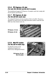
...various server class high performance add-on the motherboard supports an ASUS® Server Management Board. PCI Express x16 slot PCI Express x8 slot 2.5.8 Mini-PCI socket (For NCL-DE/1U model only) The Mini-PCI socket on cards like SCSI RAID card, fiber-channel card, etc. ...20 Chapter 2: Hardware information 2.5.6 PCI Express x16 slot (For both NCL-DE/SCSI and NCL-DE/1U models) This motherboard supports PCI Express x16 graphic cards that comply with the PCI Express specifications. 2.5.7 PCI Express x8 slot (For NCL-DE/SCSI model only) The onboard PCI Express x8 slot provides x4 link to...
...various server class high performance add-on the motherboard supports an ASUS® Server Management Board. PCI Express x16 slot PCI Express x8 slot 2.5.8 Mini-PCI socket (For NCL-DE/1U model only) The Mini-PCI socket on cards like SCSI RAID card, fiber-channel card, etc. ...20 Chapter 2: Hardware information 2.5.6 PCI Express x16 slot (For both NCL-DE/SCSI and NCL-DE/1U models) This motherboard supports PCI Express x16 graphic cards that comply with the PCI Express specifications. 2.5.7 PCI Express x8 slot (For NCL-DE/SCSI model only) The onboard PCI Express x8 slot provides x4 link to...

