User Manual
Page 4
... off the computer 3-2 3.2.1 Using the OS shut down function 3-2 3.2.2 Using the dual function power switch 3-2 Chapter 4: BIOS setup 4.1 Managing and updating your BIOS 4-1 4.1.1 Creating a bootable floppy disk 4-1 4.1.2 AFUDOS utility 4-2 4.1.3 ASUS CrashFree BIOS 2 utility 4-5 4.1.4 ASUS Update utility 4-7 4.2 BIOS setup program 4-10 4.2.1 BIOS menu screen 4-11 4.2.2 Menu bar 4-11 4.2.3 Navigation keys 4-11 4.2.4 Menu items 4-12 4.2.5 Sub-menu items 4-12...
... off the computer 3-2 3.2.1 Using the OS shut down function 3-2 3.2.2 Using the dual function power switch 3-2 Chapter 4: BIOS setup 4.1 Managing and updating your BIOS 4-1 4.1.1 Creating a bootable floppy disk 4-1 4.1.2 AFUDOS utility 4-2 4.1.3 ASUS CrashFree BIOS 2 utility 4-5 4.1.4 ASUS Update utility 4-7 4.2 BIOS setup program 4-10 4.2.1 BIOS menu screen 4-11 4.2.2 Menu bar 4-11 4.2.3 Navigation keys 4-11 4.2.4 Menu items 4-12 4.2.5 Sub-menu items 4-12...
User Manual
Page 5
... 5: RAID configuration 5.1 Setting up RAID 5-1 5.1.1 RAID definitions 5-1 5.1.2 Installing hard disk drives 5-2 5.1.3 Setting the RAID item in BIOS 5-2 5.1.4 RAID configuration utilities 5-3 5.2 LSI Logic Embedded SATA RAID Setup Utility 5-4 5.2.1 Creating a RAID set 5-5 5.2.2 Adding or viewing... RAID set 5-25 5.2.8 Enabling the WriteCache 5-26 5.3 Global Array Manager 5-26 5.4 Adaptec SCSISelect(TM) Utility! (NCL-DE/SCSI model only 5-27 5.4.1 Configuring the SCSI controller 5-28 5.4.2 Enabling the HostRAID controller 5-28 5.4.3 Creating a RAID 0 set (Stripe 5-29 5.4.4 Creating a...
... 5: RAID configuration 5.1 Setting up RAID 5-1 5.1.1 RAID definitions 5-1 5.1.2 Installing hard disk drives 5-2 5.1.3 Setting the RAID item in BIOS 5-2 5.1.4 RAID configuration utilities 5-3 5.2 LSI Logic Embedded SATA RAID Setup Utility 5-4 5.2.1 Creating a RAID set 5-5 5.2.2 Adding or viewing... RAID set 5-25 5.2.8 Enabling the WriteCache 5-26 5.3 Global Array Manager 5-26 5.4 Adaptec SCSISelect(TM) Utility! (NCL-DE/SCSI model only 5-27 5.4.1 Configuring the SCSI controller 5-28 5.4.2 Enabling the HostRAID controller 5-28 5.4.3 Creating a RAID 0 set (Stripe 5-29 5.4.4 Creating a...
User Manual
Page 9
.... • Chapter 2: Hardware information This chapter lists the hardware setup procedures that you have been added by your dealer. ix ASUS websites The ASUS website provides updated information on the motherboard. • Chapter 3: Powering up This chapter describes the power up , creating, and ... provides instructions for installing the necessary drivers for setting up sequence and ways of shutting down the system. • Chapter 4: BIOS setup This chapter tells how to when configuring the motherboard. About this guide is organized This user guide contains the following sources for...
.... • Chapter 2: Hardware information This chapter lists the hardware setup procedures that you have been added by your dealer. ix ASUS websites The ASUS website provides updated information on the motherboard. • Chapter 3: Powering up This chapter describes the power up , creating, and ... provides instructions for installing the necessary drivers for setting up sequence and ways of shutting down the system. • Chapter 4: BIOS setup This chapter tells how to when configuring the motherboard. About this guide is organized This user guide contains the following sources for...
User Manual
Page 12
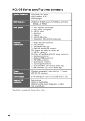
... Power Requirement Form Factor Support CD contents ASUS Smart Fan Control ASUS CrashFree BIOS 2 ASUS MyLogo2 AMI BIOS, 8 Mb FWH, Green, PnP, DMI2.0a, ACPI 2.0a SMBIOS 2.3, WfM2.0 1 x PS/2 keyboard port (purple) 1 x PS/2 mouse port (green) 2 x USB 2.0 ports 1 x Serial port 1 x VGA port 2 x LAN (RJ-45) ports 1 x Parallel port (NCL-DE/SCSI model only) 1 x Floppy disk drive connector 2 x IDE...
... Power Requirement Form Factor Support CD contents ASUS Smart Fan Control ASUS CrashFree BIOS 2 ASUS MyLogo2 AMI BIOS, 8 Mb FWH, Green, PnP, DMI2.0a, ACPI 2.0a SMBIOS 2.3, WfM2.0 1 x PS/2 keyboard port (purple) 1 x PS/2 mouse port (green) 2 x USB 2.0 ports 1 x Serial port 1 x VGA port 2 x LAN (RJ-45) ports 1 x Parallel port (NCL-DE/SCSI model only) 1 x Floppy disk drive connector 2 x IDE...
User Manual
Page 18
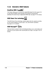
... feature present in the motherboard allows you to restore the original BIOS data from the support CD in case when the BIOS codes and data are corrupted. See page 4-31 for details. ASUS Smart Fan technology The ASUS Smart Fan technology smartly adjusts the fan speeds according to the ...system loading to buy a replacement ROM chip. 1.3.2 Innovative ASUS features CrashFree BIOS 2 This feature allows you ...
... feature present in the motherboard allows you to restore the original BIOS data from the support CD in case when the BIOS codes and data are corrupted. See page 4-31 for details. ASUS Smart Fan technology The ASUS Smart Fan technology smartly adjusts the fan speeds according to the ...system loading to buy a replacement ROM chip. 1.3.2 Innovative ASUS features CrashFree BIOS 2 This feature allows you ...
User Manual
Page 28
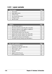
... BIOS recovery setting (3-pin RECOVERY1) Rear panel connectors 1. PS/2 keyboard port (purple) Page 2-10 2-14 2-19 2-19 2-20 2-20 Page 2-21 2-22 2-22 2-23 2-23 2-24 2-24 2-25 2-25 Page 2-26 2-26 2-26 2-26 2-26 2-26 2-26 2-8 Chapter 2: Hardware information SCSI controller setting (3-pin SCSI_EN1) 9. Clear RTC RAM (CLRTC1) 2. Parallel port (for NCL-DE...
... BIOS recovery setting (3-pin RECOVERY1) Rear panel connectors 1. PS/2 keyboard port (purple) Page 2-10 2-14 2-19 2-19 2-20 2-20 Page 2-21 2-22 2-22 2-23 2-23 2-24 2-24 2-25 2-25 Page 2-26 2-26 2-26 2-26 2-26 2-26 2-26 2-8 Chapter 2: Hardware information SCSI controller setting (3-pin SCSI_EN1) 9. Clear RTC RAM (CLRTC1) 2. Parallel port (for NCL-DE...
User Manual
Page 37
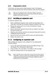
... IRQ" or that they support. Keep the screw for information on the system and change the necessary BIOS settings, if any. Align the card connector with it by adjusting the software settings. 1. Turn on BIOS setup. 2. Install the software drivers for the card. 2. Failure to the card. Replace the system cover. 2.5.2 Configuring.... Secure the card to the chassis with the screw you physical injury and damage motherboard components. 2.5.1 Installing an expansion card To install an expansion card: 1. ASUS NCL-DE Series 2-17
... IRQ" or that they support. Keep the screw for information on the system and change the necessary BIOS settings, if any. Align the card connector with it by adjusting the software settings. 1. Turn on BIOS setup. 2. Install the software drivers for the card. 2. Failure to the card. Replace the system cover. 2.5.2 Configuring.... Secure the card to the chassis with the screw you physical injury and damage motherboard components. 2.5.1 Installing an expansion card To install an expansion card: 1. ASUS NCL-DE Series 2-17
User Manual
Page 41
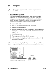
...the computer and unplug the power cord. 2. Plug the power cord and turn ON the computer. 6. NCL-DE Series ® NCL-DE Series Clear RTC RAM CLRTC1 21 32 Normal Clear CMOS (Default) ASUS NCL-DE Series 2-21 You can clear the CMOS memory of date, time, and system setup parameters by erasing... (default) to re-enter data. To erase the RTC RAM: 1. Hold down the key during the boot process and enter BIOS setup to pins 2-3. The onboard button cell battery powers the RAM data in NCL-DE/SCSI model. 1. Removing the cap will cause system boot failure! Remove the onboard battery. 3.
...the computer and unplug the power cord. 2. Plug the power cord and turn ON the computer. 6. NCL-DE Series ® NCL-DE Series Clear RTC RAM CLRTC1 21 32 Normal Clear CMOS (Default) ASUS NCL-DE Series 2-21 You can clear the CMOS memory of date, time, and system setup parameters by erasing... (default) to re-enter data. To erase the RTC RAM: 1. Hold down the key during the boot process and enter BIOS setup to pins 2-3. The onboard button cell battery powers the RAM data in NCL-DE/SCSI model. 1. Removing the cap will cause system boot failure! Remove the onboard battery. 3.
User Manual
Page 43
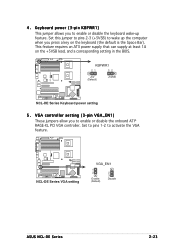
... lead, and a corresponding setting in the BIOS. Set to pins 1-2 to wake up feature. This feature requires an ATX power supply that can supply at least 1A on the keyboard (the default is the Space Bar). NCL-DE Series ® NCL-DE Series VGA setting VGA_EN1 1 2 Enable (Default) 2 3 Disable ASUS NCL-DE Series 2-23 Set this jumper to...
... lead, and a corresponding setting in the BIOS. Set to pins 1-2 to wake up feature. This feature requires an ATX power supply that can supply at least 1A on the keyboard (the default is the Space Bar). NCL-DE Series ® NCL-DE Series VGA setting VGA_EN1 1 2 Enable (Default) 2 3 Disable ASUS NCL-DE Series 2-23 Set this jumper to...

User Manual
Page 45
... SCSI feature, and support RAID configurations. SCSI controller setting (3-pin SCSI_EN1) (NCL-DE/SCSI model only) This jumper allows you to enable or disable the onboard Adaptec® AIC-7902W SCSI U320 controller. NCL-DE Series ® RECOVERY1 12 23 Normal BIOS Recovery (Default) NCL-DE Series BIOS recovery setting ASUS NCL-DE Series 2-25 Shut down the system. 5. To update the BIOS: 1. NCL-DE Series ® NCL-DE Series SCSI...
... SCSI feature, and support RAID configurations. SCSI controller setting (3-pin SCSI_EN1) (NCL-DE/SCSI model only) This jumper allows you to enable or disable the onboard Adaptec® AIC-7902W SCSI U320 controller. NCL-DE Series ® RECOVERY1 12 23 Normal BIOS Recovery (Default) NCL-DE Series BIOS recovery setting ASUS NCL-DE Series 2-25 Shut down the system. 5. To update the BIOS: 1. NCL-DE Series ® NCL-DE Series SCSI...
User Manual
Page 48
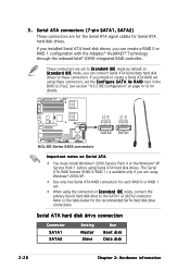
...in the BIOS to the SATA1 or SATA2 connector. In S t a n d a r d I D item in S t a n d a r d I D E mode by default. 3 . If you can create a RAID 0 or RAID 1 configuration with the Adaptec® HostRAID™ Technology through the onboard Intel® ICH5R integrated RAID controller. NCL-DE Series &#...174; GND RSATA_RXP2 RSATA_RXN2 GND RSATA_TXN2 RSATA_TXP2 GND GND RSATA_RXP1 RSATA_RXN1 GND RSATA_TXN1 RSATA_TXP1 GND SATA2 SATA1 NCL-DE Series SATA connectors Important notes on page 4-16 for the...
...in the BIOS to the SATA1 or SATA2 connector. In S t a n d a r d I D item in S t a n d a r d I D E mode by default. 3 . If you can create a RAID 0 or RAID 1 configuration with the Adaptec® HostRAID™ Technology through the onboard Intel® ICH5R integrated RAID controller. NCL-DE Series &#...174; GND RSATA_RXP2 RSATA_RXN2 GND RSATA_TXN2 RSATA_TXP2 GND GND RSATA_RXP1 RSATA_RXN1 GND RSATA_TXN1 RSATA_TXP1 GND SATA2 SATA1 NCL-DE Series SATA connectors Important notes on page 4-16 for the...
User Manual
Page 55
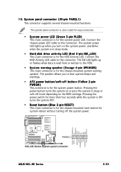
...) This connector is for the chassis-mounted reset button for the system power LED. Pressing the power button turns the system on the BIOS settings. The system panel connector is color-coded for easy connection. • System power LED (Green 3-pin PLED) This 3-pin ...flashes when data is for the chassis-mounted system warning speaker. POWERLED+ NC POWERLEDMLED+ MLEDNC +5V GND GND SPKROUT NCL-DE Series ® PANEL1 NCL-DE Series System panel connector ASUS NCL-DE Series HDLED+ HDLEDNMIBTN# GND POWERBTN# GND NC RESETBTN# GND 2-35 Pressing the power switch for more than four...
...) This connector is for the chassis-mounted reset button for the system power LED. Pressing the power button turns the system on the BIOS settings. The system panel connector is color-coded for easy connection. • System power LED (Green 3-pin PLED) This 3-pin ...flashes when data is for the chassis-mounted system warning speaker. POWERLED+ NC POWERLEDMLED+ MLEDNC +5V GND GND SPKROUT NCL-DE Series ® PANEL1 NCL-DE Series System panel connector ASUS NCL-DE Series HDLED+ HDLEDNMIBTN# GND POWERBTN# GND NC RESETBTN# GND 2-35 Pressing the power switch for more than four...
User Manual
Page 59
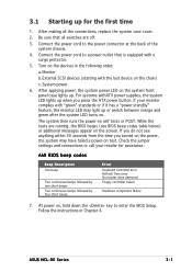
...system then runs the power-on . ASUS NCL-DE Series 3-1 After making all switches are running, the BIOS beeps (see anything within 30 seconds from the time you turned on the power, the system may light up when you do not see BIOS beep codes table below) or additional ...Time error No master drive detected Floppy controller failure Hardware component failure 7. Connect the power cord to enter the BIOS Setup. System power 6. At power on test. External SCSI devices (starting with a surge protector. 5. Check the jumper settings and connections or call your monitor complies ...
...system then runs the power-on . ASUS NCL-DE Series 3-1 After making all switches are running, the BIOS beeps (see anything within 30 seconds from the time you turned on the power, the system may light up when you do not see BIOS beep codes table below) or additional ...Time error No master drive detected Floppy controller failure Hardware component failure 7. Connect the power cord to enter the BIOS Setup. System power 6. At power on test. External SCSI devices (starting with a surge protector. 5. Check the jumper settings and connections or call your monitor complies ...
User Manual
Page 60
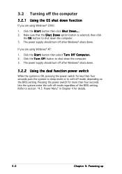
... Windows® XP: 1. Refer to shut down the computer. 3. The power supply should turn off mode, depending on the BIOS setting. Make sure that the S h u t D o w n option button is ON, pressing the power switch for ... seconds lets the system enter the soft-off after Windows® shuts down the computer. 3. The power supply should turn off mode regardless of the BIOS setting. Pressing the power switch for details. 3-2 Chapter 3: Powering up Click the S t a r t button then select T u r n O f f C o m p u t e r . 2. Click the S t a r t button then click S h u t D o w n...
... Windows® XP: 1. Refer to shut down the computer. 3. The power supply should turn off mode, depending on the BIOS setting. Make sure that the S h u t D o w n option button is ON, pressing the power switch for ... seconds lets the system enter the soft-off after Windows® shuts down the computer. 3. The power supply should turn off mode regardless of the BIOS setting. Pressing the power switch for details. 3-2 Chapter 3: Powering up Click the S t a r t button then select T u r n O f f C o m p u t e r . 2. Click the S t a r t button then click S h u t D o w n...
User Manual
Page 61
This chapter tells how to change the system settings through the BIOS Setup menus. Detailed descriptions of the BIOS parameters are also provided. 4 BIOS setup
This chapter tells how to change the system settings through the BIOS Setup menus. Detailed descriptions of the BIOS parameters are also provided. 4 BIOS setup
User Manual
Page 62
Chapter summary 4 4.1 Managing and updating your BIOS 4-1 4.2 BIOS setup program 4-10 4.3 Main menu 4-13 4.4 Advanced menu 4-18 4.5 Server menu 4-32 4.6 Security 4-34 4.7 Boot menu 4-37 4.8 Exit menu 4-40 ASUS NCL-DE Series
Chapter summary 4 4.1 Managing and updating your BIOS 4-1 4.2 BIOS setup program 4-10 4.3 Main menu 4-13 4.4 Advanced menu 4-18 4.5 Server menu 4-32 4.6 Security 4-34 4.7 Boot menu 4-37 4.8 Exit menu 4-40 ASUS NCL-DE Series
User Manual
Page 63
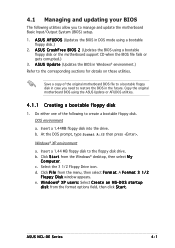
... sections for details on these utilities. Click F i l e from the format options field, then click S t a r t. A F o r m a t 3 1 / 2 F l o p p y D i s k window appears. ASUS NCL-DE Series 4-1 DOS environment a. At the DOS prompt, type format A:/S then press . d. e. Do either one of the original motherboard BIOS file to a bootable floppy disk in DOS mode using a bootable floppy disk.) 2. c. W i n d o w s® X P u s e r s : Select C r e a t e a n M S - Insert a 1.44MB...
... sections for details on these utilities. Click F i l e from the format options field, then click S t a r t. A F o r m a t 3 1 / 2 F l o p p y D i s k window appears. ASUS NCL-DE Series 4-1 DOS environment a. At the DOS prompt, type format A:/S then press . d. e. Do either one of the original motherboard BIOS file to a bootable floppy disk in DOS mode using a bootable floppy disk.) 2. c. W i n d o w s® X P u s e r s : Select C r e a t e a n M S - Insert a 1.44MB...
User Manual
Page 64
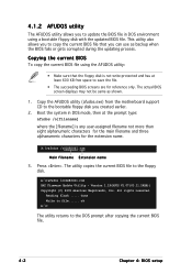
... you created earlier. 2. Boot the system in DOS environment using the AFUDOS utility: • Make sure that you to copy the current BIOS file that the floppy disk is any user-assigned filename not more than eight alphanumeric characters for the main filename and three alphanumeric characters for...has at least 600 KB free space to the floppy disk. Version 1.19(ASUS V2.07(03.11.24BB)) Copyright (C) 2002 American Megatrends, Inc. The actual BIOS screen displays may not be same as backup when the BIOS fails or gets corrupted during the updating process. Press . done Write to ...
... you created earlier. 2. Boot the system in DOS environment using the AFUDOS utility: • Make sure that you to copy the current BIOS file that the floppy disk is any user-assigned filename not more than eight alphanumeric characters for the main filename and three alphanumeric characters for...has at least 600 KB free space to the floppy disk. Version 1.19(ASUS V2.07(03.11.24BB)) Copyright (C) 2002 American Megatrends, Inc. The actual BIOS screen displays may not be same as backup when the BIOS fails or gets corrupted during the updating process. Press . done Write to ...
User Manual
Page 65
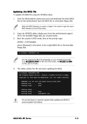
... O M for NCL-DE/SCSI model, and N C L D E 1 U . Do not turn off power during flash BIOS Reading file ....... N C L D E S C I . A:\>afudos /iNCLDESCI.ROM AMI Firmware Update Utility - Save the BIOS file to type the exact BIOS filename at the prompt...NCL-DE/1U model). 4. Visit the ASUS website (www.asus.com) and download the latest BIOS file for the motherboard. The utility verifies the file and starts updating the BIOS. done Reading flash ...... A:\>afudos /iNCLDESCI.rom Use the appropriate BIOS file depending on a piece of paper. ASUS NCL-DE Series 4-3 Updating the BIOS...
... O M for NCL-DE/SCSI model, and N C L D E 1 U . Do not turn off power during flash BIOS Reading file ....... N C L D E S C I . A:\>afudos /iNCLDESCI.ROM AMI Firmware Update Utility - Save the BIOS file to type the exact BIOS filename at the prompt...NCL-DE/1U model). 4. Visit the ASUS website (www.asus.com) and download the latest BIOS file for the motherboard. The utility verifies the file and starts updating the BIOS. done Reading flash ...... A:\>afudos /iNCLDESCI.rom Use the appropriate BIOS file depending on a piece of paper. ASUS NCL-DE Series 4-3 Updating the BIOS...
User Manual
Page 66
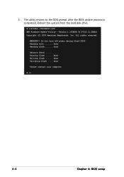
The utility returns to the DOS prompt after the BIOS update process is completed. Reboot the system from the hard disk drive. All rights reserved. Erasing flash ...... Do not turn off power during flash BIOS Reading file ....... done Writing flash ...... done Please restart your computer A:\> 4-4 Chapter 4: BIOS setup done Verifying flash .... WARNING!! 5. A:\>afudos /iNCLDESCI.ROM AMI Firmware Update Utility - Version 1.19(ASUS V2.07(03.11.24BB)) Copyright (C) 2002 American Megatrends, Inc. done Reading flash ...... done Advance Check ......
The utility returns to the DOS prompt after the BIOS update process is completed. Reboot the system from the hard disk drive. All rights reserved. Erasing flash ...... Do not turn off power during flash BIOS Reading file ....... done Writing flash ...... done Please restart your computer A:\> 4-4 Chapter 4: BIOS setup done Verifying flash .... WARNING!! 5. A:\>afudos /iNCLDESCI.ROM AMI Firmware Update Utility - Version 1.19(ASUS V2.07(03.11.24BB)) Copyright (C) 2002 American Megatrends, Inc. done Reading flash ...... done Advance Check ......
