User Manual
Page 5
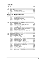
... a RAID configuration 5-11 5.2.3 Initializing the logical drives 5-14 5.2.4 Rebuilding failed drives 5-19 5.2.5 Checking the drives for data consistency 5-21 5.2.6 Deleting a RAID configuration 5-24 5.2.7 Selecting the boot drive from a RAID set 5-25 5.2.8 Enabling the WriteCache 5-26 5.3 Global Array Manager 5-26 5.4 Adaptec SCSISelect(TM) Utility! (NCL-DE/SCSI model only 5-27 5.4.1 Configuring the SCSI controller 5-28 5.4.2 Enabling the HostRAID controller...
... a RAID configuration 5-11 5.2.3 Initializing the logical drives 5-14 5.2.4 Rebuilding failed drives 5-19 5.2.5 Checking the drives for data consistency 5-21 5.2.6 Deleting a RAID configuration 5-24 5.2.7 Selecting the boot drive from a RAID set 5-25 5.2.8 Enabling the WriteCache 5-26 5.3 Global Array Manager 5-26 5.4 Adaptec SCSISelect(TM) Utility! (NCL-DE/SCSI model only 5-27 5.4.1 Configuring the SCSI controller 5-28 5.4.2 Enabling the HostRAID controller...
User Manual
Page 11
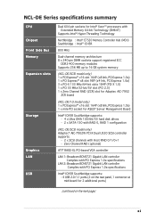
... link, PCI Express 1.0a) 1 x mini-PCI socket for ASUS® Server Management Board Intel® ICH5R Southbridge supports: - 4 x Ultra DMA 100/66/33 hard disk drives - 2 x SATA-150 with RAID 0, RAID 1 configuration (NCL-DE/SCSI model only) Adaptec® AIC-7902W PCI-X Dual U320 SCSI controller supports: - 2 x SCSI channels with PCI Express 1.0a specifications Intel® ICH5R...
... link, PCI Express 1.0a) 1 x mini-PCI socket for ASUS® Server Management Board Intel® ICH5R Southbridge supports: - 4 x Ultra DMA 100/66/33 hard disk drives - 2 x SATA-150 with RAID 0, RAID 1 configuration (NCL-DE/SCSI model only) Adaptec® AIC-7902W PCI-X Dual U320 SCSI controller supports: - 2 x SCSI channels with PCI Express 1.0a specifications Intel® ICH5R...
User Manual
Page 12
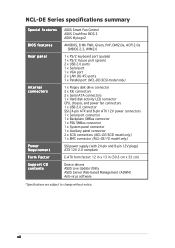
... Factor Support CD contents ASUS Smart Fan Control ASUS CrashFree BIOS 2 ASUS MyLogo2 AMI BIOS, 8 Mb FWH, Green, PnP, DMI2.0a, ACPI 2.0a SMBIOS 2.3, WfM2.0 1 x PS/2 keyboard port (purple) 1 x PS/2 mouse port (green) 2 x USB 2.0 ports 1 x Serial port 1 x VGA port 2 x LAN (RJ-45) ports 1 x Parallel port (NCL-DE/SCSI model only) 1 x Floppy disk drive connector 2 x IDE connectors 2 x Serial...
... Factor Support CD contents ASUS Smart Fan Control ASUS CrashFree BIOS 2 ASUS MyLogo2 AMI BIOS, 8 Mb FWH, Green, PnP, DMI2.0a, ACPI 2.0a SMBIOS 2.3, WfM2.0 1 x PS/2 keyboard port (purple) 1 x PS/2 mouse port (green) 2 x USB 2.0 ports 1 x Serial port 1 x VGA port 2 x LAN (RJ-45) ports 1 x Parallel port (NCL-DE/SCSI model only) 1 x Floppy disk drive connector 2 x IDE connectors 2 x Serial...

User Manual
Page 15
... missing, contact your motherboard package for buying an ASUS® NCL-DE Series motherboard! ASUS NCL-DE Series 1-1 The motherboard delivers a host of ASUS quality motherboards! 1.1 Welcome! Before you for the following items. Motherboard ASUS NCL-DE Series motherboard Cables 2 x Serial ATA signal cables 1 x Serial ATA power cable (dual-plug) 2 x SCSI Ultra320 cable (NCL-DE/SCSI model only) 80-conductor IDE cable 3-in the...
... missing, contact your motherboard package for buying an ASUS® NCL-DE Series motherboard! ASUS NCL-DE Series 1-1 The motherboard delivers a host of ASUS quality motherboards! 1.1 Welcome! Before you for the following items. Motherboard ASUS NCL-DE Series motherboard Cables 2 x Serial ATA signal cables 1 x Serial ATA power cable (dual-plug) 2 x SCSI Ultra320 cable (NCL-DE/SCSI model only) 80-conductor IDE cable 3-in the...
User Manual
Page 47
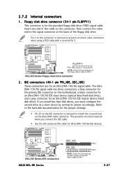
...three connectors: a blue connector for the primary IDE connector on the Ultra DMA cable connector. Insert one end of the floppy disk drive. NCL-DE Series ® FLOPPY1 PIN 1 NOTE: Orient the red markings on the floppy ribbon cable to match the covered hole on the ...) These connectors are for an Ultra DMA 100/66 IDE master device (hard disk drive). Floppy disk drive connector (34-1 pin FLOPPY1) This connector is removed to PIN 1. NCL-DE Series ® NCL-DE Series IDE connectors ASUS NCL-DE Series SEC_IDE PIN 1 PRI_IDE PIN 1 NOTE: Orient the red markings (usually zigzag)...
...three connectors: a blue connector for the primary IDE connector on the Ultra DMA cable connector. Insert one end of the floppy disk drive. NCL-DE Series ® FLOPPY1 PIN 1 NOTE: Orient the red markings on the floppy ribbon cable to match the covered hole on the ...) These connectors are for an Ultra DMA 100/66 IDE master device (hard disk drive). Floppy disk drive connector (34-1 pin FLOPPY1) This connector is removed to PIN 1. NCL-DE Series ® NCL-DE Series IDE connectors ASUS NCL-DE Series SEC_IDE PIN 1 PRI_IDE PIN 1 NOTE: Orient the red markings (usually zigzag)...
User Manual
Page 48
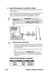
... to the SATA1 or SATA2 connector. In S t a n d a r d I D E mode by default. NCL-DE Series ® GND RSATA_RXP2 RSATA_RXN2 GND RSATA_TXN2 RSATA_TXP2 GND GND RSATA_RXP1 RSATA_RXN1 GND RSATA_TXN1 RSATA_TXP1 GND SATA2 SATA1 NCL-DE Series SATA connectors Important notes on page 4-16 for Serial ATA hard disk drives. These connectors are set the C o n f i g u r e S A T A As R A I D item in S t a n d a r d I D E mode...
... to the SATA1 or SATA2 connector. In S t a n d a r d I D E mode by default. NCL-DE Series ® GND RSATA_RXP2 RSATA_RXN2 GND RSATA_TXN2 RSATA_TXP2 GND GND RSATA_RXP1 RSATA_RXN1 GND RSATA_TXN1 RSATA_TXP1 GND SATA2 SATA1 NCL-DE Series SATA connectors Important notes on page 4-16 for Serial ATA hard disk drives. These connectors are set the C o n f i g u r e S A T A As R A I D item in S t a n d a r d I D E mode...
User Manual
Page 55
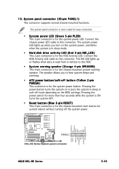
...or written to this connector. Pressing the power button turns the system on or puts the system in sleep mode. • Hard disk drive activity LED (Red 2-pin IDE_LED) This 2-pin connector is for the chassis-mounted reset button for the chassis-mounted system warning speaker. ... system power. The speaker allows you turn on the BIOS settings. POWERLED+ NC POWERLEDMLED+ MLEDNC +5V GND GND SPKROUT NCL-DE Series ® PANEL1 NCL-DE Series System panel connector ASUS NCL-DE Series HDLED+ HDLEDNMIBTN# GND POWERBTN# GND NC RESETBTN# GND 2-35 The IDE LED lights up when you to this ...
...or written to this connector. Pressing the power button turns the system on or puts the system in sleep mode. • Hard disk drive activity LED (Red 2-pin IDE_LED) This 2-pin connector is for the chassis-mounted reset button for the chassis-mounted system warning speaker. ... system power. The speaker allows you turn on the BIOS settings. POWERLED+ NC POWERLEDMLED+ MLEDNC +5V GND GND SPKROUT NCL-DE Series ® PANEL1 NCL-DE Series System panel connector ASUS NCL-DE Series HDLED+ HDLEDNMIBTN# GND POWERBTN# GND NC RESETBTN# GND 2-35 The IDE LED lights up when you to this ...
User Manual
Page 59
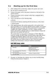
...the monitor LED may have failed a power-on the power, the system may light up for assistance. ASUS NCL-DE Series 3-1 Connect the power cord to enter the BIOS Setup. Monitor b. External SCSI devices (starting with a surge protector. 5. If your retailer for the first time 1. System power ...followed by two short beeps Two continuous beeps followed by four short beeps Error Keyboard controller error Refresh Time error No master drive detected Floppy controller failure Hardware component failure 7. If you do not see BIOS beep codes table below) or additional messages ...
...the monitor LED may have failed a power-on the power, the system may light up for assistance. ASUS NCL-DE Series 3-1 Connect the power cord to enter the BIOS Setup. Monitor b. External SCSI devices (starting with a surge protector. 5. If your retailer for the first time 1. System power ...followed by two short beeps Two continuous beeps followed by four short beeps Error Keyboard controller error Refresh Time error No master drive detected Floppy controller failure Hardware component failure 7. If you do not see BIOS beep codes table below) or additional messages ...
User Manual
Page 63
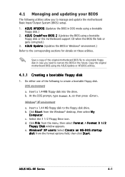
... Input/Output System (BIOS) setup. 1. Insert a 1.44 MB floppy disk to the floppy disk drive. Copy the original motherboard BIOS using a bootable floppy disk or the motherboard support CD when the BIOS file fails or gets corrupted.) 3. ASUS NCL-DE Series 4-1 Save a copy of the following utilities allow you need to restore the BIOS...
... Input/Output System (BIOS) setup. 1. Insert a 1.44 MB floppy disk to the floppy disk drive. Copy the original motherboard BIOS using a bootable floppy disk or the motherboard support CD when the BIOS file fails or gets corrupted.) 3. ASUS NCL-DE Series 4-1 Save a copy of the following utilities allow you need to restore the BIOS...
User Manual
Page 66
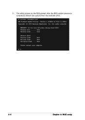
Reboot the system from the hard disk drive. done Verifying flash .... The utility returns to the DOS prompt after the BIOS update process is completed. Version 1.19(ASUS V2.07(03.11.24BB)) Copyright (C) 2002 American Megatrends, Inc. done Reading flash ...... done Writing flash ...... All rights reserved. WARNING!! Erasing flash ...... done Please restart your computer A:\> 4-4 Chapter 4: BIOS setup Do not turn off power during flash BIOS Reading file ....... A:\>afudos /iNCLDESCI.ROM AMI Firmware Update Utility - 5. done Advance Check ......
Reboot the system from the hard disk drive. done Verifying flash .... The utility returns to the DOS prompt after the BIOS update process is completed. Version 1.19(ASUS V2.07(03.11.24BB)) Copyright (C) 2002 American Megatrends, Inc. done Reading flash ...... done Writing flash ...... All rights reserved. WARNING!! Erasing flash ...... done Please restart your computer A:\> 4-4 Chapter 4: BIOS setup Do not turn off power during flash BIOS Reading file ....... A:\>afudos /iNCLDESCI.ROM AMI Firmware Update Utility - 5. done Advance Check ......
User Manual
Page 67
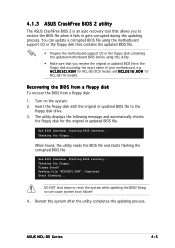
... the BIOS file and starts flashing the corrupted BIOS file. DO NOT shut down or reset the system while updating the BIOS! ASUS NCL-DE Series 4-5 Bad BIOS checksum. Starting BIOS recovery... You can cause system boot failure! 4. R O M for floppy... Recovering ... disk for NCL-DE/SCSI model, and N C L D E 1 U . N C L D E S C I . R O M for the original or updated BIOS file. Turn on the system. 2. Checking for floppy... Completed. 4.1.3 ASUS CrashFree BIOS 2 utility The ASUS CrashFree BIOS 2 is an auto recovery tool that you to the floppy disk drive. 3. Insert...
... the BIOS file and starts flashing the corrupted BIOS file. DO NOT shut down or reset the system while updating the BIOS! ASUS NCL-DE Series 4-5 Bad BIOS checksum. Starting BIOS recovery... You can cause system boot failure! 4. R O M for floppy... Recovering ... disk for NCL-DE/SCSI model, and N C L D E 1 U . N C L D E S C I . R O M for the original or updated BIOS file. Turn on the system. 2. Checking for floppy... Completed. 4.1.3 ASUS CrashFree BIOS 2 utility The ASUS CrashFree BIOS 2 is an auto recovery tool that you to the floppy disk drive. 3. Insert...

User Manual
Page 68
... the floppy disk for the original or updated BIOS file. When no floppy disk is found, the utility automatically checks the optical drive for the original or updated BIOS file. CD-ROM found ! Checking for CD-ROM... The utility then updates the corrupted BIOS ... system after the utility completes the updating process. Starting BIOS recovery... Starting BIOS recovery... Checking for this motherboard. Visit the ASUS website (www.asus.com) to the optical drive. 3. Bad BIOS checksum. The recovered BIOS may not be the latest BIOS version for floppy... Bad BIOS checksum. Floppy ...
... the floppy disk for the original or updated BIOS file. When no floppy disk is found, the utility automatically checks the optical drive for the original or updated BIOS file. CD-ROM found ! Checking for CD-ROM... The utility then updates the corrupted BIOS ... system after the utility completes the updating process. Starting BIOS recovery... Starting BIOS recovery... Checking for this motherboard. Visit the ASUS website (www.asus.com) to the optical drive. 3. Bad BIOS checksum. The recovered BIOS may not be the latest BIOS version for floppy... Bad BIOS checksum. Floppy ...
User Manual
Page 69
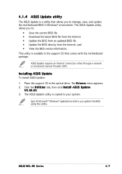
...and • View the BIOS version information. ASUS Update requires an Internet connection either through a network or an Internet Service Provider (ISP). X X. 3. ASUS NCL-DE Series 4-7 Installing ASUS Update To install ASUS Update: 1. Place the support CD in Windows...® environment. This utility is available in the support CD that allows you to your system. The ASUS Update utility is copied to manage, save, and update the motherboard BIOS in the optical drive. 4.1.4 ASUS...
...and • View the BIOS version information. ASUS Update requires an Internet connection either through a network or an Internet Service Provider (ISP). X X. 3. ASUS NCL-DE Series 4-7 Installing ASUS Update To install ASUS Update: 1. Place the support CD in Windows...® environment. This utility is available in the support CD that allows you to your system. The ASUS Update utility is copied to manage, save, and update the motherboard BIOS in the optical drive. 4.1.4 ASUS...
User Manual
Page 75
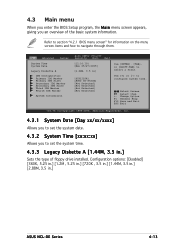
... Information BIOS SETUP UTILITY Security Boot Exit [11:10:19] [Mon 05/27/2005] [1.44M, 3.5 in .] ASUS NCL-DE Series 4-13 Configuration options: [Disabled] [360K, 5.25 in.] [1.2M , 5.25 in.] [720K , 3.5 in.] [1.44M, 3.5 in.] [2.88M, 3.5 in ] [ST32122A] [ASUS CD-S520A] [Not Detected] [Not Detected] [Not Detected] [Not Detected] Use [ENTER]. [TAB], or [SHIFT-TAB... and how to configure system time. 4.3 Main menu When you enter the BIOS Setup program, the M a i n menu screen appears, giving you an overview of floppy drive installed.
... Information BIOS SETUP UTILITY Security Boot Exit [11:10:19] [Mon 05/27/2005] [1.44M, 3.5 in .] ASUS NCL-DE Series 4-13 Configuration options: [Disabled] [360K, 5.25 in.] [1.2M , 5.25 in.] [720K , 3.5 in.] [1.44M, 3.5 in.] [2.88M, 3.5 in ] [ST32122A] [ASUS CD-S520A] [Not Detected] [Not Detected] [Not Detected] [Not Detected] Use [ENTER]. [TAB], or [SHIFT-TAB... and how to configure system time. 4.3 Main menu When you enter the BIOS Setup program, the M a i n menu screen appears, giving you an overview of floppy drive installed.
User Manual
Page 77
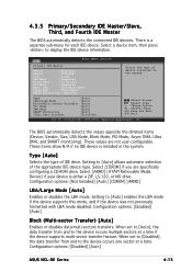
... Installed] [Auto] [CDROM] [ARMD] LBA/Large Mode [Auto] Enables or disables the LBA mode. Configuration options: [Disabled] [Auto] ASUS NCL-DE Series 4-15 4.3.5 Primary/Secondary IDE Master/Slave, Third, and Fourth IDE Master The BIOS automatically detects the connected IDE devices. Type [Auto...Monitoring: Supported Select the type of the appropriate IDE device type. These values are specifically configuring a CD-ROM drive. Type [Auto] Selects the type of IDE drive. Configuration options: [Disabled] [Auto] Block (Multi-sector Transfer) [Auto] Enables or disables data multi-sectors ...
... Installed] [Auto] [CDROM] [ARMD] LBA/Large Mode [Auto] Enables or disables the LBA mode. Configuration options: [Disabled] [Auto] ASUS NCL-DE Series 4-15 4.3.5 Primary/Secondary IDE Master/Slave, Third, and Fourth IDE Master The BIOS automatically detects the connected IDE devices. Type [Auto...Monitoring: Supported Select the type of the appropriate IDE device type. These values are specifically configuring a CD-ROM drive. Type [Auto] Selects the type of IDE drive. Configuration options: [Disabled] [Auto] Block (Multi-sector Transfer) [Auto] Enables or disables data multi-sectors ...

User Manual
Page 99
... Server Boot Device Priority 1st Boot Device 2nd Boot Device 3rd Boot Device BIOS SETUP UTILITY Security Boot Exit [1st FLOPPY DRIVE] [PS-ASUS CD-S520/A] [PM-ST32122A] Specifies the boot sequence from the available devices. Change Option F1 General Help F10 Save and...Inc. 1st ~ xxth Boot Device [1st FLOPPY DRIVE] 2nd Boot Device [xxx Drive] 3rd Boot Device [xxx Drive] These items specify the boot device priority sequence from the available devices. Select Screen Select Item +- Configuration options: [xxx Drive] [Disabled] ASUS NCL-DE Series 4-37 Select an item then press to ...
... Server Boot Device Priority 1st Boot Device 2nd Boot Device 3rd Boot Device BIOS SETUP UTILITY Security Boot Exit [1st FLOPPY DRIVE] [PS-ASUS CD-S520/A] [PM-ST32122A] Specifies the boot sequence from the available devices. Change Option F1 General Help F10 Save and...Inc. 1st ~ xxth Boot Device [1st FLOPPY DRIVE] 2nd Boot Device [xxx Drive] 3rd Boot Device [xxx Drive] These items specify the boot device priority sequence from the available devices. Select Screen Select Item +- Configuration options: [xxx Drive] [Disabled] ASUS NCL-DE Series 4-37 Select an item then press to ...
User Manual
Page 107
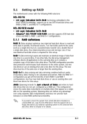
... advantage over using separate disks independently and does not provide fault tolerance or other drive. NCL-DE/SCSI model • LSI Logic Embedded SATA RAID • A d a p t e c® AIC-7902W SCSI RAID controller supports SCSI hard disk drives and RAID 0, RAID 1, and RAID 0+1 configurations. 5.1.1 RAID definitions R A... hard disk drive. Use four new hard disk drives or use an existing drive and a new drive for this setup. This RAID configuration provides data protection and increases fault tolerance to Chapter 6 for this setup. ASUS NCL-DE Series 5-1 Refer...
... advantage over using separate disks independently and does not provide fault tolerance or other drive. NCL-DE/SCSI model • LSI Logic Embedded SATA RAID • A d a p t e c® AIC-7902W SCSI RAID controller supports SCSI hard disk drives and RAID 0, RAID 1, and RAID 0+1 configurations. 5.1.1 RAID definitions R A... hard disk drive. Use four new hard disk drives or use an existing drive and a new drive for this setup. This RAID configuration provides data protection and increases fault tolerance to Chapter 6 for this setup. ASUS NCL-DE Series 5-1 Refer...
User Manual
Page 108
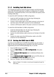
... motherboard supports Serial ATA (both models) and SCSI hard disk drives (NCL-DE/SCSI model only) for RAID configuration: 1. To do this: 1. Enter the BIOS Setup during POST. 2. Go to [Enhanced Mode], then press . 4. To install the SCSI hard disks for RAID set configuration. Set the O n b o a r d I D E O p e r a t e item to the M a i n M e n u, select I D item to [S-ATA], then set from...
... motherboard supports Serial ATA (both models) and SCSI hard disk drives (NCL-DE/SCSI model only) for RAID configuration: 1. To do this: 1. Enter the BIOS Setup during POST. 2. Go to [Enhanced Mode], then press . 4. To install the SCSI hard disks for RAID set configuration. Set the O n b o a r d I D E O p e r a t e item to the M a i n M e n u, select I D item to [S-ATA], then set from...
User Manual
Page 109
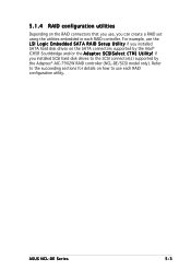
ASUS NCL-DE Series 5-3 Refer to the succeeding sections for details on the RAID connectors that you use, you can create a RAID set using the utilities embedded in each RAID configuration utility. For example, use the L S I L o g i c E m b e d d e d S A T A R A I D S e t u p U t i l i t y if you installed SCSI hard disk drives to the SCSI connector(s) supported by the Intel® ICH5R Southbridge and/or the...
ASUS NCL-DE Series 5-3 Refer to the succeeding sections for details on the RAID connectors that you use, you can create a RAID set using the utilities embedded in each RAID configuration utility. For example, use the L S I L o g i c E m b e d d e d S A T A R A I D S e t u p U t i l i t y if you installed SCSI hard disk drives to the SCSI connector(s) supported by the Intel® ICH5R Southbridge and/or the...
User Manual
Page 110
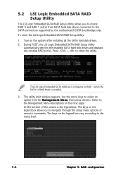
...the legend box allow you to create RAID 0 and RAID 1 set (s). The keys on the system after installing all the SATA hard disk drives. 2. 5.2 LSI Logic Embedded SATA RAID Setup Utility The LSI Logic Embedded SATA RAID Setup Utility allows you to navigate through the setup menu ... or execute commands. The utility main window appears. During POST, the LSI Logic Embedded SATA RAID Setup Utility automatically detects the installed SATA hard disk drives and displays any existing RAID set (s) from the M a n a g e m e n t M e n u, then press . Turn on the legend box vary according to RAID Mode...
...the legend box allow you to create RAID 0 and RAID 1 set (s). The keys on the system after installing all the SATA hard disk drives. 2. 5.2 LSI Logic Embedded SATA RAID Setup Utility The LSI Logic Embedded SATA RAID Setup Utility allows you to navigate through the setup menu ... or execute commands. The utility main window appears. During POST, the LSI Logic Embedded SATA RAID Setup Utility automatically detects the installed SATA hard disk drives and displays any existing RAID set (s) from the M a n a g e m e n t M e n u, then press . Turn on the legend box vary according to RAID Mode...