MAXIMUS VI EXTREME User's Manual
Page 3
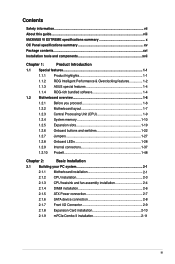
Contents Safety information...vii About this guide...viii MAXIMUS VI EXTREME specifications summary x OC Panel specifications summary xv Package contents...xvi Installation tools and components xvii Chapter 1: Product Introduction 1.1 Special features 1-1 1.1.1 Product highlights 1-1 1.1.2 ROG Intelligent Performance & Overclocking features 1-2 1.1.3 ASUS special features 1-4 1.1.4 ROG-rich bundled software 1-4 1.2 Motherboard overview 1-6 1.2.1 Before you proceed 1-6 1.2.2 Motherboard layout 1-7 1.2.3 Central Processing Unit...
Contents Safety information...vii About this guide...viii MAXIMUS VI EXTREME specifications summary x OC Panel specifications summary xv Package contents...xvi Installation tools and components xvii Chapter 1: Product Introduction 1.1 Special features 1-1 1.1.1 Product highlights 1-1 1.1.2 ROG Intelligent Performance & Overclocking features 1-2 1.1.3 ASUS special features 1-4 1.1.4 ROG-rich bundled software 1-4 1.2 Motherboard overview 1-6 1.2.1 Before you proceed 1-6 1.2.2 Motherboard layout 1-7 1.2.3 Central Processing Unit...

MAXIMUS VI EXTREME User's Manual
Page 7
... circuits, keep paper clips, screws, and staples away from connectors, slots, sockets and circuitry. • Avoid dust, humidity, and temperature extremes. If you add a device. • Before connecting or removing signal cables from the motherboard, ensure that all cables are correctly connected and the power cables are unplugged. • Seek professional assistance before...
... circuits, keep paper clips, screws, and staples away from connectors, slots, sockets and circuitry. • Avoid dust, humidity, and temperature extremes. If you add a device. • Before connecting or removing signal cables from the motherboard, ensure that all cables are correctly connected and the power cables are unplugged. • Seek professional assistance before...
MAXIMUS VI EXTREME User's Manual
Page 13
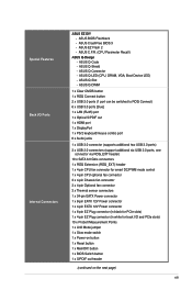
... 1 x 4-pin CPU optional fan connector 3 x 4-pin Chassis fan connector 3 x 4-pin Optional fan connector 3 x Thermal sensor connectors 1 x 24-pin EATX Power connector 1 x 8-pin EATX 12V Power connector 1 x 4-pin EATX 12V Power connector 1 x 6-pin EZ Plug connector (in black for PCIe slots) 1 x 4-pin EZ Plug connector (in white for back I /O Ports Internal Connectors ASUS EZ DIY - ASUS Q-Shield - ASUS C.P.R. (CPU Parameter Recall) ASUS Q-Design - ASUS Q-Connector - ASUS Q-Slot - Special Features Back I /O and...
... 1 x 4-pin CPU optional fan connector 3 x 4-pin Chassis fan connector 3 x 4-pin Optional fan connector 3 x Thermal sensor connectors 1 x 24-pin EATX Power connector 1 x 8-pin EATX 12V Power connector 1 x 4-pin EATX 12V Power connector 1 x 6-pin EZ Plug connector (in black for PCIe slots) 1 x 4-pin EZ Plug connector (in white for back I /O Ports Internal Connectors ASUS EZ DIY - ASUS Q-Shield - ASUS C.P.R. (CPU Parameter Recall) ASUS Q-Design - ASUS Q-Connector - ASUS Q-Slot - Special Features Back I /O and...
MAXIMUS VI EXTREME User's Manual
Page 15
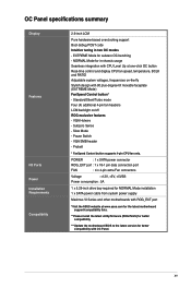
EXTREME Mode for NORMAL Mode installation 1 x SATA power cable from system power supply Maximus VI Series and other motherboards with ROG_EXT port *Visit the ASUS website at one-click OC button Real-time control and display CPU fan speed, temperature, BCLK and ... compatibility with 90 plus-degree-tilt movable faceplate (EXTREME Mode) FanSpeed Control button* - NORMAL Mode for in two OC modes - POWER : 1 x SATA power connector ROG_EXT port : 1 x 18-1 pin data connection port FAN : 4 x 4-pin extra Fan connectors Voltage : +12V, +5V, +5VSB Power consumption : 5A 1 x 5.25-inch drive ...
EXTREME Mode for NORMAL Mode installation 1 x SATA power cable from system power supply Maximus VI Series and other motherboards with ROG_EXT port *Visit the ASUS website at one-click OC button Real-time control and display CPU fan speed, temperature, BCLK and ... compatibility with 90 plus-degree-tilt movable faceplate (EXTREME Mode) FanSpeed Control button* - NORMAL Mode for in two OC modes - POWER : 1 x SATA power connector ROG_EXT port : 1 x 18-1 pin data connection port FAN : 4 x 4-pin extra Fan connectors Voltage : +12V, +5V, +5VSB Power consumption : 5A 1 x 5.25-inch drive ...
MAXIMUS VI EXTREME User's Manual
Page 20
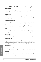
.... DIMM Post, quickly and easily check your desktop PC and tweak its parameters in real-time via the proprietary connector onboard. Extreme Engine Digi+ III The Extreme Engine Digi+ III offers the best CPU/Memory design on -the-fly parameter adjustments at a purely hardware level....BIOS Print that fully maximizes ROG's unique functions, providing you want to overclock to 90% efficiency under extreme conditions. iROG The iROG is equipped with NexFETTM Power Block MOSFET that you with the press of your graphic cards, memory modules' statuses in detecting component ...
.... DIMM Post, quickly and easily check your desktop PC and tweak its parameters in real-time via the proprietary connector onboard. Extreme Engine Digi+ III The Extreme Engine Digi+ III offers the best CPU/Memory design on -the-fly parameter adjustments at a purely hardware level....BIOS Print that fully maximizes ROG's unique functions, providing you want to overclock to 90% efficiency under extreme conditions. iROG The iROG is equipped with NexFETTM Power Block MOSFET that you with the press of your graphic cards, memory modules' statuses in detecting component ...
MAXIMUS VI EXTREME User's Manual
Page 26
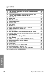
... 1-46 1-40 1-47 1-26 1-25 1-42 1-39 1-45 1-46 Chapter 1 1-8 Chapter 1: Product introduction LN2 Mode header 14. USB 2.0 connectors (10-1 pin USB910; DirectKey button 22. PCIe x16 Lane switch 7. START (Power-on) button 8. Front panel audio connector (10-1 pin AAFP) 24. Power connectors (24-pin EATXPWR, 8-pin EATX12V, 4-pin EATX12V) 2. CPU, chassis, and optional fan...
... 1-46 1-40 1-47 1-26 1-25 1-42 1-39 1-45 1-46 Chapter 1 1-8 Chapter 1: Product introduction LN2 Mode header 14. USB 2.0 connectors (10-1 pin USB910; DirectKey button 22. PCIe x16 Lane switch 7. START (Power-on) button 8. Front panel audio connector (10-1 pin AAFP) 24. Power connectors (24-pin EATXPWR, 8-pin EATX12V, 4-pin EATX12V) 2. CPU, chassis, and optional fan...

MAXIMUS VI EXTREME User's Manual
Page 38
x8 (Native) - - x8 x8 - - x16 x16 PCIe 3.0/2.0_x8_B2 - x8 • We recommend that you provide sufficient power when running CrossFireX™ or SLI® mode. • Connect a chassis fan to the motherboard connector labeled CHA_FAN1-3 when using multiple graphics cards for better thermal environment. • 4th generation Intel® Core™ processors support...
x8 (Native) - - x8 x8 - - x16 x16 PCIe 3.0/2.0_x8_B2 - x8 • We recommend that you provide sufficient power when running CrossFireX™ or SLI® mode. • Connect a chassis fan to the motherboard connector labeled CHA_FAN1-3 when using multiple graphics cards for better thermal environment. • 4th generation Intel® Core™ processors support...
MAXIMUS VI EXTREME User's Manual
Page 56
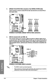
...install the related driver to Serial ATA 6.0 Gb/s hard disk drives via Serial ATA 6.0 Gb/s signal cables. 4. USB 3.0 connector (20-1 pin USB3_12) This connector allows you can enjoy all the benefits of USB 3.0 including faster data transfer speeds of up to connect a USB 3.0 module... for USB-chargeable devices, optimized power efficiency, and backward compatibility with USB 2.0. • The USB 3.0 module is purchased separately. • These connectors are based on xHCI specification. With an installed USB 3.0 module, you to 5Gbps, ...
...install the related driver to Serial ATA 6.0 Gb/s hard disk drives via Serial ATA 6.0 Gb/s signal cables. 4. USB 3.0 connector (20-1 pin USB3_12) This connector allows you can enjoy all the benefits of USB 3.0 including faster data transfer speeds of up to connect a USB 3.0 module... for USB-chargeable devices, optimized power efficiency, and backward compatibility with USB 2.0. • The USB 3.0 module is purchased separately. • These connectors are based on xHCI specification. With an installed USB 3.0 module, you to 5Gbps, ...

MAXIMUS VI EXTREME User's Manual
Page 59
...wire of each cable matches the ground pin of maximum 1A (12 W) fan power. • The CPU_FAN connector and CHA_FAN connectors support the ASUS FAN Xpert 2 feature. • The CPU fan connector has a special latch that detects the installed CPU fan type and automatically changes... the fan cables to the fan connectors on the fan connectors! • Ensure to fully insert the 4-pin CPU fan cable to the CPU fan connector. • The CPU_FAN connector supports the CPU fan of the connector. ASUS MAXIMUS VI EXTREME 1-41 CPU, chassis, and optional fan connectors (4-pin CPU_FAN; 4-pin CPU_OPT; ...
...wire of each cable matches the ground pin of maximum 1A (12 W) fan power. • The CPU_FAN connector and CHA_FAN connectors support the ASUS FAN Xpert 2 feature. • The CPU fan connector has a special latch that detects the installed CPU fan type and automatically changes... the fan cables to the fan connectors on the fan connectors! • Ensure to fully insert the 4-pin CPU fan cable to the CPU fan connector. • The CPU_FAN connector supports the CPU fan of the connector. ASUS MAXIMUS VI EXTREME 1-41 CPU, chassis, and optional fan connectors (4-pin CPU_FAN; 4-pin CPU_OPT; ...
MAXIMUS VI EXTREME User's Manual
Page 61
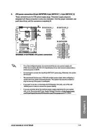
ASUS MAXIMUS VI EXTREME 1-43 Chapter 1 Otherwise, the system will not boot. • We recommend that complies with ATX 12 V Specification 2.0 (or later version) and provides a minimum power of 350 W. • Do not forget to the Recommended Power Supply Wattage Calculator at http://support.asus. Find the proper orientation and push down firmly until the connectors completely fit. •...
ASUS MAXIMUS VI EXTREME 1-43 Chapter 1 Otherwise, the system will not boot. • We recommend that complies with ATX 12 V Specification 2.0 (or later version) and provides a minimum power of 350 W. • Do not forget to the Recommended Power Supply Wattage Calculator at http://support.asus. Find the proper orientation and push down firmly until the connectors completely fit. •...
MAXIMUS VI EXTREME User's Manual
Page 62
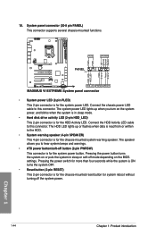
...the system in sleep mode. • Hard disk drive activity LED (2-pin HDD_LED) This 2-pin connector is for the HDD Activity LED. Connect the chassis power LED cable to this connector. The system power LED lights up or flashes when data is read from or written to hear system beeps and warnings...is ON turns the system OFF. • Reset button (2-pin RESET) This 2-pin connector is for the chassis-mounted reset button for system reboot without turning off button (2-pin PWRSW) This connector is for the system power button. The HDD LED lights up when you to the HDD. • System ...
...the system in sleep mode. • Hard disk drive activity LED (2-pin HDD_LED) This 2-pin connector is for the HDD Activity LED. Connect the chassis power LED cable to this connector. The system power LED lights up or flashes when data is read from or written to hear system beeps and warnings...is ON turns the system OFF. • Reset button (2-pin RESET) This 2-pin connector is for the chassis-mounted reset button for system reboot without turning off button (2-pin PWRSW) This connector is for the system power button. The HDD LED lights up when you to the HDD. • System ...
MAXIMUS VI EXTREME User's Manual
Page 63
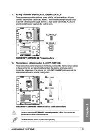
EZ Plug connectors (6-pin EZ_PLUG_1; 4-pin EZ_PLUG_2) These connectors provide additional power to the back IO ports. 12. Thermal sensor cable connectors (2-pin OPT_TEMP1/2/3) These connectors are purchased separately. The optional fan 1/2/3 (OPT_FAN1/2/3) can work with the temperature sensors for temperature monitoring. The thermal sensor cables are for a better cooling effect. ASUS MAXIMUS VI EXTREME 1-45 Connect a 4-pin power cable to...
EZ Plug connectors (6-pin EZ_PLUG_1; 4-pin EZ_PLUG_2) These connectors provide additional power to the back IO ports. 12. Thermal sensor cable connectors (2-pin OPT_TEMP1/2/3) These connectors are purchased separately. The optional fan 1/2/3 (OPT_FAN1/2/3) can work with the temperature sensors for temperature monitoring. The thermal sensor cables are for a better cooling effect. ASUS MAXIMUS VI EXTREME 1-45 Connect a 4-pin power cable to...
MAXIMUS VI EXTREME User's Manual
Page 87
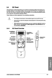
... Up OC Start Start Button Value up Button LOeK ft Arrow button Clear CleaResret button Fan connectors 1,2 VGA Hotwire connectors Start OK Clear Reset ON ON OFF OFF Power Button FanSpeed Control button OK button Right Arrow button Reset button Value Down button Fan connectors 3,4 OC Start Subzero Sense connector OK Clear Reset Chapter 2 ASUS MAXIMUS VI EXTREME 2-21
... Up OC Start Start Button Value up Button LOeK ft Arrow button Clear CleaResret button Fan connectors 1,2 VGA Hotwire connectors Start OK Clear Reset ON ON OFF OFF Power Button FanSpeed Control button OK button Right Arrow button Reset button Value Down button Fan connectors 3,4 OC Start Subzero Sense connector OK Clear Reset Chapter 2 ASUS MAXIMUS VI EXTREME 2-21

MAXIMUS VI EXTREME User's Manual
Page 90
...assembly into the OC Panel 5.25-inch drive bay metal case. 5. Open your computer. 12. Press the OC Panel power button to the OC Panel. 10. Locate the ROG_EXT connector on the OC Panel LCM display. 2-24 Chapter 2: Basic Installation Ensure that the OC Panel fits snugly into the drive... bay. 8. Connect the OC Panel data cable (A) and a SATA Power cable (B) to turn on the motherboard and connect the OC ...
...assembly into the OC Panel 5.25-inch drive bay metal case. 5. Open your computer. 12. Press the OC Panel power button to the OC Panel. 10. Locate the ROG_EXT connector on the OC Panel LCM display. 2-24 Chapter 2: Basic Installation Ensure that the OC Panel fits snugly into the drive... bay. 8. Connect the OC Panel data cable (A) and a SATA Power cable (B) to turn on the motherboard and connect the OC ...

MAXIMUS VI EXTREME User's Manual
Page 91
...: 1. Connect the OC Panel cable (A) and a SATA Power cable (B) to turn on the motherboard and connect the OC Panel cable. ASUS MAXIMUS VI EXTREME 2-25 To setup the OC Panel in Extreme Mode, you can enjoy more features including Subzero Sense and VGA Hotwire. Locate the ROG_EXT connector on the OC Panel LCM display. Chapter 2 4. 2.4.3 Setting up...
...: 1. Connect the OC Panel cable (A) and a SATA Power cable (B) to turn on the motherboard and connect the OC Panel cable. ASUS MAXIMUS VI EXTREME 2-25 To setup the OC Panel in Extreme Mode, you can enjoy more features including Subzero Sense and VGA Hotwire. Locate the ROG_EXT connector on the OC Panel LCM display. Chapter 2 4. 2.4.3 Setting up...
MAXIMUS VI EXTREME User's Manual
Page 92
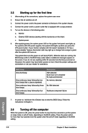
... No keyboard detected No memory detected No VGA detected Hardware component failure 7. The system then runs the power-on test. If you do not see anything within 30 seconds from orange to the power connector at the back of the BIOS setting. BIOS Beep One short beep One continuous beep followed by two...
... No keyboard detected No memory detected No VGA detected Hardware component failure 7. The system then runs the power-on test. If you do not see anything within 30 seconds from orange to the power connector at the back of the BIOS setting. BIOS Beep One short beep One continuous beep followed by two...
MAXIMUS VI EXTREME User's Manual
Page 192
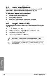
... the RAID item in BIOS You must enable the RAID function in the BIOS Setup before creating RAID sets using SATA HDDs. Connect a SATA power cable to the power connector on entering and navigating through the BIOS Setup Due to chipset limitation, when SATA ports are set to Chapter 3 for a RAID configuration: 1. Go...
... the RAID item in BIOS You must enable the RAID function in the BIOS Setup before creating RAID sets using SATA HDDs. Connect a SATA power cable to the power connector on entering and navigating through the BIOS Setup Due to chipset limitation, when SATA ports are set to Chapter 3 for a RAID configuration: 1. Go...


