MAXIMUS VI EXTREME User's Manual
Page 3
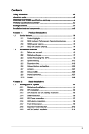
... guide...viii MAXIMUS VI EXTREME specifications summary x OC Panel specifications summary xv Package contents...xvi Installation tools and components xvii Chapter 1: Product Introduction 1.1 Special features 1-1 1.1.1 Product highlights 1-1 1.1.2 ROG Intelligent Performance & Overclocking features 1-2 1.1.3 ASUS special features ... CPU heatsink and fan assembly installation 2-4 2.1.4 DIMM installation 2-6 2.1.5 ATX Power connection 2-7 2.1.6 SATA device connection 2-8 2.1.7 Front I/O Connector 2-9 2.1.8 Expansion Card installation 2-10 2.1.9 mPCIe Combo II installation ...
... guide...viii MAXIMUS VI EXTREME specifications summary x OC Panel specifications summary xv Package contents...xvi Installation tools and components xvii Chapter 1: Product Introduction 1.1 Special features 1-1 1.1.1 Product highlights 1-1 1.1.2 ROG Intelligent Performance & Overclocking features 1-2 1.1.3 ASUS special features ... CPU heatsink and fan assembly installation 2-4 2.1.4 DIMM installation 2-6 2.1.5 ATX Power connection 2-7 2.1.6 SATA device connection 2-8 2.1.7 Front I/O Connector 2-9 2.1.8 Expansion Card installation 2-10 2.1.9 mPCIe Combo II installation ...
MAXIMUS VI EXTREME User's Manual
Page 14
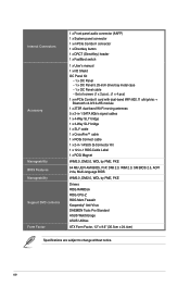
... signal cables 1 x 4-Way SLI® bridge 1 x 3-Way SLI® bridge 1 x SLI® cable 1 x CrossFire™ cable 1 x ROG Connect cable 1 x 2-in-1 ASUS Q-Connector Kit 1 x 12-in-1 ROG Cable Label 1 x ROG Magnet WfM2.0, DMI2.0, WOL by PME, PXE 64 Mb UEFI AMI BIOS, PnP, DMI 2.0, WfM 2.0, SM BIOS....0, DMI2.0, WOL by PME, PXE Drivers ROG RAMDisk ROG CPU-Z ROG Mem TweakIt Kaspersky® Anti-Virus DAEMON Tools Pro Standard ASUS WebStorage ASUS Utilities ATX Form Factor, 12" x 9.6" (30.5cm x 24.4cm) Specifications are subject to change without notice. Internal Connectors Accessory Manageability ...
... signal cables 1 x 4-Way SLI® bridge 1 x 3-Way SLI® bridge 1 x SLI® cable 1 x CrossFire™ cable 1 x ROG Connect cable 1 x 2-in-1 ASUS Q-Connector Kit 1 x 12-in-1 ROG Cable Label 1 x ROG Magnet WfM2.0, DMI2.0, WOL by PME, PXE 64 Mb UEFI AMI BIOS, PnP, DMI 2.0, WfM 2.0, SM BIOS....0, DMI2.0, WOL by PME, PXE Drivers ROG RAMDisk ROG CPU-Z ROG Mem TweakIt Kaspersky® Anti-Virus DAEMON Tools Pro Standard ASUS WebStorage ASUS Utilities ATX Form Factor, 12" x 9.6" (30.5cm x 24.4cm) Specifications are subject to change without notice. Internal Connectors Accessory Manageability ...
MAXIMUS VI EXTREME User's Manual
Page 24
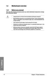
... it on a grounded antistatic pad or in the bag that came with the component. • Before you install or remove any component, ensure that the ATX power supply is switched off or the power cord is detached from the power supply. Chapter 1 1-6 Chapter 1: Product introduction
... it on a grounded antistatic pad or in the bag that came with the component. • Before you install or remove any component, ensure that the ATX power supply is switched off or the power cord is detached from the power supply. Chapter 1 1-6 Chapter 1: Product introduction
MAXIMUS VI EXTREME User's Manual
Page 61
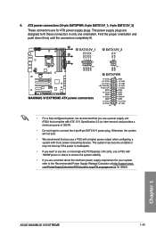
... fit. • For a fully configured system, we recommend that you use a power supply unit (PSU) that you use a PSU with ATX 12 V Specification 2.0 (or later version) and provides a minimum power of 350 W. • Do not forget to the Recommended Power Supply ...EATX12 V power plug. ATX power connectors (24-pin EATXPWR; 8-pin EATX12V_1; 4-pin EATX12V_2) These connectors are designed to use two or more high-end PCI Express x16 cards, use a PSU with a higher power output when configuring a system with more power-consuming devices. ASUS MAXIMUS VI EXTREME 1-43 Chapter 1 9....
... fit. • For a fully configured system, we recommend that you use a power supply unit (PSU) that you use a PSU with ATX 12 V Specification 2.0 (or later version) and provides a minimum power of 350 W. • Do not forget to the Recommended Power Supply ...EATX12 V power plug. ATX power connectors (24-pin EATXPWR; 8-pin EATX12V_1; 4-pin EATX12V_2) These connectors are designed to use two or more high-end PCI Express x16 cards, use a PSU with a higher power output when configuring a system with more power-consuming devices. ASUS MAXIMUS VI EXTREME 1-43 Chapter 1 9....
MAXIMUS VI EXTREME User's Manual
Page 62
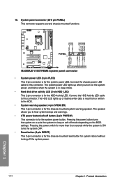
... the BIOS settings. The system power LED lights up or flashes when data is read from or written to hear system beeps and warnings. • ATX power button/soft-off button (2-pin PWRSW) This connector is for the HDD Activity LED. 10. System panel connector (20-8 pin PANEL) This connector supports...
... the BIOS settings. The system power LED lights up or flashes when data is read from or written to hear system beeps and warnings. • ATX power button/soft-off button (2-pin PWRSW) This connector is for the HDD Activity LED. 10. System panel connector (20-8 pin PANEL) This connector supports...
MAXIMUS VI EXTREME User's Manual
Page 92
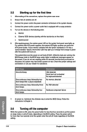
... you turned on the power, the system may light up or change from the time you press the ATX power button. While the tests are off the computer While the system is equipped with ATX power supplies, the system LED lights up . If you do not see anything within 30 seconds from...
... you turned on the power, the system may light up or change from the time you press the ATX power button. While the tests are off the computer While the system is equipped with ATX power supplies, the system LED lights up . If you do not see anything within 30 seconds from...

