
MAXIMUS V EXTREME User's Manual
Page 10
... slots are in use. *** The mini-PCIe slot is running at 4x speed. resolution of 2560 x 1600 @60Hz Supports HDMI with max. Intel® HD Graphics support Multi-VGA output support: Thunderbolt/DisplayPort/HDMI port Supports Thunderbolt with max. MAXIMUS V EXTREME specifications summary CPU Chipset Memory Expansion slots ...Turbo Boost Technology 2.0 * The Intel® Turbo Boost Technology 2.0 support depends on the CPU types. ** Refer to www.asus.com for details. 5 x PCI Express 3.0*/2.0 x16 slots [red] (single at native x16, or dual at x8/x8** mode, triple at x8/x16/x8, quad at x8/...
... slots are in use. *** The mini-PCIe slot is running at 4x speed. resolution of 2560 x 1600 @60Hz Supports HDMI with max. Intel® HD Graphics support Multi-VGA output support: Thunderbolt/DisplayPort/HDMI port Supports Thunderbolt with max. MAXIMUS V EXTREME specifications summary CPU Chipset Memory Expansion slots ...Turbo Boost Technology 2.0 * The Intel® Turbo Boost Technology 2.0 support depends on the CPU types. ** Refer to www.asus.com for details. 5 x PCI Express 3.0*/2.0 x16 slots [red] (single at native x16, or dual at x8/x8** mode, triple at x8/x16/x8, quad at x8/...

MAXIMUS V EXTREME User's Manual
Page 13
ASUS Q-Connector - ASUS Q-DIMM 1 x Thunderbolt port 1 x Clear CMOS button 1 x ROG Connect On/Off button 4 x USB 2.0 (1 port for ROG Connect) 1 xPS/2 keyboard/mouse combo port... 3 x Thermal sensor connectors 1 x 6-pin EZ Plug connector [black] (for PCIe slots) 1 x 4-pin EZ Plug connector [white] (for back I /O Ports Internal Connectors ASUS Q-Design - ASUS Q-Code - ASUS Q-LED (CPU, DRAM, VGA, Boot Device LED) - ASUS Q-Slot - ASUS Q-Shield - MAXIMUS V EXTREME specifications summary Special Features Back I /O and PCIe slots) 1 x LN2 Mode header 1 x Slow mode switch 1 x START (Power-on...
ASUS Q-Connector - ASUS Q-DIMM 1 x Thunderbolt port 1 x Clear CMOS button 1 x ROG Connect On/Off button 4 x USB 2.0 (1 port for ROG Connect) 1 xPS/2 keyboard/mouse combo port... 3 x Thermal sensor connectors 1 x 6-pin EZ Plug connector [black] (for PCIe slots) 1 x 4-pin EZ Plug connector [white] (for back I /O Ports Internal Connectors ASUS Q-Design - ASUS Q-Code - ASUS Q-LED (CPU, DRAM, VGA, Boot Device LED) - ASUS Q-Slot - ASUS Q-Shield - MAXIMUS V EXTREME specifications summary Special Features Back I /O and PCIe slots) 1 x LN2 Mode header 1 x Slow mode switch 1 x START (Power-on...

MAXIMUS V EXTREME User's Manual
Page 17
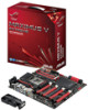
In the Republic of the best. It provides great graphics and system performance with its GPU, dual-channel DDR3 memory slots, and PCI Express 2.0/3.0 expansion slots. LGA1155 socket for Intel® 2nd/3rd Generation Core™ i7 / Core™ i5 / Core™ i3, Pentium... to optimize the PCIe allocation of Gamers and make your presence felt. If your character matches our trait, then join the elite Republic of multiple GPUs, it supports up to support multi-GPU SLI/ CrossFireX graphics cards for an unrivaled gaming performance. Chapter 1 ASUS MAXIMUS V EXTREME 1-1
In the Republic of the best. It provides great graphics and system performance with its GPU, dual-channel DDR3 memory slots, and PCI Express 2.0/3.0 expansion slots. LGA1155 socket for Intel® 2nd/3rd Generation Core™ i7 / Core™ i5 / Core™ i3, Pentium... to optimize the PCIe allocation of Gamers and make your presence felt. If your character matches our trait, then join the elite Republic of multiple GPUs, it supports up to support multi-GPU SLI/ CrossFireX graphics cards for an unrivaled gaming performance. Chapter 1 ASUS MAXIMUS V EXTREME 1-1

MAXIMUS V EXTREME User's Manual
Page 24
...black]) 16. BIOS Switch button 20. USB 2.0 connectors (10-1 pin USB56; EZ Plug connectors (6-pin EZ_PLUG_1; 1-4 EZ_PLUG_2) 25. DDR3 DIMM slots 5. VGA Hotwire connectors 7. Asmedia® Serial ATA 6.0 Gb/s connectors (7-pin SATA6G_E12/E34 [red]) 18. System panel connector (20-8 pin ...1-44 1-47 1-50 1-52 1-31 2-12 Chapter 1 1-8 Chapter 1: Product introduction Layout contents Connectors/Jumpers/Buttons and switches/Slots 1. LN2 Mode header 9. PCIe x16 Lane switch 12. RESET button 6. Q_Code LEDs 8. START (Power-on) button 11. Thermal sensor cable connectors (2-pin ...
...black]) 16. BIOS Switch button 20. USB 2.0 connectors (10-1 pin USB56; EZ Plug connectors (6-pin EZ_PLUG_1; 1-4 EZ_PLUG_2) 25. DDR3 DIMM slots 5. VGA Hotwire connectors 7. Asmedia® Serial ATA 6.0 Gb/s connectors (7-pin SATA6G_E12/E34 [red]) 18. System panel connector (20-8 pin ...1-44 1-47 1-50 1-52 1-31 2-12 Chapter 1 1-8 Chapter 1: Product introduction Layout contents Connectors/Jumpers/Buttons and switches/Slots 1. LN2 Mode header 9. PCIe x16 Lane switch 12. RESET button 6. Q_Code LEDs 8. START (Power-on) button 11. Thermal sensor cable connectors (2-pin ...

MAXIMUS V EXTREME User's Manual
Page 41
Failure to do so may cause you physical injury and damage motherboard components. Chapter 1 Slot No. 1 2 3 4 5 5 Slot Description PCIe 3.0/2.0 x16/x8_1 slot PCIe 3.0/2.0 x16_2A slot PCIe 3.0/2.0 x8_2B slot PCIe 3.0/2.0 x8_3 slot PCIe 2.0/1.1 x4_1 slot PCIe 3.0/2.0 x8_4 slot ASUS MAXIMUS V EXTREME 1-25 1.2.5 Expansion slots Unplug the power cord before adding or removing expansion cards.
Failure to do so may cause you physical injury and damage motherboard components. Chapter 1 Slot No. 1 2 3 4 5 5 Slot Description PCIe 3.0/2.0 x16/x8_1 slot PCIe 3.0/2.0 x16_2A slot PCIe 3.0/2.0 x8_2B slot PCIe 3.0/2.0 x8_3 slot PCIe 2.0/1.1 x4_1 slot PCIe 3.0/2.0 x8_4 slot ASUS MAXIMUS V EXTREME 1-25 1.2.5 Expansion slots Unplug the power cord before adding or removing expansion cards.

MAXIMUS V EXTREME User's Manual
Page 42
... x8 (Native) x8 (Native) PCIe 3.0/2.0_x16_2A - - x16 x16 PCIe 3.0/2.0_x8_2B - PCIe 3.0/2.0_x8_4 - - x8 x8 - - Chapter 1 1-26 Chapter 1: Product introduction x8 (Native) - - PCIe 3.0/2.0_x8_3 - x8 • We...PCIe 3.0 speed rate. • When the system is running with four VGA cards, ensure to connect the EZ PLUG_1/2 for extra PCIe power supply. • PCIe 3.0/2.0_x16/x8_1 slot switches to x8 mode when other PCIe 3.0/2.0 slots are occupied. • PCIe 3.0/2.0_x8_2B slot will be disabled when PCIe 3.0/2.0_x16_2A, PCIe 3.0/2.0_ x8_3, PCIe 3.0/2.0_x8_4 slots...
... x8 (Native) x8 (Native) PCIe 3.0/2.0_x16_2A - - x16 x16 PCIe 3.0/2.0_x8_2B - PCIe 3.0/2.0_x8_4 - - x8 x8 - - Chapter 1 1-26 Chapter 1: Product introduction x8 (Native) - - PCIe 3.0/2.0_x8_3 - x8 • We...PCIe 3.0 speed rate. • When the system is running with four VGA cards, ensure to connect the EZ PLUG_1/2 for extra PCIe power supply. • PCIe 3.0/2.0_x16/x8_1 slot switches to x8 mode when other PCIe 3.0/2.0 slots are occupied. • PCIe 3.0/2.0_x8_2B slot will be disabled when PCIe 3.0/2.0_x16_2A, PCIe 3.0/2.0_ x8_3, PCIe 3.0/2.0_x8_4 slots...

MAXIMUS V EXTREME User's Manual
Page 46
... This DIP switch allows you can slide the switch to find out the faulty one of the installed PCIe x16 cards is out of order, you to enable and disable the corresponding PCIe x16 slots. Slow Mode switch Slow Mode switch allows your system to [Enable] before using the LN2 cooling system. When...
... This DIP switch allows you can slide the switch to find out the faulty one of the installed PCIe x16 cards is out of order, you to enable and disable the corresponding PCIe x16 slots. Slow Mode switch Slow Mode switch allows your system to [Enable] before using the LN2 cooling system. When...

MAXIMUS V EXTREME User's Manual
Page 111
... VCCIO Full Phase Control. Configuration options: [Disabled] [Enabled] VGA Tweakers' Paradise The sub-items in its allocated PCIe slots. The values range from 110 to adjust the value. Use the and keys to 131. The voltage setting is... no cards are inserted in this menu allows you to raise or reduce an auxiliary power supply support for PCIe slots. The values range from 1.200V to set the VGA settings. Use the and keys to adjust the value... the value. The values range from 2.900V to 1.600V with 0.100V interval. Chapter 3 ASUS MAXIMUS V EXTREME 3-15
... VCCIO Full Phase Control. Configuration options: [Disabled] [Enabled] VGA Tweakers' Paradise The sub-items in its allocated PCIe slots. The values range from 110 to adjust the value. Use the and keys to 131. The voltage setting is... no cards are inserted in this menu allows you to raise or reduce an auxiliary power supply support for PCIe slots. The values range from 1.200V to set the VGA settings. Use the and keys to adjust the value... the value. The values range from 2.900V to 1.600V with 0.100V interval. Chapter 3 ASUS MAXIMUS V EXTREME 3-15

