
MAXIMUS V EXTREME User's Manual
Page 3
... guide...viii MAXIMUS V EXTREME specifications summary x Package contents...xv Installation tools and components xvi Chapter 1: Product introduction 1-1 1.1 Special features 1-1 1.1.1 Product highlights 1-1 1.1.2 ROG Intelligent Performance & Overclocking features 1-2 1.1.3 ASUS special features 1-4 1.1.4 ROG-rich bundled software 1-4 1.2 Motherboard overview 1-6 1.2.1 Before you proceed 1-6 1.2.2 Motherboard layout 1-7 1.2.3 Central Processing Unit (CPU 1-9 1.2.4 System memory 1-10 1.2.5 Expansion slots 1-25 1.2.6 Onboard buttons and switches 1-28...
... guide...viii MAXIMUS V EXTREME specifications summary x Package contents...xv Installation tools and components xvi Chapter 1: Product introduction 1-1 1.1 Special features 1-1 1.1.1 Product highlights 1-1 1.1.2 ROG Intelligent Performance & Overclocking features 1-2 1.1.3 ASUS special features 1-4 1.1.4 ROG-rich bundled software 1-4 1.2 Motherboard overview 1-6 1.2.1 Before you proceed 1-6 1.2.2 Motherboard layout 1-7 1.2.3 Central Processing Unit (CPU 1-9 1.2.4 System memory 1-10 1.2.5 Expansion slots 1-25 1.2.6 Onboard buttons and switches 1-28...

MAXIMUS V EXTREME User's Manual
Page 24
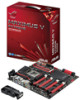
Layout contents Connectors/Jumpers/Buttons and switches/Slots 1. RESET button 6. Intel® Z77 Serial ATA 3.0 Gb/s connectors (7-pin SATA3G_1/2 [black]) 16. USB78) 22. Front panel audio connector (10-1 pin AAFP) 24....chassis, and optional fan connectors (4-pin CPU_FAN, 4-pin CPU_OPT, 4-pin OPT_FAN1-3, 4-pin CHA_FAN1-3) 4. LN2 Mode header 9. Slow Mode switch 10. PCIe x16 Lane switch 12. Asmedia® Serial ATA 6.0 Gb/s connectors (7-pin SATA6G_E12/E34 [red]) 18. Subzero Sense connector 19. BIOS Switch button 20. Digital audio connector (4-1 pin SPDIF_OUT) 23. ROG Connect...
Layout contents Connectors/Jumpers/Buttons and switches/Slots 1. RESET button 6. Intel® Z77 Serial ATA 3.0 Gb/s connectors (7-pin SATA3G_1/2 [black]) 16. USB78) 22. Front panel audio connector (10-1 pin AAFP) 24....chassis, and optional fan connectors (4-pin CPU_FAN, 4-pin CPU_OPT, 4-pin OPT_FAN1-3, 4-pin CHA_FAN1-3) 4. LN2 Mode header 9. Slow Mode switch 10. PCIe x16 Lane switch 12. Asmedia® Serial ATA 6.0 Gb/s connectors (7-pin SATA6G_E12/E34 [red]) 18. Subzero Sense connector 19. BIOS Switch button 20. Digital audio connector (4-1 pin SPDIF_OUT) 23. ROG Connect...

MAXIMUS V EXTREME User's Manual
Page 45
Chapter 1 ASUS MAXIMUS V EXTREME 1-29 GO button Press the GO button before POST to switch BIOS and load different BIOS settings. Press the BIOS button to enable MemOK! BIOS Switch button The motherboard comes with two BIOS. or press it to quickly load the preset profile (GO_Button file) for temporary overclocking when in OS. 4. 3. The nearby BIOS LEDs indicate the BIOS you are using.
Chapter 1 ASUS MAXIMUS V EXTREME 1-29 GO button Press the GO button before POST to switch BIOS and load different BIOS settings. Press the BIOS button to enable MemOK! BIOS Switch button The motherboard comes with two BIOS. or press it to quickly load the preset profile (GO_Button file) for temporary overclocking when in OS. 4. 3. The nearby BIOS LEDs indicate the BIOS you are using.

MAXIMUS V EXTREME User's Manual
Page 50
BIOS LED The BIOS LEDs help indicate the BIOS activity. Press the BIOS button to the Q-Code table on the next page for details. Refer to switch between BIOS1 and BIOS2 and the LED lights up when the corresponding BIOS is in use. 6. Q-Code LEDs The Q-Code LED design provides you with a 2-digit error code that displays the system status. 5. Chapter 1 1-34 Chapter 1: Product introduction
BIOS LED The BIOS LEDs help indicate the BIOS activity. Press the BIOS button to the Q-Code table on the next page for details. Refer to switch between BIOS1 and BIOS2 and the LED lights up when the corresponding BIOS is in use. 6. Q-Code LEDs The Q-Code LED design provides you with a 2-digit error code that displays the system status. 5. Chapter 1 1-34 Chapter 1: Product introduction

MAXIMUS V EXTREME User's Manual
Page 65
... Activity LED cable to the HDD. • System warning speaker (4-pin SPEAKER) This 4-pin connector is for the chassis-mounted reset button for the system power LED. Pressing the power switch for more than four seconds while the system is ON turns the system OFF. • Reset...button/soft-off mode depending on or puts the system in sleep mode. • Hard disk drive activity LED (2-pin IDE_LED) This 2-pin connector is for the HDD Activity LED. The IDE LED lights up when you to this connector. Pressing the power button turns the system on the BIOS settings. ASUS MAXIMUS V EXTREME...
... Activity LED cable to the HDD. • System warning speaker (4-pin SPEAKER) This 4-pin connector is for the chassis-mounted reset button for the system power LED. Pressing the power switch for more than four seconds while the system is ON turns the system OFF. • Reset...button/soft-off mode depending on or puts the system in sleep mode. • Hard disk drive activity LED (2-pin IDE_LED) This 2-pin connector is for the HDD Activity LED. The IDE LED lights up when you to this connector. Pressing the power button turns the system on the BIOS settings. ASUS MAXIMUS V EXTREME...

MAXIMUS V EXTREME User's Manual
Page 96
... LED lights up when you turned on the power, the system may light up or change from the time you press the ATX power button. Press the power switch for less than four seconds to a power outlet that all the connections, replace the system case cover. 2. If your retailer for the... short beeps One continuous beep followed by four short beeps Description VGA detected Quick boot set to green after the system LED turns on the BIOS setting. 2.4 Starting up for assistance. Connect the power cord to put the system on sleep mode or soft-off . 3. Follow the instructions in ...
... LED lights up when you turned on the power, the system may light up or change from the time you press the ATX power button. Press the power switch for less than four seconds to a power outlet that all the connections, replace the system case cover. 2. If your retailer for the... short beeps One continuous beep followed by four short beeps Description VGA detected Quick boot set to green after the system LED turns on the BIOS setting. 2.4 Starting up for assistance. Connect the power cord to put the system on sleep mode or soft-off . 3. Follow the instructions in ...

MAXIMUS V EXTREME User's Manual
Page 98
... does not support the bluetooth devices. Entering BIOS Setup after POST To enter BIOS Setup after changing any BIOS setting, load the default settings to enter BIOS Setup using the first two options. • The BIOS setup screens shown in using the BIOS Setup program. See section 1.2.6 Onboard buttons and switches for details. • If the system fails...
... does not support the bluetooth devices. Entering BIOS Setup after POST To enter BIOS Setup after changing any BIOS setting, load the default settings to enter BIOS Setup using the first two options. • The BIOS setup screens shown in using the BIOS Setup program. See section 1.2.6 Onboard buttons and switches for details. • If the system fails...

MAXIMUS V EXTREME User's Manual
Page 116
See section 1.2.6 Onboard buttons and switches for information on how to erase the RTC RAM via the Clear CMOS button. • The Administrator or User Password items on top of the screen show [Installed]. 3-20 Chapter 3: BIOS setup Chapter 3 After you to set a password, these items show the default [Not Installed]. Security The Security ...the basic system information, and allows you set the system date, time, language, and security settings. The Main menu provides you an overview of the BIOS Setup program. 3.4 Main menu The Main menu screen appears when you have forgotten your...
See section 1.2.6 Onboard buttons and switches for information on how to erase the RTC RAM via the Clear CMOS button. • The Administrator or User Password items on top of the screen show [Installed]. 3-20 Chapter 3: BIOS setup Chapter 3 After you to set a password, these items show the default [Not Installed]. Security The Security ...the basic system information, and allows you set the system date, time, language, and security settings. The Main menu provides you an overview of the BIOS Setup program. 3.4 Main menu The Main menu screen appears when you have forgotten your...


