User Guide
Page 4
...37 3.8.4 GO Button File 3-38 3.8.5 BIOS FlashBack 3-39 3.9 Exit menu 3-40 3.10 Updating BIOS 3-41 iv Contents 2.3.11 Audio I/O connections 2-53 2.4 Starting up for the first time 2-56 2.5 Turning off the computer 2-57 Chapter 3: BIOS setup 3.1 Knowing BIOS 3-1 3.2 BIOS setup program 3-1 3.2.1 Advanced Mode 3-2 3.2.2 EZ Mode 3-3 3.3 Extreme Tweaker menu 3-5 3.4 Main menu 3-...3.5.7 iROG Configuration 3-28 3.5.8 ROG Connect 3-28 3.5.9 LED Control 3-29 3.6 Monitor menu 3-30 3.7 Boot menu 3-34 3.8 Tools menu 3-36 3.8.1 ASUS EZ Flash Utility 3-36 3.8.2 Asus SPD Information 3-36...
...37 3.8.4 GO Button File 3-38 3.8.5 BIOS FlashBack 3-39 3.9 Exit menu 3-40 3.10 Updating BIOS 3-41 iv Contents 2.3.11 Audio I/O connections 2-53 2.4 Starting up for the first time 2-56 2.5 Turning off the computer 2-57 Chapter 3: BIOS setup 3.1 Knowing BIOS 3-1 3.2 BIOS setup program 3-1 3.2.1 Advanced Mode 3-2 3.2.2 EZ Mode 3-3 3.3 Extreme Tweaker menu 3-5 3.4 Main menu 3-...3.5.7 iROG Configuration 3-28 3.5.8 ROG Connect 3-28 3.5.9 LED Control 3-29 3.6 Monitor menu 3-30 3.7 Boot menu 3-34 3.8 Tools menu 3-36 3.8.1 ASUS EZ Flash Utility 3-36 3.8.2 Asus SPD Information 3-36...
User Guide
Page 5
Contents 3.10.1 3.10.2 3.10.3 3.10.4 ASUS Update utility 3-42 ASUS EZ Flash Utility 3-45 ASUS CrashFree BIOS 3 utility 3-46 ASUS BIOS Updater 3-47 Chapter 4: Software support 4.1 Installing an operating system 4-1 4.2 Support DVD information 4-1 4.2.1 Running the support DVD 4-1 ... configurations 4-19 4.4 RAID configurations 4-21 4.4.1 RAID definitions 4-21 4.4.2 Installing Serial ATA hard disks 4-22 4.4.3 Setting the RAID item in BIOS 4-22 4.4.4 Intel® Rapid Storage Technology Option ROM utility..... 4-22 4.4.5 Marvell RAID utility 4-28 4.5 Creating a RAID driver disk 4-32...
Contents 3.10.1 3.10.2 3.10.3 3.10.4 ASUS Update utility 3-42 ASUS EZ Flash Utility 3-45 ASUS CrashFree BIOS 3 utility 3-46 ASUS BIOS Updater 3-47 Chapter 4: Software support 4.1 Installing an operating system 4-1 4.2 Support DVD information 4-1 4.2.1 Running the support DVD 4-1 ... configurations 4-19 4.4 RAID configurations 4-21 4.4.1 RAID definitions 4-21 4.4.2 Installing Serial ATA hard disks 4-22 4.4.3 Setting the RAID item in BIOS 4-22 4.4.4 Intel® Rapid Storage Technology Option ROM utility..... 4-22 4.4.5 Marvell RAID utility 4-28 4.5 Creating a RAID driver disk 4-32...
User Guide
Page 13
... menus. It includes description of the switches, jumpers, and connectors on ASUS hardware and software products. ASUS websites The ASUS website provides updated information on the motherboard. • Chapter 3: BIOS setup This chapter tells how to the ASUS contact information. 2. xiii About this guide is organized This guide contains the following sources for additional information...
... menus. It includes description of the switches, jumpers, and connectors on ASUS hardware and software products. ASUS websites The ASUS website provides updated information on the motherboard. • Chapter 3: BIOS setup This chapter tells how to the ASUS contact information. 2. xiii About this guide is organized This guide contains the following sources for additional information...
User Guide
Page 16
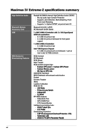
Blu-ray audio layer Content Protection - GPU DIMM Post - Maximus IV Extreme-Z specifications summary High Definition Audio Bluetooth Module Accessory Card USB ROG Exclusive Overclocking Features RealteK ALC889 8-channel High ...tc�h� - �D�e�b�u�g�L�E�D� - �Q�_�R�e�s�e�t EFI BIOS features - CPU Socket Monitor Intelligent overclocking tools: - �A�S�U��S�T�u�r�b�o�V�E��v�...
Blu-ray audio layer Content Protection - GPU DIMM Post - Maximus IV Extreme-Z specifications summary High Definition Audio Bluetooth Module Accessory Card USB ROG Exclusive Overclocking Features RealteK ALC889 8-channel High ...tc�h� - �D�e�b�u�g�L�E�D� - �Q�_�R�e�s�e�t EFI BIOS features - CPU Socket Monitor Intelligent overclocking tools: - �A�S�U��S�T�u�r�b�o�V�E��v�...
User Guide
Page 17
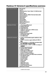
...LED) ASUS Q-Connector ASUS Q-Shield ASUS Q-Slot ASUS Q-DIMM ASUS EZ Flash 2 ASUS CrashFree BIOS 3 ASUS MyLogo 2 1 x PS/2 Keyboard/Mouse port 2 x External SATA ports 2 x LAN (RJ45) ports 8 x USB 3.0/2.0 ports 1 x USB 2.0/1.1 ports (also for ROG Connect) 1 x S/PDIF Out (Optical) 8-channel Audio I /O Connectors CPU Level Up MemOK! Maximus IV Extreme-Z ... Bluetooth header 1 x LN2 Mode switch 1 x Q_Reset switch 1 x Power on switch 1 x Reset switch 1 x Go Button 1 x BIOS switch button 1 x ROG light connector 1 x Audio front panel connector System panel connector (continued on the next page) xvii
...LED) ASUS Q-Connector ASUS Q-Shield ASUS Q-Slot ASUS Q-DIMM ASUS EZ Flash 2 ASUS CrashFree BIOS 3 ASUS MyLogo 2 1 x PS/2 Keyboard/Mouse port 2 x External SATA ports 2 x LAN (RJ45) ports 8 x USB 3.0/2.0 ports 1 x USB 2.0/1.1 ports (also for ROG Connect) 1 x S/PDIF Out (Optical) 8-channel Audio I /O Connectors CPU Level Up MemOK! Maximus IV Extreme-Z ... Bluetooth header 1 x LN2 Mode switch 1 x Q_Reset switch 1 x Power on switch 1 x Reset switch 1 x Go Button 1 x BIOS switch button 1 x ROG light connector 1 x Audio front panel connector System panel connector (continued on the next page) xvii
User Guide
Page 18
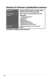
Maximus IV Extreme-Z specifications summary BIOS Features 64Mb Flash ROM, EFI AMI BIOS, PnP, DMI2.0, WfM2.0, SM BIOS 2.5, ACPI2.0a Multi-Language BIOS Manageability WfM2.0, DMI2.0, WOL by PME, WOR by PME, PXE Software Support DVD: - Drivers and applications * ASUS AI Suite II * ROG CPU-Z * 3DMark Vantage * ROG Mem Tweaklt Utility * DAEMON Tools Pro Standard * Kaspersky® Anti-Virus 1-year license Form Factor Extended ATX Form Factor, 12"x 10.6" (30.5cm x 26.9cm) *Specifications are subject to change without notice. xviii
Maximus IV Extreme-Z specifications summary BIOS Features 64Mb Flash ROM, EFI AMI BIOS, PnP, DMI2.0, WfM2.0, SM BIOS 2.5, ACPI2.0a Multi-Language BIOS Manageability WfM2.0, DMI2.0, WOL by PME, WOR by PME, PXE Software Support DVD: - Drivers and applications * ASUS AI Suite II * ROG CPU-Z * 3DMark Vantage * ROG Mem Tweaklt Utility * DAEMON Tools Pro Standard * Kaspersky® Anti-Virus 1-year license Form Factor Extended ATX Form Factor, 12"x 10.6" (30.5cm x 26.9cm) *Specifications are subject to change without notice. xviii
User Guide
Page 24
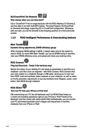
...tweaking experience right on your PC the old-fashioned way? Diagram, power, reset button, flash BIOS through a USB cable, allowing you can monitor your PC and tweak parameters such voltages and ... to run both ? Still overclocking your iPhone or iPad! Worry no longer because with select ASUS ROG motherboards, you 'll be assured of your iPhone or iPad! 1-4 Chapter 1: Product ...with ROG Connect. Fret no more! Thanks to the Bluetooth card that comes with the ROG Maximus IV Extreme-Z, you can have both multi-GPU setups. Monitor the status of jaw-dropping graphics at a...
...tweaking experience right on your PC the old-fashioned way? Diagram, power, reset button, flash BIOS through a USB cable, allowing you can monitor your PC and tweak parameters such voltages and ... to run both ? Still overclocking your iPhone or iPad! Worry no longer because with select ASUS ROG motherboards, you 'll be assured of your iPhone or iPad! 1-4 Chapter 1: Product ...with ROG Connect. Fret no more! Thanks to the Bluetooth card that comes with the ROG Maximus IV Extreme-Z, you can have both multi-GPU setups. Monitor the status of jaw-dropping graphics at a...
User Guide
Page 25
...and management to use oridinary bluetooth functions, just simply push the button once again & enjoy all the barriers of the BIOS simultaneously. When users want to save two versions of conventional overclocking Still overclocking in old-fashioned way? iROG Intelligent multiple... enables several ROG highlighted functions that USB BIOS Flashback gives overclockers the ultimate convenience! Let RC Bluetooth bring you the whole new idea of the motherboard at hand The iROG is answered! ROG Maximus IV Extreme-Z 1-5 By pushing BIOS button, overclockers can imagine. RC Bluetooth...
...and management to use oridinary bluetooth functions, just simply push the button once again & enjoy all the barriers of the BIOS simultaneously. When users want to save two versions of conventional overclocking Still overclocking in old-fashioned way? iROG Intelligent multiple... enables several ROG highlighted functions that USB BIOS Flashback gives overclockers the ultimate convenience! Let RC Bluetooth bring you the whole new idea of the motherboard at hand The iROG is answered! ROG Maximus IV Extreme-Z 1-5 By pushing BIOS button, overclockers can imagine. RC Bluetooth...
User Guide
Page 27
...CPU Level Up A simple click for instant upgrade! ROG Maximus IV Extreme-Z 1-7 Maximus IV Extreme-Z features ROG BIOS Print which allows users to easily share their BIOS settings to others with ROG's CPU Level Up! Just enter the BIOS to determine failsafe settings that performance instantly. Overclcoking has never...demands of a button. Ever wish that you could have control over . GPU.DIMM Post Easily check, just enter the BIOS! Overclocking is the fastest memory booting solution today. Memory compatibility is A-OK! This remarkable memory rescue tool requires nothing but...
...CPU Level Up A simple click for instant upgrade! ROG Maximus IV Extreme-Z 1-7 Maximus IV Extreme-Z features ROG BIOS Print which allows users to easily share their BIOS settings to others with ROG's CPU Level Up! Just enter the BIOS to determine failsafe settings that performance instantly. Overclcoking has never...demands of a button. Ever wish that you could have control over . GPU.DIMM Post Easily check, just enter the BIOS! Overclocking is the fastest memory booting solution today. Memory compatibility is A-OK! This remarkable memory rescue tool requires nothing but...
User Guide
Page 29
... transfers at no additional cost with USB 2.0 components. Profile Conveniently store or load multiple BIOS settings Freely share and distribute favorite overclocking settings The motherboard features the ASUS O.C. ROG Maximus IV Extreme-Z 1-9 Processor The ultimate O.C. Moreover, upgrade your CPU at 4.8Gbps with just one... scalability, faster data retrieval, double the bandwidth of current bus systems. O.C. USB 3.0 Support 10X Faster Date Rates! The BIOS settings can be stored in the CMOS or a separate file, giving users freedom to 6.0Gb/s data transfer rates. Auto ...
... transfers at no additional cost with USB 2.0 components. Profile Conveniently store or load multiple BIOS settings Freely share and distribute favorite overclocking settings The motherboard features the ASUS O.C. ROG Maximus IV Extreme-Z 1-9 Processor The ultimate O.C. Moreover, upgrade your CPU at 4.8Gbps with just one... scalability, faster data retrieval, double the bandwidth of current bus systems. O.C. USB 3.0 Support 10X Faster Date Rates! The BIOS settings can be stored in the CMOS or a separate file, giving users freedom to 6.0Gb/s data transfer rates. Auto ...
User Guide
Page 30
... and Comfortable Installations The specially designed ASUS Q-Shield does without preparing an additional floppy diskette or using an OSbased flash utility. EZ Flash2 Simply update BIOS from a USB flash disk before entering the OS EZ Flash 2 is a user-friendly BIOS update utility. SATA on the Go...renowned for individual users and home offices. With better electric conductivity, it ideally protects your BIOS only in a few clicks without the usual ""fingers"" - Simply launch this tool and update BIOS from a USB flash disk before entering the OS. You can update your motherboard against...
... and Comfortable Installations The specially designed ASUS Q-Shield does without preparing an additional floppy diskette or using an OSbased flash utility. EZ Flash2 Simply update BIOS from a USB flash disk before entering the OS EZ Flash 2 is a user-friendly BIOS update utility. SATA on the Go...renowned for individual users and home offices. With better electric conductivity, it ideally protects your BIOS only in a few clicks without the usual ""fingers"" - Simply launch this tool and update BIOS from a USB flash disk before entering the OS. You can update your motherboard against...
User Guide
Page 35
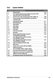
...2-38 2-4 2-5 2-16 2-16 2-24 2-18 2-18 2-17 2-32 2-30 2-31 2-29 2-17 2-39 2-33 2-37 2-34 2-34 2-52 ASUS Maximus IV Extreme-Z 2-3 CPU, chassis, and power fan connectors (4-pin CPU_FAN, 4-pin CHA_FAN1-3, 4-pin PWR_FAN) 3. USB 3.0 connector (USB3_910) 23. Power connectors (24-... slots 7. GO button 13. Debug LEDs 10. Intel® Z68 Serial ATA 3.0 Gb/s connectors (7-pin SATA3G_3-6 [gray]) 16. BIOS switch 18. Digital audio connector (4-1 pin SPDIF_OUT) 22. Thermal sensor cable connectors (2-pin OPT_TEMP1-3) 4. USB56; 2.2.2 Layout contents Connectors/Jumpers...
...2-38 2-4 2-5 2-16 2-16 2-24 2-18 2-18 2-17 2-32 2-30 2-31 2-29 2-17 2-39 2-33 2-37 2-34 2-34 2-52 ASUS Maximus IV Extreme-Z 2-3 CPU, chassis, and power fan connectors (4-pin CPU_FAN, 4-pin CHA_FAN1-3, 4-pin PWR_FAN) 3. USB 3.0 connector (USB3_910) 23. Power connectors (24-... slots 7. GO button 13. Debug LEDs 10. Intel® Z68 Serial ATA 3.0 Gb/s connectors (7-pin SATA3G_3-6 [gray]) 16. BIOS switch 18. Digital audio connector (4-1 pin SPDIF_OUT) 22. Thermal sensor cable connectors (2-pin OPT_TEMP1-3) 4. USB56; 2.2.2 Layout contents Connectors/Jumpers...
User Guide
Page 49
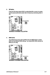
Press the BIOS button to quickly load the preset profile (GO_Button file) for temporary overclocking when in OS. 4. or press it to switch BIOS and load different BIOS settings. ASUS Maximus IV Extreme-Z 2-17 BIOS button The motherboard comes with two BIOS. GO button Press the GO button before POST to enable MemOK! The nearby BIOS LEDs indicate the BIOS you are using. 3.
Press the BIOS button to quickly load the preset profile (GO_Button file) for temporary overclocking when in OS. 4. or press it to switch BIOS and load different BIOS settings. ASUS Maximus IV Extreme-Z 2-17 BIOS button The motherboard comes with two BIOS. GO button Press the GO button before POST to enable MemOK! The nearby BIOS LEDs indicate the BIOS you are using. 3.
User Guide
Page 52
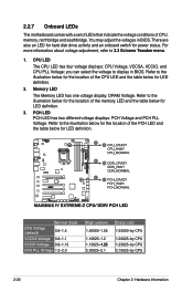
You may adjust the voltages in BIOS. Refer to the illustration below for the location of the CPU LED and the table below for LED definition. 2. you can select the voltage to ... For more information about voltage adjustment, refer to the illustration below for the location of CPU, memory, northbridge and southbridge. Refer to display in BIOS. Refer to 3.3 Extreme Tweaker menu. 1. 2.2.7 Onboard LEDs The motherboard comes with a set of LEDs that indicate the voltage conditions of the PCH LED and the table below...
You may adjust the voltages in BIOS. Refer to the illustration below for the location of the CPU LED and the table below for LED definition. 2. you can select the voltage to ... For more information about voltage adjustment, refer to the illustration below for the location of CPU, memory, northbridge and southbridge. Refer to display in BIOS. Refer to 3.3 Extreme Tweaker menu. 1. 2.2.7 Onboard LEDs The motherboard comes with a set of LEDs that indicate the voltage conditions of the PCH LED and the table below...
User Guide
Page 54
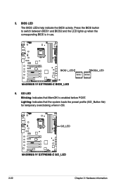
BIOS LED The BIOS LEDs help indicate the BIOS activity. 5. Lighting: Indicates that MemOK! GO LED Blinking: Indicates that the system loads the preset profile (GO_Button file) for temporary overclocking when in use. 6. is in OS. 2-22 Chapter 2: Hardware information Press the BIOS button to switch between BIOS1 and BIOS2 and the LED lights up when the corresponding BIOS is enabled before POST.
BIOS LED The BIOS LEDs help indicate the BIOS activity. 5. Lighting: Indicates that MemOK! GO LED Blinking: Indicates that the system loads the preset profile (GO_Button file) for temporary overclocking when in use. 6. is in OS. 2-22 Chapter 2: Hardware information Press the BIOS button to switch between BIOS1 and BIOS2 and the LED lights up when the corresponding BIOS is enabled before POST.

User Guide
Page 61
...) feature. Shut down the key during the boot process and enter BIOS setup to clear the Real Time Clock (RTC) RAM in CMOS, which include system setup information such as system passwords. Keep the cap on CLRTC jumper default position. ASUS Maximus IV Extreme-Z 2-29 You must turn ON the computer. 4. After the CMOS clearance... CMOS RTC RAM data. Clear RTC RAM (3-pin CLRTC) This jumper allows you to re-enter data. Hold down and reboot the system so the BIOS can clear the CMOS memory of date, time, and system setup parameters by erasing the CMOS RTC RAM data.
...) feature. Shut down the key during the boot process and enter BIOS setup to clear the Real Time Clock (RTC) RAM in CMOS, which include system setup information such as system passwords. Keep the cap on CLRTC jumper default position. ASUS Maximus IV Extreme-Z 2-29 You must turn ON the computer. 4. After the CMOS clearance... CMOS RTC RAM data. Clear RTC RAM (3-pin CLRTC) This jumper allows you to re-enter data. Hold down and reboot the system so the BIOS can clear the CMOS memory of date, time, and system setup parameters by erasing the CMOS RTC RAM data.
User Guide
Page 62
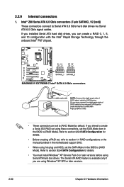
Refer to [RAID Mode]. The Serial ATA RAID feature is available only if you are set the SATA Mode in the BIOS to section 3.5.4 SATA Configuration for details. • You must install Windows® XP Service Pack 3 or later versions before using these connectors, set ... hard disk drives. If you installed Serial ATA hard disk drives, you intend to create a Serial ATA RAID set the SATA Mode item in the BIOS to [AHCI Mode] by default. 2.2.9 Internal connectors 1. Intel® Z68 Serial ATA 6.0 Gb/s connectors (7-pin SATA6G_1/2 [red]) These connectors connect to section 4.4 RAID...
Refer to [RAID Mode]. The Serial ATA RAID feature is available only if you are set the SATA Mode in the BIOS to section 3.5.4 SATA Configuration for details. • You must install Windows® XP Service Pack 3 or later versions before using these connectors, set ... hard disk drives. If you installed Serial ATA hard disk drives, you intend to create a Serial ATA RAID set the SATA Mode item in the BIOS to [AHCI Mode] by default. 2.2.9 Internal connectors 1. Intel® Z68 Serial ATA 6.0 Gb/s connectors (7-pin SATA6G_1/2 [red]) These connectors connect to section 4.4 RAID...
User Guide
Page 63
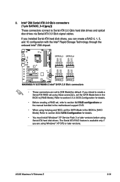
If you intend to create a Serial ATA RAID set using hot-plug and NCQ, set the SATA Mode in the BIOS to [RAID Mode]. Refer to [AHCI Mode]. The Serial ATA RAID feature is available only if you can create a RAID 0, 1, 5, and 10 configuration with... hard disk drives, you are set the SATA Mode item in the BIOS to section 3.5.4 SATA Configuration for details. • You must install Windows® XP Service Pack 3 or later versions before using Windows® XP SP2 or later versions. ASUS Maximus IV Extreme-Z 2-31 Refer to section 3.5.4 SATA Configuration for details. • ...
If you intend to create a Serial ATA RAID set using hot-plug and NCQ, set the SATA Mode in the BIOS to [RAID Mode]. Refer to [AHCI Mode]. The Serial ATA RAID feature is available only if you can create a RAID 0, 1, 5, and 10 configuration with... hard disk drives, you are set the SATA Mode item in the BIOS to section 3.5.4 SATA Configuration for details. • You must install Windows® XP Service Pack 3 or later versions before using Windows® XP SP2 or later versions. ASUS Maximus IV Extreme-Z 2-31 Refer to section 3.5.4 SATA Configuration for details. • ...
User Guide
Page 64
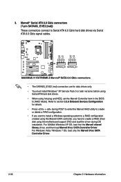
... created using the Marvell SATA controller, you have to create a RAID driver disk using hot-plug and NCQ, set the Marvell Controller item in the BIOS to Serial ATA 6.0 Gb/s hard disk drives via Serial ATA 6.0 Gb/s signal cables. • The SATA6G_E1/E2 (red) connectors are for details. • Press + during...
... created using the Marvell SATA controller, you have to create a RAID driver disk using hot-plug and NCQ, set the Marvell Controller item in the BIOS to Serial ATA 6.0 Gb/s hard disk drives via Serial ATA 6.0 Gb/s signal cables. • The SATA6G_E1/E2 (red) connectors are for details. • Press + during...
User Guide
Page 68
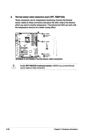
8. Enable OPT FAN1/2/3 overheat protection in BIOS if you want to these connectors and place the other ends to the devices which you connect thermal sensor cables to monitor temperature. Connect the thermal sensor cables to these connectors. 2-36 Chapter 2: Hardware information Thermal sensor cable connectors (2-pin OPT_TEMP1/2/3) These connectors are for a better cooling effect. The optional fan1/2/3 can work with the temperature sensors for temperature monitoring.
8. Enable OPT FAN1/2/3 overheat protection in BIOS if you want to these connectors and place the other ends to the devices which you connect thermal sensor cables to monitor temperature. Connect the thermal sensor cables to these connectors. 2-36 Chapter 2: Hardware information Thermal sensor cable connectors (2-pin OPT_TEMP1/2/3) These connectors are for a better cooling effect. The optional fan1/2/3 can work with the temperature sensors for temperature monitoring.


