
User Manual
Page 4
Contents 2.3.4 Storage Configuration 2-6 2.3.5 System Information 2-6 2.4 Advanced menu 2-6 2.4.1 JumperFree Configuration 2-7 2.4.2 CPU Configuration 2-9 2.4.3 Chipset 2-10 2.4.4 Onboard Devices Configuration 2-11 2.4.5 PCI PnP 2-11 2.4.6 USB Configuration 2-12 2.5 Power menu 2-12 2.5.1 Suspend Mode 2-13 2.5.2 ACPI 2.0 Support 2-13 2.5.3 ACPI APIC Support 2-13 2.5.4 APM Configuration 2-13 2.5.5 Hardware Monitor 2-14 2.6 Boot menu 2-14 2.6.1 Boot Device Priority 2-14 2.6.2 ...
Contents 2.3.4 Storage Configuration 2-6 2.3.5 System Information 2-6 2.4 Advanced menu 2-6 2.4.1 JumperFree Configuration 2-7 2.4.2 CPU Configuration 2-9 2.4.3 Chipset 2-10 2.4.4 Onboard Devices Configuration 2-11 2.4.5 PCI PnP 2-11 2.4.6 USB Configuration 2-12 2.5 Power menu 2-12 2.5.1 Suspend Mode 2-13 2.5.2 ACPI 2.0 Support 2-13 2.5.3 ACPI APIC Support 2-13 2.5.4 APM Configuration 2-13 2.5.5 Hardware Monitor 2-14 2.6 Boot menu 2-14 2.6.1 Boot Device Priority 2-14 2.6.2 ...

User Manual
Page 6
... product, contact a qualified service technician or your area. Safety information Electrical safety • To prevent electric shock hazard, disconnect the power cable from the electric outlet before relocating the system. • When adding or removing devices to change system settings through the BIOS ...setup menus. If possible, disconnect all cables are correctly connected and the power cables are not sure about the voltage of the motherboard and the new technology it by yourself. Operation safety • Before ...
... product, contact a qualified service technician or your area. Safety information Electrical safety • To prevent electric shock hazard, disconnect the power cable from the electric outlet before relocating the system. • When adding or removing devices to change system settings through the BIOS ...setup menus. If possible, disconnect all cables are correctly connected and the power cables are not sure about the voltage of the motherboard and the new technology it by yourself. Operation safety • Before ...

User Manual
Page 9
...M4N78-AM V2 specifications summary USB LAN ASUS special features ASUS overclocking features Back panel I/O ports Internal I /O shield 1 x User Manual MicroATX form factor: 9.6 in x 8.0 in (24.4 cm x 20.3 cm) Drivers ASUS Update ASUS PC Probe II Anti-Virus software (OEM version) *Specifications are subject to 10 USB 2.0/1.1 ports (6 ports at mid-board, 4 ports at 1MHz increment ASUS... 1 x S/PDIF_OUT connector 1 x 24-pin EATX power connector 1 x 4-pin ATX 12V power connector 8Mb Flash ROM, AMI BIOS, PnP, DMI v2.0, WfM2.0, ACPI v2.0a, SM BIOS v2.5 2 x Serial ATA cables 1 x Ultra DMA ...
...M4N78-AM V2 specifications summary USB LAN ASUS special features ASUS overclocking features Back panel I/O ports Internal I /O shield 1 x User Manual MicroATX form factor: 9.6 in x 8.0 in (24.4 cm x 20.3 cm) Drivers ASUS Update ASUS PC Probe II Anti-Virus software (OEM version) *Specifications are subject to 10 USB 2.0/1.1 ports (6 ports at mid-board, 4 ports at 1MHz increment ASUS... 1 x S/PDIF_OUT connector 1 x 24-pin EATX power connector 1 x 4-pin ATX 12V power connector 8Mb Flash ROM, AMI BIOS, PnP, DMI v2.0, WfM2.0, ACPI v2.0a, SM BIOS v2.5 2 x Serial ATA cables 1 x Ultra DMA ...
User Manual
Page 10
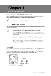
... the onboard LED. Before you uninstall any motherboard component. Onboard LED This motherboard comes with a standby power LED that lights up to page ix for buying an ASUS® M4N78-AM V2 motherboard! Chapter 1 Product introduction Thank you install or remove any of the items is damaged or missing... on a grounded antistatic pad or in any component, place it on it, check the items in soft-off the ATX power supply and detach its power cord. Standby Power 1-1 Chapter 1: Product introduction This is ON, in sleep mode, or in your retailer. 1.1 Before you proceed Take note...
... the onboard LED. Before you uninstall any motherboard component. Onboard LED This motherboard comes with a standby power LED that lights up to page ix for buying an ASUS® M4N78-AM V2 motherboard! Chapter 1 Product introduction Thank you install or remove any of the items is damaged or missing... on a grounded antistatic pad or in any component, place it on it, check the items in soft-off the ATX power supply and detach its power cord. Standby Power 1-1 Chapter 1: Product introduction This is ON, in sleep mode, or in your retailer. 1.1 Before you proceed Take note...

User Manual
Page 11
...Clear RTC RAM (3-pin CLRTC) Page 1-7 1-13 1-3 1-12 1-3 1-11 1-9 1-7 Connectors/Jumpers/Slots/LED 9. Keyboard power (3-pin KBPWR) Page 1-10 1-12 1-1 1-13 1-11 1-10 1-14 1-8 ASUS M4N78-AM V2 1-2 CPU fan connector (4-pin CPU_FAN) 5. COM1 SOCKET AM2+ Place this side towards the rear of the chassis. Doing so...chassis in connector (4-pin CD) 14. AM2+ CPU Socket 4. DDR2 DIMM slots 6. Internal speaker connector (4-pin SPEAKER) 8. Standby power LED (SB_PWR) 12. System panel connector (10-1 pin F_PANEL) 13. Optical drive audio in the correct orientation. Digital audio connector (4-1 pin ...
...Clear RTC RAM (3-pin CLRTC) Page 1-7 1-13 1-3 1-12 1-3 1-11 1-9 1-7 Connectors/Jumpers/Slots/LED 9. Keyboard power (3-pin KBPWR) Page 1-10 1-12 1-1 1-13 1-11 1-10 1-14 1-8 ASUS M4N78-AM V2 1-2 CPU fan connector (4-pin CPU_FAN) 5. COM1 SOCKET AM2+ Place this side towards the rear of the chassis. Doing so...chassis in connector (4-pin CD) 14. AM2+ CPU Socket 4. DDR2 DIMM slots 6. Internal speaker connector (4-pin SPEAKER) 8. Standby power LED (SB_PWR) 12. System panel connector (10-1 pin F_PANEL) 13. Optical drive audio in the correct orientation. Digital audio connector (4-1 pin ...
User Manual
Page 15
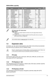
... No. Failure to do so may cause you may need to install expansion cards. Visit the ASUS website at www.asus.com for installation details. Refer to unplug the power cord before adding or removing expansion cards. DDR2-667MHz capability Vendor Part No. Ensure to the...injury and damage motherboard components. 1.5.1 PCI slots The PCI slots support cards such as one pair of dual-channel memory configuration. ASUS M4N78-AM V2 1-6 CL Chip Brand ADATA ADATA Apacer Apacer Corsair G.SKILL G.SKILL GEIL GEIL HY Kingmax M2OAD5G314170Q1C58 1G DS M2OAD5H3J4170I1C53 2G DS 78...
... No. Failure to do so may cause you may need to install expansion cards. Visit the ASUS website at www.asus.com for installation details. Refer to unplug the power cord before adding or removing expansion cards. DDR2-667MHz capability Vendor Part No. Ensure to the...injury and damage motherboard components. 1.5.1 PCI slots The PCI slots support cards such as one pair of dual-channel memory configuration. ASUS M4N78-AM V2 1-6 CL Chip Brand ADATA ADATA Apacer Apacer Corsair G.SKILL G.SKILL GEIL GEIL HY Kingmax M2OAD5G314170Q1C58 1G DS M2OAD5H3J4170I1C53 2G DS 78...

User Manual
Page 16
...RAM data. For system failure due to overclocking. Move the jumper cap from S1 sleep mode (CPU stopped, DRAM refreshed, system running in reduced power mode). 1-7 Chapter 1: Product introduction Shut down the key during the boot process and enter BIOS setup to default values. 2. Hold down and ... setup information such as system passwords. Clear RTC RAM (3-pin CLRTC) This jumper allows you to pins 1-2. 3. The onboard button cell battery powers the RAM data in CMOS. USB device wake-up (3-pin USBPW1-4, USBPW5-10) Set these jumpers to +5VSB to wake up the computer from...
...RAM data. For system failure due to overclocking. Move the jumper cap from S1 sleep mode (CPU stopped, DRAM refreshed, system running in reduced power mode). 1-7 Chapter 1: Product introduction Shut down the key during the boot process and enter BIOS setup to default values. 2. Hold down and ... setup information such as system passwords. Clear RTC RAM (3-pin CLRTC) This jumper allows you to pins 1-2. 3. The onboard button cell battery powers the RAM data in CMOS. USB device wake-up (3-pin USBPW1-4, USBPW5-10) Set these jumpers to +5VSB to wake up the computer from...
User Manual
Page 17
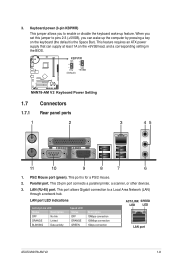
...corresponding setting in the BIOS. 1.7 1.7.1 1 Connectors Rear panel ports 2 3 45 11 10 9 8 7 6 1. Parallel port. This feature requires an ATX power supply that can wake up feature. This 25-pin port connects a parallel printer, a scanner, or other devices. 3. PS/2 Mouse port (green). This port is... Status OFF ORANGE GREEN Description 10Mbps connection 100Mbps connection 1Gbps connection ACT/LINK SPEED LED LED LAN port ASUS M4N78-AM V2 1-8 Keyboard power (3-pin KBPWR) This jumper allows you can supply at least 1A on the keyboard (the default is for a PS...
...corresponding setting in the BIOS. 1.7 1.7.1 1 Connectors Rear panel ports 2 3 45 11 10 9 8 7 6 1. Parallel port. This feature requires an ATX power supply that can wake up feature. This 25-pin port connects a parallel printer, a scanner, or other devices. 3. PS/2 Mouse port (green). This port is... Status OFF ORANGE GREEN Description 10Mbps connection 100Mbps connection 1Gbps connection ACT/LINK SPEED LED LED LAN port ASUS M4N78-AM V2 1-8 Keyboard power (3-pin KBPWR) This jumper allows you can supply at least 1A on the keyboard (the default is for a PS...

User Manual
Page 22
... fit. • We recommend that the 20-pin power plug can provide at http://support.asus. otherwise, the system will not boot up if the power is inadequate. • If you are uncertain about the minimum power supply requirement for your system, refer to the Recommended Power Supply Wattage Calculator at least 15 A on +12...
... fit. • We recommend that the 20-pin power plug can provide at http://support.asus. otherwise, the system will not boot up if the power is inadequate. • If you are uncertain about the minimum power supply requirement for your system, refer to the Recommended Power Supply Wattage Calculator at least 15 A on +12...
User Manual
Page 23
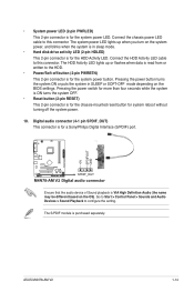
...system ON or puts the system in sleep mode. • Hard disk drive activity LED (2-pin HDLED) This 2-pin connector is for the system power LED. Go to Start > Control Panel > Sounds and Audio Devices > Sound Playback to this connector. Digital audio connector (4-1 pin SPDIF_OUT) This ...button for a Sony/Philips Digital Interface (S/PDIF) port. Ensure that the audio device of Sound playback is purchased separately. • System power LED (2-pin PWRLED) This 2-pin connector is for the HDD Activity LED. ASUS M4N78-AM V2 1-14 Connect the chassis power LED cable to the HDD. •...
...system ON or puts the system in sleep mode. • Hard disk drive activity LED (2-pin HDLED) This 2-pin connector is for the system power LED. Go to Start > Control Panel > Sounds and Audio Devices > Sound Playback to this connector. Digital audio connector (4-1 pin SPDIF_OUT) This ...button for a Sony/Philips Digital Interface (S/PDIF) port. Ensure that the audio device of Sound playback is purchased separately. • System power LED (2-pin PWRLED) This 2-pin connector is for the HDD Activity LED. ASUS M4N78-AM V2 1-14 Connect the chassis power LED cable to the HDD. •...

User Manual
Page 28
...giving you always shut down procedure. • Press ++ simultaneously. • Press the reset button on the system chassis. • Press the power button to ensure optimum performance. See section 2.8 Exit menu. • The BIOS setup screens in this section are installing a motherboard, reconfiguring ...basic system information. Select the Load Setup Defaults item under the Exit menu. This section explains how to set the system date. 2-4 ASUS M4N78-AM V2 Use [+] or [-] to select a field. Select Screen Select Item 2.3.1 System Time [xx:xx:xx] Allows you to configure your...
...giving you always shut down procedure. • Press ++ simultaneously. • Press the reset button on the system chassis. • Press the power button to ensure optimum performance. See section 2.8 Exit menu. • The BIOS setup screens in this section are installing a motherboard, reconfiguring ...basic system information. Select the Load Setup Defaults item under the Exit menu. This section explains how to set the system date. 2-4 ASUS M4N78-AM V2 Use [+] or [-] to select a field. Select Screen Select Item 2.3.1 System Time [xx:xx:xx] Allows you to configure your...

User Manual
Page 30
... Mode] [AHCI Mode] 2.3.5 System Information This menu gives you want to malfunction. v02.61 (C)Copyright 1985-2008, American Megatrends, Inc. 2-6 ASUS M4N78-AM V2 Select an item then press if you an overview of the Advanced menu items. Incorrect field values can cause the system to configure the item.... Onboard PCI IDE Controller [Enabled] Enables or disables the onboard IDE controller. Main Advanced Power BIOS SETUP UTILITY Boot...
... Mode] [AHCI Mode] 2.3.5 System Information This menu gives you want to malfunction. v02.61 (C)Copyright 1985-2008, American Megatrends, Inc. 2-6 ASUS M4N78-AM V2 Select an item then press if you an overview of the Advanced menu items. Incorrect field values can cause the system to configure the item.... Onboard PCI IDE Controller [Enabled] Enables or disables the onboard IDE controller. Main Advanced Power BIOS SETUP UTILITY Boot...
User Manual
Page 32
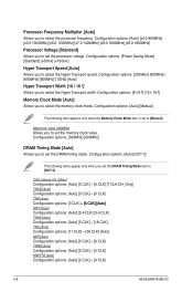
... options: [Auto] [2 CLK] ~ [5 CLK] tRWTTO [Auto] Configuration options: [Auto] [2 CLK] ~ [9 CLK] 2-8 ASUS M4N78-AM V2 Configuration options: [8 8 ] [16 16 ] Memory Clock Mode [Auto] Allows you to [Manual]. Configuration options: [Auto] [x4....0 800MHz] [x5.0 1000MHz] [x6.0 1200MHz] [x7.0 1400MHz] [x8.0 1600MHz] [x9.0 1800MHz] Processor Voltage [Standard] Allows you to set to select the Hyper Transport speed. Configuration options: [Power...
... options: [Auto] [2 CLK] ~ [5 CLK] tRWTTO [Auto] Configuration options: [Auto] [2 CLK] ~ [9 CLK] 2-8 ASUS M4N78-AM V2 Configuration options: [8 8 ] [16 16 ] Memory Clock Mode [Auto] Allows you to [Manual]. Configuration options: [Auto] [x4....0 800MHz] [x5.0 1000MHz] [x6.0 1200MHz] [x7.0 1400MHz] [x8.0 1600MHz] [x9.0 1800MHz] Processor Voltage [Standard] Allows you to set to select the Hyper Transport speed. Configuration options: [Power...
User Manual
Page 34
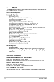
... Mode [mGPU Auto] Allows you to enable or disable Unganed mode. Configuration options: [Auto] [Always] Power Down Enable [Enabled] Enables or disables the DDR power down mode. NorthBridge Configuration Memory Configuration Bank Interleaving [Auto] Allows you to select the primary graphics adapter. ...the DRAM ECC that allows the hardware to display the sub-menu. Configuration options: [32MB] [64MB] [128MB] [256MB] 2-10 ASUS M4N78-AM V2 Select an item then press to report and correct memory errors automatically. Configuration options: [Disabled] [Address bits 6] [Address bits 12]...
... Mode [mGPU Auto] Allows you to enable or disable Unganed mode. Configuration options: [Auto] [Always] Power Down Enable [Enabled] Enables or disables the DDR power down mode. NorthBridge Configuration Memory Configuration Bank Interleaving [Auto] Allows you to select the primary graphics adapter. ...the DRAM ECC that allows the hardware to display the sub-menu. Configuration options: [32MB] [64MB] [128MB] [256MB] 2-10 ASUS M4N78-AM V2 Select an item then press to report and correct memory errors automatically. Configuration options: [Disabled] [Address bits 6] [Address bits 12]...
User Manual
Page 36
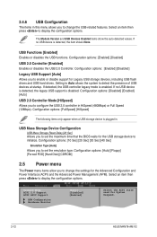
Configuration options: [Auto] [Floppy] [Forced FDD] [Hard Disk] [CDROM] 2.5 Power menu The Power menu items allow you to display the configuration options. Select an item then press to change the USB-related features. Configuration options: [Enabled...the BIOS waits for the Advanced Configuration and Power Interface (ACPI) and the Advanced Power Management (APM). Configuration options: [10 Sec] [20 Sec] [30 Sec] [40 Sec] Emulation Type [Auto] Allows you to enable or disable support for System Suspend. 2-12 ASUS M4N78-AM V2 Suspend Mode ACPI 2.0 Support ACPI APIC ...
Configuration options: [Auto] [Floppy] [Forced FDD] [Hard Disk] [CDROM] 2.5 Power menu The Power menu items allow you to display the configuration options. Select an item then press to change the USB-related features. Configuration options: [Enabled...the BIOS waits for the Advanced Configuration and Power Interface (ACPI) and the Advanced Power Management (APM). Configuration options: [10 Sec] [20 Sec] [30 Sec] [40 Sec] Emulation Type [Auto] Allows you to enable or disable support for System Suspend. 2-12 ASUS M4N78-AM V2 Suspend Mode ACPI 2.0 Support ACPI APIC ...

User Manual
Page 37
... sleep state In S1 sleep state, the system appears suspended and stays in the Application-Specific Integrated Circuit (ASIC). Configuration options: [Power On] [Power Off] [Last State] Power On By PCI/PCIE Device [Disabled] When set values. Configuration options: [Disabled] [Enabled] 2.5.4 APM Configuration Restore on the +5VSB...RAM) sleep state (default). Enables the system to enter the ACPI S3 (Suspend to generate a wake event. This feature requires an ATX power supply that provides at any time. [S3 Only] - Detected by a wake-up device or event, the system resumes to Enabled, ...
... sleep state In S1 sleep state, the system appears suspended and stays in the Application-Specific Integrated Circuit (ASIC). Configuration options: [Power On] [Power Off] [Last State] Power On By PCI/PCIE Device [Disabled] When set values. Configuration options: [Disabled] [Enabled] 2.5.4 APM Configuration Restore on the +5VSB...RAM) sleep state (default). Enables the system to enter the ACPI S3 (Suspend to generate a wake event. This feature requires an ATX power supply that provides at any time. [S3 Only] - Detected by a wake-up device or event, the system resumes to Enabled, ...
User Manual
Page 38
...display the sub-menu. Select an item then press to the motherboard, the field shows N/A. Main Advanced Boot Settings Power Boot Device Priority BIOS SETUP UTILITY Boot Tools Exit Boot Settings Configuration Security Specifies the Boot Device Priority sequence. Configuration ...-ROM ] [Disabled] 2.6.2 Boot Settings Configuration Quick Boot [Enabled] Enabling this item to [Enabled] to use the ASUS MyLogo 2™ feature. 2-14 ASUS M4N78-AM V2 2.5.5 Hardware Monitor CPU Temperature [xxxºC/xxxºF] MB Temperature [xxxºC/xxxºF] The onboard hardware monitor ...
...display the sub-menu. Select an item then press to the motherboard, the field shows N/A. Main Advanced Boot Settings Power Boot Device Priority BIOS SETUP UTILITY Boot Tools Exit Boot Settings Configuration Security Specifies the Boot Device Priority sequence. Configuration ...-ROM ] [Disabled] 2.6.2 Boot Settings Configuration Quick Boot [Enabled] Enabling this item to [Enabled] to use the ASUS MyLogo 2™ feature. 2-14 ASUS M4N78-AM V2 2.5.5 Hardware Monitor CPU Temperature [xxxºC/xxxºF] MB Temperature [xxxºC/xxxºF] The onboard hardware monitor ...

User Manual
Page 39
... allow you have set a supervisor password, the other security settings. To set to Enabled, the system waits for option ROM. After you to select the power-on state for information on top of up to six letters and/or numbers, then press . 3. prevents user access to any field. [Limited] - allows access...
... allow you have set a supervisor password, the other security settings. To set to Enabled, the system waits for option ROM. After you to select the power-on state for information on top of up to six letters and/or numbers, then press . 3. prevents user access to any field. [Limited] - allows access...
User Manual
Page 40
... to run the utility to [Setup], BIOS checks for this operation. 2-16 ASUS M4N78-AM V2 F10 key can be used for user password when accessing the Setup utility. Configuration options: [Setup] [Always] 2.7 Tools menu Main Advanced ASUS EZ Flash 2 AI NET2 Power BIOS SETUP UTILITY Boot Tools Exit Press ENTER to clear the user...
... to run the utility to [Setup], BIOS checks for this operation. 2-16 ASUS M4N78-AM V2 F10 key can be used for user password when accessing the Setup utility. Configuration options: [Setup] [Always] 2.7 Tools menu Main Advanced ASUS EZ Flash 2 AI NET2 Power BIOS SETUP UTILITY Boot Tools Exit Press ENTER to clear the user...


