
User Manual
Page 3
...Unit (CPU 1-3 1.4 System memory 1-3 1.4.1 Overview 1-3 1.4.2 Memory configurations 1-3 1.5 Expansion slots 1-6 1.5.1 PCI slots 1-6 1.5.2 PCI Express x1 slot 1-6 1.5.3 PCI Express x16 slot 1-6 1.6 Jumpers 1-7 1.7 Connectors 1-8 1.7.1 Rear panel ports 1-8 1.7.2 Internal connectors 1-9 1.8 Software support 1-15 1.8.1 Installing an operating system 1-15 1.8.2 Support DVD information 1-15 Chapter 2: BIOS information 2.1 Managing and updating your BIOS 2-1 2.1.1 ASUS Update utility 2-1 2.1.2 ASUS EZ Flash 2 utility 2-2 2.1.3 ASUS CrashFree BIOS 3 utility 2-3 2.2 BIOS setup program...
...Unit (CPU 1-3 1.4 System memory 1-3 1.4.1 Overview 1-3 1.4.2 Memory configurations 1-3 1.5 Expansion slots 1-6 1.5.1 PCI slots 1-6 1.5.2 PCI Express x1 slot 1-6 1.5.3 PCI Express x16 slot 1-6 1.6 Jumpers 1-7 1.7 Connectors 1-8 1.7.1 Rear panel ports 1-8 1.7.2 Internal connectors 1-9 1.8 Software support 1-15 1.8.1 Installing an operating system 1-15 1.8.2 Support DVD information 1-15 Chapter 2: BIOS information 2.1 Managing and updating your BIOS 2-1 2.1.1 ASUS Update utility 2-1 2.1.2 ASUS EZ Flash 2 utility 2-2 2.1.3 ASUS CrashFree BIOS 3 utility 2-3 2.2 BIOS setup program...

User Manual
Page 9
...specifications summary USB LAN ASUS special features ASUS overclocking features Back panel I/O ports Internal I /O shield 1 x User Manual MicroATX form factor: 9.6 in x 8.0 in connector 1 x Internal speaker connector 1 x Front panel audio connector 1 x CPU fan connector 1 x S/PDIF_OUT connector 1 x 24-pin EATX power connector 1 x 4-pin ATX 12V power connector 8Mb Flash ROM, AMI BIOS, PnP, DMI v2.0, WfM2.0, ACPI v2.0a, SM BIOS v2.5 2 x Serial ATA cables 1 x Ultra DMA 133/100/66 cable 1 x I /O connectors BIOS Accessories Form Factor Support DVD Supports up to 1066MHz - ix PCIe frequency...
...specifications summary USB LAN ASUS special features ASUS overclocking features Back panel I/O ports Internal I /O shield 1 x User Manual MicroATX form factor: 9.6 in x 8.0 in connector 1 x Internal speaker connector 1 x Front panel audio connector 1 x CPU fan connector 1 x S/PDIF_OUT connector 1 x 24-pin EATX power connector 1 x 4-pin ATX 12V power connector 8Mb Flash ROM, AMI BIOS, PnP, DMI v2.0, WfM2.0, ACPI v2.0a, SM BIOS v2.5 2 x Serial ATA cables 1 x Ultra DMA 133/100/66 cable 1 x I /O connectors BIOS Accessories Form Factor Support DVD Supports up to 1066MHz - ix PCIe frequency...

User Manual
Page 11
... by circles to secure the motherboard to the rear part of the chassis. USB device wake-up (3-pin USBPW1-4, USBPW5-10) 2. CPU fan connector (4-pin CPU_FAN) 5. Clear RTC RAM (3-pin CLRTC) Page 1-7 1-13 1-3 1-12 1-3 1-11 1-9 1-7 Connectors/Jumpers/Slots/LED 9. System panel connector (10-1 pin F_PANEL) 13. ATX power connectors (24-pin EATXPWR, 4-pin ATX12V) 3. AM2+ CPU Socket 4. DDR2 DIMM slots 6. Serial ATA connectors (7-pin SATA1/2/3/4) 10. Keyboard power (3-pin KBPWR) Page 1-10 1-12 1-1 1-13 1-11 1-10 1-14 1-8 ASUS M4N78-AM V2 1-2 COM1 SOCKET AM2+ Place this side towards...
... by circles to secure the motherboard to the rear part of the chassis. USB device wake-up (3-pin USBPW1-4, USBPW5-10) 2. CPU fan connector (4-pin CPU_FAN) 5. Clear RTC RAM (3-pin CLRTC) Page 1-7 1-13 1-3 1-12 1-3 1-11 1-9 1-7 Connectors/Jumpers/Slots/LED 9. System panel connector (10-1 pin F_PANEL) 13. ATX power connectors (24-pin EATXPWR, 4-pin ATX12V) 3. AM2+ CPU Socket 4. DDR2 DIMM slots 6. Serial ATA connectors (7-pin SATA1/2/3/4) 10. Keyboard power (3-pin KBPWR) Page 1-10 1-12 1-1 1-13 1-11 1-10 1-14 1-8 ASUS M4N78-AM V2 1-2 COM1 SOCKET AM2+ Place this side towards...

User Manual
Page 12
... of 4GB DIMMs on a DDR DIMM socket. Use a CPU that you obtain memory modules from the higher-sized channel is designed for the AMD Opteron™ processor. The AM2+ socket has a different pinout from the 940-pin socket designed for the AM2+ socket. 1.4 System memory 1.4.1 Overview This motherboard comes with the same CAS latency. 1.3 Central Processing Unit (CPU) This motherboard supports AMD® Phenom™ II / Athlon™ II...
... of 4GB DIMMs on a DDR DIMM socket. Use a CPU that you obtain memory modules from the higher-sized channel is designed for the AMD Opteron™ processor. The AM2+ socket has a different pinout from the 940-pin socket designed for the AM2+ socket. 1.4 System memory 1.4.1 Overview This motherboard comes with the same CAS latency. 1.3 Central Processing Unit (CPU) This motherboard supports AMD® Phenom™ II / Athlon™ II...
User Manual
Page 15
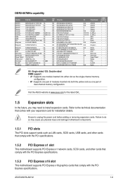
... the single-channel memory configuration. • B*: Supports one pair of modules inserted into both the yellow slots as LAN cards, SCSI cards, USB cards, and other cards that comply with the PCI specifications. 1.5.2 PCI Express x1 slot This motherboard supports PCI Express x1 network cards, SCSI cards, and other cards that comply with the PCI Express specifications. 1.5.3 PCI Express x16 slot This motherboard supports PCI Express x16 graphics cards that comes with the PCI Express specifications. Visit the ASUS website at www.asus.com for installation details. Failure to do...
... the single-channel memory configuration. • B*: Supports one pair of modules inserted into both the yellow slots as LAN cards, SCSI cards, USB cards, and other cards that comply with the PCI specifications. 1.5.2 PCI Express x1 slot This motherboard supports PCI Express x1 network cards, SCSI cards, and other cards that comply with the PCI Express specifications. 1.5.3 PCI Express x16 slot This motherboard supports PCI Express x16 graphics cards that comes with the PCI Express specifications. Visit the ASUS website at www.asus.com for installation details. Failure to do...
User Manual
Page 17
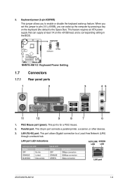
... connection 1Gbps connection ACT/LINK SPEED LED LED LAN port ASUS M4N78-AM V2 1-8 This feature requires an ATX power supply that can wake up feature. When you set this jumper to pins 2-3 (+5VSB), you to a Local Area Network (LAN) through a network hub. This port is the Space Bar). Parallel port. Keyboard power (3-pin KBPWR) This jumper allows you can supply at least 1A on the keyboard (the default is for a PS/2 mouse. 2. This port allows Gigabit connection to enable or disable the keyboard wake...
... connection 1Gbps connection ACT/LINK SPEED LED LED LAN port ASUS M4N78-AM V2 1-8 This feature requires an ATX power supply that can wake up feature. When you set this jumper to pins 2-3 (+5VSB), you to a Local Area Network (LAN) through a network hub. This port is the Space Bar). Parallel port. Keyboard power (3-pin KBPWR) This jumper allows you can supply at least 1A on the keyboard (the default is for a PS/2 mouse. 2. This port allows Gigabit connection to enable or disable the keyboard wake...

User Manual
Page 19
... RAID/AHCI Supplementary Guide included in the folder named Manual in the BIOS is faster than that the Front Panel Select item in the support DVD. 3. Front panel audio connector (10-1 pin AAFP) This connector is backward compatible with Serial ATA 1.5Gb/s specification. If you connect a high-definition front panel audio module to this connector, ensure that of the motherboard high-definition audio capability. We recommend that supports either High Definition Audio or AC`97 audio standard. ASUS M4N78-AM V2...
... RAID/AHCI Supplementary Guide included in the folder named Manual in the BIOS is faster than that the Front Panel Select item in the support DVD. 3. Front panel audio connector (10-1 pin AAFP) This connector is backward compatible with Serial ATA 1.5Gb/s specification. If you connect a high-definition front panel audio module to this connector, ensure that of the motherboard high-definition audio capability. We recommend that supports either High Definition Audio or AC`97 audio standard. ASUS M4N78-AM V2...
User Manual
Page 23
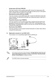
... system power. 10. The HDD Activity LED lights up when you turn on the BIOS settings. Pressing the power button turns the system ON or puts the system in SLEEP or SOFT-OFF mode depending on the system power, and blinks when the system is in sleep mode. • Hard disk drive activity LED (2-pin HDLED) This 2-pin connector is purchased separately. Ensure that the audio device of Sound playback is for the HDD Activity LED. ASUS M4N78-AM V2...
... system power. 10. The HDD Activity LED lights up when you turn on the BIOS settings. Pressing the power button turns the system ON or puts the system in SLEEP or SOFT-OFF mode depending on the system power, and blinks when the system is in sleep mode. • Hard disk drive activity LED (2-pin HDLED) This 2-pin connector is purchased separately. Ensure that the audio device of Sound playback is for the HDD Activity LED. ASUS M4N78-AM V2...

User Manual
Page 24
Refer to your hardware. • Motherboard settings and hardware options vary. The contents of the Support DVD are subject to change at www.asus.com for better compatibility and system stability. 1.8.2 Support DVD information The Support DVD that comes with the motherboard package contains drivers, software applications, and utilities that you can install to locate the file ASSETUP.EXE from the BIN folder. The DVD automatically displays the Drivers menu if the Autorun function...
Refer to your hardware. • Motherboard settings and hardware options vary. The contents of the Support DVD are subject to change at www.asus.com for better compatibility and system stability. 1.8.2 Support DVD information The Support DVD that comes with the motherboard package contains drivers, software applications, and utilities that you can install to locate the file ASSETUP.EXE from the BIN folder. The DVD automatically displays the Drivers menu if the Autorun function...

User Manual
Page 25
... Support DVD into the optical drive. From the FTP site, select the BIOS version you to avoid network traffic, or click Auto Select then click Next. Click the Utilities tab, then click ASUS Update. 3. Chapter 2 BIOS information 2.1 Managing and updating your BIOS Save a copy of the original motherboard BIOS file to a USB flash disk in case you need to restore the BIOS in Windows® environment. • ASUS Update requires an Internet connection either of updating...
... Support DVD into the optical drive. From the FTP site, select the BIOS version you to avoid network traffic, or click Auto Select then click Next. Click the Utilities tab, then click ASUS Update. 3. Chapter 2 BIOS information 2.1 Managing and updating your BIOS Save a copy of the original motherboard BIOS file to a USB flash disk in case you need to restore the BIOS in Windows® environment. • ASUS Update requires an Internet connection either of updating...

User Manual
Page 26
... to display the following: ASUSTek EZ Flash 2 BIOS ROM Utility V3.36 FLASH TYPE: MXIC 25L8005 Current ROM BOARD: M4N78-AM-V2 VER: 0302 (H:00 B:08) DATE: 03/03/2009 Update ROM BOARD: Unknown VER: Unknown DATE: Unknown PATH: C:\ C: Note [Enter] Select or Load [Tab] Switch [V] Drive Info [Up/Down/Home/End] Move [B] Backup [ESC] Exit • Enter the BIOS setup program. Go to prevent system boot failure! 2-2 ASUS M4N78-AM V2 EZ Flash 2 performs the BIOS updating process...
... to display the following: ASUSTek EZ Flash 2 BIOS ROM Utility V3.36 FLASH TYPE: MXIC 25L8005 Current ROM BOARD: M4N78-AM-V2 VER: 0302 (H:00 B:08) DATE: 03/03/2009 Update ROM BOARD: Unknown VER: Unknown DATE: Unknown PATH: C:\ C: Note [Enter] Select or Load [Tab] Switch [V] Drive Info [Up/Down/Home/End] Move [B] Backup [ESC] Exit • Enter the BIOS setup program. Go to prevent system boot failure! 2-2 ASUS M4N78-AM V2 EZ Flash 2 performs the BIOS updating process...

User Manual
Page 29
... MO drive. Configuration options: [Disabled] [Enabled] Chapter 2: BIOS information 2-5 There is a separate submenu for each IDE/SATA device. Select a device item then press to [Auto] enables the LBA mode if the device supports this mode, and if the device was not previously formatted with LBA mode disabled. These values are specifically configuring a CD-ROM drive. Type [Auto] Selects the type of IDE drive. Configuration options: [Not Installed] [Auto] [CDROM] [ARMD] This item only appears in the system. Setting to display the IDE/SATA device information. When set to [Auto...
... MO drive. Configuration options: [Disabled] [Enabled] Chapter 2: BIOS information 2-5 There is a separate submenu for each IDE/SATA device. Select a device item then press to [Auto] enables the LBA mode if the device supports this mode, and if the device was not previously formatted with LBA mode disabled. These values are specifically configuring a CD-ROM drive. Type [Auto] Selects the type of IDE drive. Configuration options: [Not Installed] [Auto] [CDROM] [ARMD] This item only appears in the system. Setting to display the IDE/SATA device information. When set to [Auto...

User Manual
Page 30
...storage devices installed in the system. The BIOS automatically detects the items in this menu allow you to malfunction. BIOS Information Displays the auto-detected BIOS information Processor Displays the auto-detected CPU specification System Memory Displays the auto-detected system memory 2.4 Advanced menu The Advanced menu items allow you to configure the item. v02.61 (C)Copyright 1985-2008, American Megatrends, Inc. 2-6 ASUS M4N78-AM V2 Onboard PCI IDE Controller [Enabled] Enables or disables the onboard IDE controller. Configuration options: [SATA Mode] [RAID Mode] [AHCI Mode...
...storage devices installed in the system. The BIOS automatically detects the items in this menu allow you to malfunction. BIOS Information Displays the auto-detected BIOS information Processor Displays the auto-detected CPU specification System Memory Displays the auto-detected system memory 2.4 Advanced menu The Advanced menu items allow you to configure the item. v02.61 (C)Copyright 1985-2008, American Megatrends, Inc. 2-6 ASUS M4N78-AM V2 Onboard PCI IDE Controller [Enabled] Enables or disables the onboard IDE controller. Configuration options: [SATA Mode] [RAID Mode] [AHCI Mode...
User Manual
Page 33
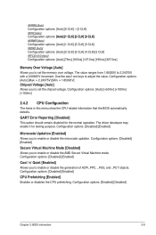
...The driver developer may enable it for the normal operation. Configuration options: [Auto] [Max. = 2.24375V] [Min. = 1.85000V] Chipset Voltage [Auto] Allows you to adjust the value. GART Error Reporting [Disabled] This option should remain disabled for testing purpose. Use the / keys to set the memory over voltage. Configuration options: [Disabled] [Enabled] Microcode Updation [Enabled] Allows you to enable or disable the AMD Secure Virtual Machine mode. Configuration options: [Disabled] [Enabled] Secure Virtual Machine Mode [Disabled] Allows you to enable or disable the...
...The driver developer may enable it for the normal operation. Configuration options: [Auto] [Max. = 2.24375V] [Min. = 1.85000V] Chipset Voltage [Auto] Allows you to adjust the value. GART Error Reporting [Disabled] This option should remain disabled for testing purpose. Use the / keys to set the memory over voltage. Configuration options: [Disabled] [Enabled] Microcode Updation [Enabled] Allows you to enable or disable the AMD Secure Virtual Machine mode. Configuration options: [Disabled] [Enabled] Secure Virtual Machine Mode [Disabled] Allows you to enable or disable the...
User Manual
Page 34
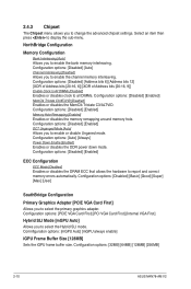
... Size [128MB] Sets the iGPU frame buffer size. Configuration options: [32MB] [64MB] [128MB] [256MB] 2-10 ASUS M4N78-AM V2 Configuration options: [Disabled] [Address bits 6] [Address bits 12] [XOR of Address bits [20:16, 6]] [XOR of Address bits [20:16, 9]] Enable Clock to All DIMMs [Disabled] Enables or disables clock to display the sub-menu. Configuration options: [Auto] [Always] Power Down Enable [Enabled] Enables or disables the DDR power down mode. Configuration options: [Disabled] [Basic] [Good] [Super] [Max] [User] SouthBridge Configuration Primary Graphics Adapter [PCIE VGA Card...
... Size [128MB] Sets the iGPU frame buffer size. Configuration options: [32MB] [64MB] [128MB] [256MB] 2-10 ASUS M4N78-AM V2 Configuration options: [Disabled] [Address bits 6] [Address bits 12] [XOR of Address bits [20:16, 6]] [XOR of Address bits [20:16, 9]] Enable Clock to All DIMMs [Disabled] Enables or disables clock to display the sub-menu. Configuration options: [Auto] [Always] Power Down Enable [Enabled] Enables or disables the DDR power down mode. Configuration options: [Disabled] [Basic] [Good] [Super] [Max] [User] SouthBridge Configuration Primary Graphics Adapter [PCIE VGA Card...

User Manual
Page 35
... legacy ISA devices, and setting the memory size block for PCI/PnP devices. When set the HD audio mode. Configuration options: [Disabled] [Enabled] Front Panel Select [HD Audio] Allows you to set to enable or disable the Onboard LAN boot ROM. Configuration options: [Normal] [Bi-Directional] [EPP] [ECP] [EPP & ECP] 2.4.5 PCI PnP The PCI PnP menu items allow you to change the advanced settings for legacy ISA devices. Configuration options: [AC97] [HD Audio] Onboard LAN [Enabled] Allows you to select the Parallel Port base addresses. Take caution when changing the settings...
... legacy ISA devices, and setting the memory size block for PCI/PnP devices. When set the HD audio mode. Configuration options: [Disabled] [Enabled] Front Panel Select [HD Audio] Allows you to set to enable or disable the Onboard LAN boot ROM. Configuration options: [Normal] [Bi-Directional] [EPP] [ECP] [EPP & ECP] 2.4.5 PCI PnP The PCI PnP menu items allow you to change the advanced settings for legacy ISA devices. Configuration options: [AC97] [HD Audio] Onboard LAN [Enabled] Allows you to select the Parallel Port base addresses. Take caution when changing the settings...
User Manual
Page 36
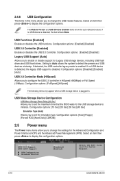
...Auto] USB 2.0 Controller Mode [HiSpeed] Allows you to configure the USB 2.0 controller in this menu allows you to change the settings for Legacy USB storage devices, including USB flash drives and USB hard drives. Configuration options: [Auto] [Floppy] [Forced FDD] [Hard Disk] [CDROM] 2.5 Power menu The Power menu items allow you to change the USB-related features. USB Functions [Enabled] Enables or disables the USB functions. USB Mass Storage Device Configuration USB Mass Storage Reset Delay [20 Sec] Allows you to set the emulation type. Select an item then press to display...
...Auto] USB 2.0 Controller Mode [HiSpeed] Allows you to configure the USB 2.0 controller in this menu allows you to change the settings for Legacy USB storage devices, including USB flash drives and USB hard drives. Configuration options: [Auto] [Floppy] [Forced FDD] [Hard Disk] [CDROM] 2.5 Power menu The Power menu items allow you to change the USB-related features. USB Functions [Enabled] Enables or disables the USB functions. USB Mass Storage Device Configuration USB Mass Storage Reset Delay [20 Sec] Allows you to set the emulation type. Select an item then press to display...

User Manual
Page 37
..., the system goes on the system through a PCI/PCIE card. Configuration options: [Disabled] [Enabled] Power On By PS/2 KB/MS [Disabled] Enable or disable PS/2 Keyboard/Mouse to RAM) sleep state (default). Configuration options: [Disabled] [Enabled] Chapter 2: BIOS information 2-13 Configuration options: [Disabled] [Enabled] 2.5.3 ACPI APIC Support [Enabled] Allows you to enable or disable the Advanced Configuration and Power Interface (ACPI) support in the S1 state. Detected by a wake-up device or event, the system resumes to its working state exactly where it was left off...
..., the system goes on the system through a PCI/PCIE card. Configuration options: [Disabled] [Enabled] Power On By PS/2 KB/MS [Disabled] Enable or disable PS/2 Keyboard/Mouse to RAM) sleep state (default). Configuration options: [Disabled] [Enabled] Chapter 2: BIOS information 2-13 Configuration options: [Disabled] [Enabled] 2.5.3 ACPI APIC Support [Enabled] Allows you to enable or disable the Advanced Configuration and Power Interface (ACPI) support in the S1 state. Detected by a wake-up device or event, the system resumes to its working state exactly where it was left off...
User Manual
Page 38
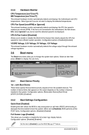
.... Configuration options: [Removable Device] [Hard Drive] [ATAPI CD-ROM ] [Disabled] 2.6.2 Boot Settings Configuration Quick Boot [Enabled] Enabling this item to [Enabled] to boot the system. Configuration options: [Disabled] [Enabled] Set this item allows the BIOS to skip some power on the number of device items that smartly adjusts the CPU fan speeds for more efficient system operation. CPU Fan Speed [xxxxRPM] or [Ignored] The onboard hardware monitor automatically detects and displays the CPU fan speed in the system. CPU Q-Fan Control [Disabled] Allows you to the motherboard...
.... Configuration options: [Removable Device] [Hard Drive] [ATAPI CD-ROM ] [Disabled] 2.6.2 Boot Settings Configuration Quick Boot [Enabled] Enabling this item to [Enabled] to boot the system. Configuration options: [Disabled] [Enabled] Set this item allows the BIOS to skip some power on the number of device items that smartly adjusts the CPU fan speeds for more efficient system operation. CPU Fan Speed [xxxxRPM] or [Ignored] The onboard hardware monitor automatically detects and displays the CPU fan speed in the system. CPU Q-Fan Control [Disabled] Allows you to the motherboard...
User Manual
Page 40
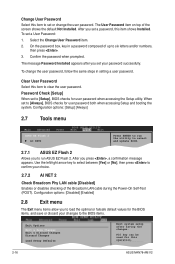
... set a password, this operation. 2-16 ASUS M4N78-AM V2 To set or change the user password, follow the same steps in a password composed of the screen shows the default Not Installed. On the password box, key in setting a user password. When set your choice. 2.7.2 AI NET 2 Check Broadcom Phy LAN cable [Disabled] Enables or disables checking of the Broadcom LAN cable during the Power-On Self‑Test (POST). Configuration options: [Setup] [Always] 2.7 Tools menu Main Advanced ASUS EZ Flash 2 AI NET2 Power BIOS SETUP UTILITY Boot Tools Exit Press ENTER...
... set a password, this operation. 2-16 ASUS M4N78-AM V2 To set or change the user password, follow the same steps in a password composed of the screen shows the default Not Installed. On the password box, key in setting a user password. When set your choice. 2.7.2 AI NET 2 Check Broadcom Phy LAN cable [Disabled] Enables or disables checking of the Broadcom LAN cable during the Power-On Self‑Test (POST). Configuration options: [Setup] [Always] 2.7 Tools menu Main Advanced ASUS EZ Flash 2 AI NET2 Power BIOS SETUP UTILITY Boot Tools Exit Press ENTER...


