User Manual
Page 4
Contents 1.11 Software support 1-28 1.11.1 Installing an operating system 1-28 1.11.2 Support DVD information 1-28 Chapter 2: BIOS information 2.1 Managing and updating your BIOS 2-1 2.1.1 ASUS Update utility 2-1 2.1.2 ASUS EZ Flash 2 utility 2-2 2.1.3 ASUS CrashFree BIOS utility 2-3 2.2 BIOS setup program 2-4 2.2.1 BIOS menu screen 2-5 2.2.3 Navigation keys 2-5 2.2.2 Menu bar 2-5 2.2.4 Menu items 2-6 2.2.5 Submenu items 2-6 2.2.6 Configuration fields 2-6 2.2.7 Pop-up window 2-6 2.2.8 Scroll bar 2-6 2.2.9 General help 2-6 2.3 Main...
Contents 1.11 Software support 1-28 1.11.1 Installing an operating system 1-28 1.11.2 Support DVD information 1-28 Chapter 2: BIOS information 2.1 Managing and updating your BIOS 2-1 2.1.1 ASUS Update utility 2-1 2.1.2 ASUS EZ Flash 2 utility 2-2 2.1.3 ASUS CrashFree BIOS utility 2-3 2.2 BIOS setup program 2-4 2.2.1 BIOS menu screen 2-5 2.2.3 Navigation keys 2-5 2.2.2 Menu bar 2-5 2.2.4 Menu items 2-6 2.2.5 Submenu items 2-6 2.2.6 Configuration fields 2-6 2.2.7 Pop-up window 2-6 2.2.8 Scroll bar 2-6 2.2.9 General help 2-6 2.3 Main...

User Manual
Page 7
..., and staples away from connectors, slots, sockets and circuitry. • Avoid dust, humidity, and temperature extremes. Detailed descriptions of the BIOS parameters are using an adapter or extension cord. vii Operation safety • Before installing the motherboard and adding devices on a stable surface.... about the voltage of the motherboard and the new technology it supports. • Chapter 2: BIOS information This chapter tells how to change system settings through the BIOS Setup menus. How this guide This user guide contains the information you are also provided. Contact...
..., and staples away from connectors, slots, sockets and circuitry. • Avoid dust, humidity, and temperature extremes. Detailed descriptions of the BIOS parameters are using an adapter or extension cord. vii Operation safety • Before installing the motherboard and adding devices on a stable surface.... about the voltage of the motherboard and the new technology it supports. • Chapter 2: BIOS information This chapter tells how to change system settings through the BIOS Setup menus. How this guide This user guide contains the information you are also provided. Contact...
User Manual
Page 10
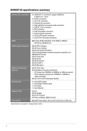
... connector 1 x 4-pin ATX 12V power connector BIOS ASUS special features ASUS overclocking features 8Mb Flash ROM, AMI BIOS, PnP, DMI2.0, WfM2.0, ACPI2.0a, SM BIOS 2.5 ASUS EPU-4 Engine ASUS Core Unlocker ASUS Anti-Surge Protection 100% All high quality conductive polymer capacitors (on M4N68T-M V2 only) ASUS Turbo Key ASUS Q-Fan ASUS EZ Flash 2 ASUS AI NET 2 ASUS MyLogo 2 ASUS Turbo Key SFS (Stepless Frequency Selection...
... connector 1 x 4-pin ATX 12V power connector BIOS ASUS special features ASUS overclocking features 8Mb Flash ROM, AMI BIOS, PnP, DMI2.0, WfM2.0, ACPI2.0a, SM BIOS 2.5 ASUS EPU-4 Engine ASUS Core Unlocker ASUS Anti-Surge Protection 100% All high quality conductive polymer capacitors (on M4N68T-M V2 only) ASUS Turbo Key ASUS Q-Fan ASUS EZ Flash 2 ASUS AI NET 2 ASUS MyLogo 2 ASUS Turbo Key SFS (Stepless Frequency Selection...
User Manual
Page 13
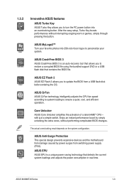
... boost by power surges from a USB flash disk before entering the OS. ASUS M4N68T-M Series 1-3 ASUS CrashFree BIOS 3 ASUS CrashFree BIOS 3 is a unique power saving technology that contains the BIOS file. ASUS Q-Fan ASUS Q-Fan technology intelligently adjusts the CPU fan speed according to system loading to ...setup, Turbo Key boosts performances without performing complicated BIOS changes. ASUS MyLogo2™ Turn your system. ASUS EZ Flash 2 ASUS EZ Flash 2 allows you to update the BIOS from switching power supply (PSU). ASUS EPU ASUS EPU is an auto-recovery tool that allows you...
... boost by power surges from a USB flash disk before entering the OS. ASUS M4N68T-M Series 1-3 ASUS CrashFree BIOS 3 ASUS CrashFree BIOS 3 is a unique power saving technology that contains the BIOS file. ASUS Q-Fan ASUS Q-Fan technology intelligently adjusts the CPU fan speed according to system loading to ...setup, Turbo Key boosts performances without performing complicated BIOS changes. ASUS MyLogo2™ Turn your system. ASUS EZ Flash 2 ASUS EZ Flash 2 allows you to update the BIOS from switching power supply (PSU). ASUS EPU ASUS EPU is an auto-recovery tool that allows you...

User Manual
Page 14
... settings. Simply shut down and reboot the system, and the BIOS automatically restores the CPU parameters to safeguard consumers' health while minimizing the impact on the environment. 1-4 Chapter 1: Product introduction C.P.R. eliminates the need to 100 meters at 1 meter accuracy. ASUS AI NET2 ASUS AI NET2 remotely detects the cable connection immediately after you...
... settings. Simply shut down and reboot the system, and the BIOS automatically restores the CPU parameters to safeguard consumers' health while minimizing the impact on the environment. 1-4 Chapter 1: Product introduction C.P.R. eliminates the need to 100 meters at 1 meter accuracy. ASUS AI NET2 ASUS AI NET2 remotely detects the cable connection immediately after you...
User Manual
Page 17
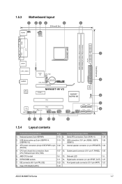
...6in) LAN1_USB12 Super I/O CPU_FAN EATXPWR Lithium Cell 3 AUDIO CMOS Power CHA_FAN RTL 8211CL -VB PCIEX16 M4N68T-M V2 PCIEX1_1 PCI1 NVIDIA® MCP68 SE 8Mb BIOS 8 CLRTC 2 SATA2 SATA4 PCI2 VIA VT1708S SB_PWR F_PANEL USB56 USB78 USB910 SATA1 SATA3 9 SPDIF_OUT SPEAKER ... 13. pin SPEAKER) 1-24 ATX12V) 4. Onboard LED 1-5 6. IDE connector (40-1 pin PRI_IDE) 1-23 15. Clear RTC RAM (CLRTC) 1-18 ASUS M4N68T-M Series 1-7 ATX power connectors (24-pin EATXPWR, 4-pin 1-22 11. Internal speaker connector (4- Front panel audio connector (10-1 pin AAFP) 1-21 8....
...6in) LAN1_USB12 Super I/O CPU_FAN EATXPWR Lithium Cell 3 AUDIO CMOS Power CHA_FAN RTL 8211CL -VB PCIEX16 M4N68T-M V2 PCIEX1_1 PCI1 NVIDIA® MCP68 SE 8Mb BIOS 8 CLRTC 2 SATA2 SATA4 PCI2 VIA VT1708S SB_PWR F_PANEL USB56 USB78 USB910 SATA1 SATA3 9 SPDIF_OUT SPEAKER ... 13. pin SPEAKER) 1-24 ATX12V) 4. Onboard LED 1-5 6. IDE connector (40-1 pin PRI_IDE) 1-23 15. Clear RTC RAM (CLRTC) 1-18 ASUS M4N68T-M Series 1-7 ATX power connectors (24-pin EATXPWR, 4-pin 1-22 11. Internal speaker connector (4- Front panel audio connector (10-1 pin AAFP) 1-21 8....

User Manual
Page 22
...or more memory on the next page 1-12 Chapter 1: Product introduction M4N68T-M Series Motherboard Qualified Vendors Lists (QVL) DDR3-1800(O.C.)MHz capability Vendor Part No. Size SS/DS Brand Chip NO. Timing DIMM (BIOS) Voltage DIMM Support A* B* DS N/A Heat-Sink Package 7-7-7-20 1....SS Corsair CM3X2G1800C8D 2048MB DS Transcend TX1800KLU-2GK 1024MB SS N/A Heat-Sink Package N/A Heat-Sink Package N/A Heat-Sink Package Timing DIMM (BIOS) Voltage DIMM Support A* B* • • • • • DDR3-1600(O.C.)MHz capability Vendor A-Data Corsair Corsair ...
...or more memory on the next page 1-12 Chapter 1: Product introduction M4N68T-M Series Motherboard Qualified Vendors Lists (QVL) DDR3-1800(O.C.)MHz capability Vendor Part No. Size SS/DS Brand Chip NO. Timing DIMM (BIOS) Voltage DIMM Support A* B* DS N/A Heat-Sink Package 7-7-7-20 1....SS Corsair CM3X2G1800C8D 2048MB DS Transcend TX1800KLU-2GK 1024MB SS N/A Heat-Sink Package N/A Heat-Sink Package N/A Heat-Sink Package Timing DIMM (BIOS) Voltage DIMM Support A* B* • • • • • DDR3-1600(O.C.)MHz capability Vendor A-Data Corsair Corsair ...

User Manual
Page 24
...-HCH9(ECC) 1024MB SS N/A Heat-Sink Package 1024MB SS N/A SEC 813HCH9 K4B1G0846D 1024MB SS N/A K4B1G0846D(ECC) 2048MB DS Micron 9GF27D9KPT 2048MB DS N/A SEC816HCH9K4B1G0846D Timing DIMM (BIOS) Voltage DIMM Support A* B* • •• 7-7-7-18 1.5~1.6V • • 9-9-9-24 1.5~1.6V • • •• • 8-8-8-21 1.5-1.6V • • 7-7-7-18 1.5~1.6V • •...
...-HCH9(ECC) 1024MB SS N/A Heat-Sink Package 1024MB SS N/A SEC 813HCH9 K4B1G0846D 1024MB SS N/A K4B1G0846D(ECC) 2048MB DS Micron 9GF27D9KPT 2048MB DS N/A SEC816HCH9K4B1G0846D Timing DIMM (BIOS) Voltage DIMM Support A* B* • •• 7-7-7-18 1.5~1.6V • • 9-9-9-24 1.5~1.6V • • •• • 8-8-8-21 1.5-1.6V • • 7-7-7-18 1.5~1.6V • •...

User Manual
Page 25
... Micron 9HF22D9KPT(ECC) Micron 8LD22D9JNL Micron 9HF22D9KPT Micron 9GF22D9KPT(ECC) N/A Heat-Sink Package Samsung SEC 901 HCF8 K4B1G0846E Samsung 846 K4B2G0846B-HCF8 Timing DIMM Voltage (BIOS) 7 7 7 7 7 1.5V 7 1.5V 7 7 7 7 7-7-7-16 1.75V DIMM Support A* B* • • • • • • • • • •... inserted into both the blue slots as one pair of dual-channel memory configuration. ASUS M4N68T-M Series 1-15 Visit the ASUS website at www.asus.com for the latest QVL. DDR3-1066MHz capability Vendor Part No. Size SS/ DS ...
... Micron 9HF22D9KPT(ECC) Micron 8LD22D9JNL Micron 9HF22D9KPT Micron 9GF22D9KPT(ECC) N/A Heat-Sink Package Samsung SEC 901 HCF8 K4B1G0846E Samsung 846 K4B2G0846B-HCF8 Timing DIMM Voltage (BIOS) 7 7 7 7 7 1.5V 7 1.5V 7 7 7 7 7-7-7-16 1.75V DIMM Support A* B* • • • • • • • • • •... inserted into both the blue slots as one pair of dual-channel memory configuration. ASUS M4N68T-M Series 1-15 Visit the ASUS website at www.asus.com for the latest QVL. DDR3-1066MHz capability Vendor Part No. Size SS/ DS ...
User Manual
Page 27
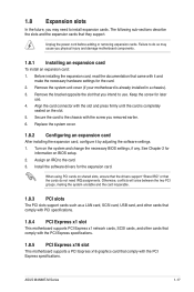
...in a chassis). 3. Before installing the expansion card, read the documentation that came with it by adjusting the software settings. 1. Turn on BIOS setup. 2. Otherwise, conflicts will arise between the two PCI groups, making the system unstable and the card inoperable. 1.8.3 PCI slots The PCI...supports a PCI Express x16 graphics card that they support. Failure to the card. 3. When using PCI cards on the slot. 5. ASUS M4N68T-M Series 1-17 Unplug the power cord before adding or removing expansion cards. Keep the screw for the expansion card. Install the software drivers...
...in a chassis). 3. Before installing the expansion card, read the documentation that came with it by adjusting the software settings. 1. Turn on BIOS setup. 2. Otherwise, conflicts will arise between the two PCI groups, making the system unstable and the card inoperable. 1.8.3 PCI slots The PCI...supports a PCI Express x16 graphics card that they support. Failure to the card. 3. When using PCI cards on the slot. 5. ASUS M4N68T-M Series 1-17 Unplug the power cord before adding or removing expansion cards. Keep the screw for the expansion card. Install the software drivers...

User Manual
Page 28
...jumper cap from pins 1-2 (default) to clear the CMOS RTC RAM data. For system failure due to overclocking. CLRTC 12 23 M4N68T-M V2 Normal (Default) Clear RTC M4N68T-M Series Clear RTC RAM To erase the RTC RAM: 1. Keep the cap on CLRTC jumper default position. After clearing the CMOS,...values. 1-18 Chapter 1: Product introduction You can automatically reset parameter settings to pins 1-2. 3. Hold down and reboot the system so the BIOS can clear the CMOS memory of date, time, and system setup parameters by erasing the CMOS RTC RAM data. Turn OFF the computer and...
...jumper cap from pins 1-2 (default) to clear the CMOS RTC RAM data. For system failure due to overclocking. CLRTC 12 23 M4N68T-M V2 Normal (Default) Clear RTC M4N68T-M Series Clear RTC RAM To erase the RTC RAM: 1. Keep the cap on CLRTC jumper default position. After clearing the CMOS,...values. 1-18 Chapter 1: Product introduction You can automatically reset parameter settings to pins 1-2. 3. Hold down and reboot the system so the BIOS can clear the CMOS memory of date, time, and system setup parameters by erasing the CMOS RTC RAM data. Turn OFF the computer and...

User Manual
Page 29
... 12 23 +5V +5VSB (Default) M4N68T-M V2 USBPW5-10 12 23 +5V +5VSB (Default) M4N68T-M Series USB Device Wake Up 3. When you set this jumper to wake up the computer by pressing a key on the +5VSB lead, and a corresponding setting in the BIOS. Set these jumpers to +5V to... S1 sleep mode (CPU stopped, DRAM refreshed, system running in reduced power mode). KBPWR 12 23 +5V +5VSB (Default) M4N68T-M V2 M4N68T-M Series Keyboard Power Setting ASUS M4N68T-M Series 1-19 2. Keyboard power (3-pin KBPWR) This jumper allows you can supply at least 1A on the keyboard (the default...
... 12 23 +5V +5VSB (Default) M4N68T-M V2 USBPW5-10 12 23 +5V +5VSB (Default) M4N68T-M Series USB Device Wake Up 3. When you set this jumper to wake up the computer by pressing a key on the +5VSB lead, and a corresponding setting in the BIOS. Set these jumpers to +5V to... S1 sleep mode (CPU stopped, DRAM refreshed, system running in reduced power mode). KBPWR 12 23 +5V +5VSB (Default) M4N68T-M V2 M4N68T-M Series Keyboard Power Setting ASUS M4N68T-M Series 1-19 2. Keyboard power (3-pin KBPWR) This jumper allows you can supply at least 1A on the keyboard (the default...
User Manual
Page 31
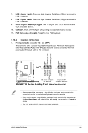
...1 PIN 1 MIC2 MICPWR Line out_R NC Line out_L PORT1 L PORT1 R PORT2 R SENSE_SEND PORT2 L M4N68T-M V2 HD-audio-compliant Legacy AC'97 pin definition compliant definition M4N68T-M Series Analog front panel connector • We recommend that you want to connect a high definition front ...module cable to this connector, set the Front Panel Select item in the BIOS to this connector. Video Graphics Adapter (VGA) port. USB 2.0 ports 1 and 2. This 9-pin COM1 port is purchased separately. ASUS M4N68T-M Series 1-21 COM port. Connect one end of the motherboard high-definition ...
...1 PIN 1 MIC2 MICPWR Line out_R NC Line out_L PORT1 L PORT1 R PORT2 R SENSE_SEND PORT2 L M4N68T-M V2 HD-audio-compliant Legacy AC'97 pin definition compliant definition M4N68T-M Series Analog front panel connector • We recommend that you want to connect a high definition front ...module cable to this connector, set the Front Panel Select item in the BIOS to this connector. Video Graphics Adapter (VGA) port. USB 2.0 ports 1 and 2. This 9-pin COM1 port is purchased separately. ASUS M4N68T-M Series 1-21 COM port. Connect one end of the motherboard high-definition ...
User Manual
Page 39
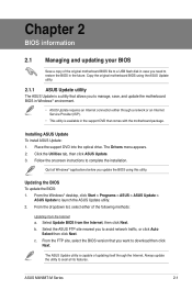
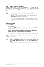
... manage, save, and update the motherboard BIOS in Windows® environment. • ASUS Update requires an Internet connection either of the following methods: Updating from the Internet, then click Next. ASUS M4N68T-M Series 2-1 Copy the original motherboard BIOS using this utility. Always update the utility... to avail all Windows® applications before you to restore the BIOS in the support DVD that you need to avoid...
... manage, save, and update the motherboard BIOS in Windows® environment. • ASUS Update requires an Internet connection either of the following methods: Updating from the Internet, then click Next. ASUS M4N68T-M Series 2-1 Copy the original motherboard BIOS using this utility. Always update the utility... to avail all Windows® applications before you to restore the BIOS in the support DVD that you need to avoid...
User Manual
Page 40
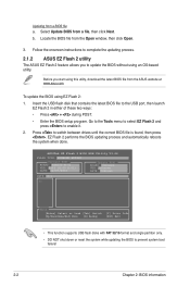
... to enable it. 2. Before you to complete the updating process. 2.1.2 ASUS EZ Flash 2 utility The ASUS EZ Flash 2 feature allows you start using EZ Flash 2: 1. ASUSTek EZ Flash 2 BIOS ROM Utility V3.44 FLASH TYPE: WINBOND W25X80 Current ROM BOARD: M4N68T-M-V2 VER: 0303 (H:00 B:01) DATE: xx/07/2010 Update ROM BOARD: Unknown VER...
... to enable it. 2. Before you to complete the updating process. 2.1.2 ASUS EZ Flash 2 utility The ASUS EZ Flash 2 feature allows you start using EZ Flash 2: 1. ASUSTek EZ Flash 2 BIOS ROM Utility V3.44 FLASH TYPE: WINBOND W25X80 Current ROM BOARD: M4N68T-M-V2 VER: 0303 (H:00 B:01) DATE: xx/07/2010 Update ROM BOARD: Unknown VER...
User Manual
Page 41
... using the motherboard support DVD or a removable device that contains the BIOS file to the USB port or to section 2.8 Exit menu for the BIOS file. Ensure to load the BIOS default settings to restore the BIOS file when it on the system. 2. ASUS M4N68T-M Series 2-3 You can cause system boot failure! For motherboards without a floppy...
... using the motherboard support DVD or a removable device that contains the BIOS file to the USB port or to section 2.8 Exit menu for the BIOS file. Ensure to load the BIOS default settings to restore the BIOS file when it on the system. 2. ASUS M4N68T-M Series 2-3 You can cause system boot failure! For motherboards without a floppy...
User Manual
Page 42
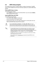
... program to update the BIOS or configure its routines. Entering BIOS Setup at startup To enter BIOS Setup at www.asus.com to download the latest BIOS file for this motherboard. 2-4 Chapter 2: BIOS information If the system becomes unstable after POST: • Press ++ simultaneously. • Press the reset button on the system chassis. • Press the...
... program to update the BIOS or configure its routines. Entering BIOS Setup at startup To enter BIOS Setup at www.asus.com to download the latest BIOS file for this motherboard. 2-4 Chapter 2: BIOS information If the system becomes unstable after POST: • Press ++ simultaneously. • Press the reset button on the system chassis. • Press the...

User Manual
Page 43
...configuration Boot For changing the system boot configuration Tools For configuring options for that particular menu. 2.2.1 BIOS menu screen Menu items Menu bar Configuration fields Main Advanced M4N68T-M-V2 BIOS Setup Power Boot Tools Exit Main Settings System Time [22:03:55] System Date [Mon 01...TAB] or [SHIFT-TAB] to select items in the menu and change the settings. Use the navigation keys to select a field. ASUS M4N68T-M Series 2-5 Change Field Tab Select Field F1 General Help F10 Save and Exit ESC Exit v02.61 (C)Copyright 1985-2009, American Megatrends...
...configuration Boot For changing the system boot configuration Tools For configuring options for that particular menu. 2.2.1 BIOS menu screen Menu items Menu bar Configuration fields Main Advanced M4N68T-M-V2 BIOS Setup Power Boot Tools Exit Main Settings System Time [22:03:55] System Date [Mon 01...TAB] or [SHIFT-TAB] to select items in the menu and change the settings. Use the navigation keys to select a field. ASUS M4N68T-M Series 2-5 Change Field Tab Select Field F1 General Help F10 Save and Exit ESC Exit v02.61 (C)Copyright 1985-2009, American Megatrends...
User Manual
Page 44
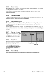
... +- A configurable field is enclosed in brackets, and is highlighted when selected. To change the value of the selected item. 2-6 Chapter 2: BIOS information Press the / arrow keys or / keys to RSDT pointer list. 2.2.8 Scroll bar A scroll bar appears on the right side of options... 2.2.5 Submenu items A solid triangle before each item on a menu screen means that is not user-configurable. Pop-up window Main Advanced M4N68T-M-V2 UTILITY Power Boot Tools Exit Select a menu item then press Suspend Mode ACPI 2.0 Support ACPI APIC support to display a list of ...
... +- A configurable field is enclosed in brackets, and is highlighted when selected. To change the value of the selected item. 2-6 Chapter 2: BIOS information Press the / arrow keys or / keys to RSDT pointer list. 2.2.8 Scroll bar A scroll bar appears on the right side of options... 2.2.5 Submenu items A solid triangle before each item on a menu screen means that is not user-configurable. Pop-up window Main Advanced M4N68T-M-V2 UTILITY Power Boot Tools Exit Select a menu item then press Suspend Mode ACPI 2.0 Support ACPI APIC support to display a list of ...
User Manual
Page 45
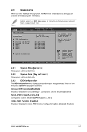
Main Advanced Main Settings M4N68T-M-V2 BIOS Setup Power Boot Tools Exit System Time [22:03:55] System Date [Mon 01/07/2002] IDE Configuration Primary IDE Master Primary IDE Slave SATA1 ... onboard IDE port. Select an item then press to navigate through them. Refer to section 2.2.1 BIOS menu screen for information on the menu screen items and how to display the submenu. Configuration options: [Disabled] [Enabled] ASUS M4N68T-M Series 2-7 Change Field Tab Select Field F1 General Help F10 Save and Exit ESC Exit v02...
Main Advanced Main Settings M4N68T-M-V2 BIOS Setup Power Boot Tools Exit System Time [22:03:55] System Date [Mon 01/07/2002] IDE Configuration Primary IDE Master Primary IDE Slave SATA1 ... onboard IDE port. Select an item then press to navigate through them. Refer to section 2.2.1 BIOS menu screen for information on the menu screen items and how to display the submenu. Configuration options: [Disabled] [Enabled] ASUS M4N68T-M Series 2-7 Change Field Tab Select Field F1 General Help F10 Save and Exit ESC Exit v02...


