
User Manual
Page 3
Contents Notices...vi Safety information vii About this guide vii M4N68T V2 Series specifications summary ix Chapter 1: Product introduction 1.1 Welcome 1-1 1.2 Package contents 1-1 1.3 Special features 1-1 1.3.1 Product highlights 1-1 1.3.2 Innovative ASUS features 1-3 1.4 Before you proceed 1-4 1.5 Motherboard overview 1-5 1.5.1 Placement direction 1-5 1.5.2 Screw holes 1-5 1.5.3 Motherboard layout 1-6 1.5.4 Layout contents 1-7 1.6 Central Processing Unit (CPU 1-7 1.6.1 Installing the CPU 1-7 1.6.2 Installing the heatsink and ...
Contents Notices...vi Safety information vii About this guide vii M4N68T V2 Series specifications summary ix Chapter 1: Product introduction 1.1 Welcome 1-1 1.2 Package contents 1-1 1.3 Special features 1-1 1.3.1 Product highlights 1-1 1.3.2 Innovative ASUS features 1-3 1.4 Before you proceed 1-4 1.5 Motherboard overview 1-5 1.5.1 Placement direction 1-5 1.5.2 Screw holes 1-5 1.5.3 Motherboard layout 1-6 1.5.4 Layout contents 1-7 1.6 Central Processing Unit (CPU 1-7 1.6.1 Installing the CPU 1-7 1.6.2 Installing the heatsink and ...

User Manual
Page 9
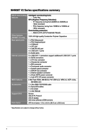
...and 200 series CPUs support up to DDR3 1066MHz. Supports S/PDIF Out interface at the back panel) Core Unlocker ASUS EPU-4 Engine ASUS CrashFree BIOS 3 ASUS EZ Flash 2 ASUS Q-Fan ASUS AI NET 2 ASUS MyLogo 2 (continued on the next page) ix We recommend a maximum of 4GB or more, Windows® 32... output. 10 x USB 2.0/1.1 ports (6 ports at the mid-board, 4 ports at the mid-board - M4N68T V2 Series specifications summary CPU Chipset System bus Memory Expansion slots Storage LAN Audio USB ASUS unique features AMD® Socket AM3 for AMD® Phenom™ II x6 / Phenom™ II / ...
...and 200 series CPUs support up to DDR3 1066MHz. Supports S/PDIF Out interface at the back panel) Core Unlocker ASUS EPU-4 Engine ASUS CrashFree BIOS 3 ASUS EZ Flash 2 ASUS Q-Fan ASUS AI NET 2 ASUS MyLogo 2 (continued on the next page) ix We recommend a maximum of 4GB or more, Windows® 32... output. 10 x USB 2.0/1.1 ports (6 ports at the mid-board, 4 ports at the mid-board - M4N68T V2 Series specifications summary CPU Chipset System bus Memory Expansion slots Storage LAN Audio USB ASUS unique features AMD® Socket AM3 for AMD® Phenom™ II x6 / Phenom™ II / ...
User Manual
Page 10
M4N68T V2 Series specifications summary ASUS overclocking features Other features (M4N68T V2 only) Rear panel ports Internal connectors BIOS features Accessories Support DVD Form factor Intelligent overclocking tools: - PCIe frequency tuning from 200MHz to 300MHz at 1MHz increment Overclocking protection: - ASUS C.P.R. (CPU Parameter Recall) 100% All High-quality Conductive Polymer Capacitors 1 x PS/2 Mouse port 1 x PS/2 Keyboard port...
M4N68T V2 Series specifications summary ASUS overclocking features Other features (M4N68T V2 only) Rear panel ports Internal connectors BIOS features Accessories Support DVD Form factor Intelligent overclocking tools: - PCIe frequency tuning from 200MHz to 300MHz at 1MHz increment Overclocking protection: - ASUS C.P.R. (CPU Parameter Recall) 100% All High-quality Conductive Polymer Capacitors 1 x PS/2 Mouse port 1 x PS/2 Keyboard port...

User Manual
Page 11
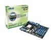
Before you for the following items. Motherboard Cables Accessories Application DVD Documentation ASUS M4N68T V2 Series motherboard 2 x Serial ATA cables 1 x Ultra DMA 133/100/66 cable 1 x I/O shield ASUS motherboard Support DVD User Manual • M4N68T V2 Series motherboards include M4N68T V2 and M4N68T LE V2 two models. Chapter 1 Product introduction 1.1 Welcome! M4N68T V2 Series motherboards are ready to support the upcoming six-core AMD...
Before you for the following items. Motherboard Cables Accessories Application DVD Documentation ASUS M4N68T V2 Series motherboard 2 x Serial ATA cables 1 x Ultra DMA 133/100/66 cable 1 x I/O shield ASUS motherboard Support DVD User Manual • M4N68T V2 Series motherboards include M4N68T V2 and M4N68T LE V2 two models. Chapter 1 Product introduction 1.1 Welcome! M4N68T V2 Series motherboards are ready to support the upcoming six-core AMD...

User Manual
Page 12
.../s technology and RAID support This motherboard supports hard drives based on the headphone while playing multichannel network games. 100% All High-quality Conductive Polymer Capacitors (M4N68T V2 only) This motherboard uses all high-quality conductive polymer capacitors for high-speed data retrieval and save. Dual-Channel DDR3 1800 (O.C.) support This motherboard supports...
.../s technology and RAID support This motherboard supports hard drives based on the headphone while playing multichannel network games. 100% All High-quality Conductive Polymer Capacitors (M4N68T V2 only) This motherboard uses all high-quality conductive polymer capacitors for high-speed data retrieval and save. Dual-Channel DDR3 1800 (O.C.) support This motherboard supports...

User Manual
Page 13
... performance boost by simply unlocking the extra cores, without interrupting ongoing work or games, simply through pressing the button. ASUS M4N68T V2 Series 1-3 ASUS Turbo Key ASUS Turbo Key allows you to turn on the system and any faulty cable connections are reported back up to personalize your...the bundled support DVD or a USB flash disk that detects the current system loadings and adjusts the power consumption in real time. ASUS Q-Fan ASUS Q-Fan technology intelligently adjusts the CPU fan speed according to system loading to ensure a quiet, cool, and efficient operation. After...
... performance boost by simply unlocking the extra cores, without interrupting ongoing work or games, simply through pressing the button. ASUS M4N68T V2 Series 1-3 ASUS Turbo Key ASUS Turbo Key allows you to turn on the system and any faulty cable connections are reported back up to personalize your...the bundled support DVD or a USB flash disk that detects the current system loadings and adjusts the power consumption in real time. ASUS Q-Fan ASUS Q-Fan technology intelligently adjusts the CPU fan speed according to system loading to ensure a quiet, cool, and efficient operation. After...

User Manual
Page 14
... BIOS C.P.R. feature automatically restores the CPU default settings when the system hangs due to open the system chassis and clear the RTC data. Green ASUS This motherboard and its packaging comply with the European Union's Restriction on a grounded antistatic pad or in the bag that came with the... may cause severe damage to safeguard consumers' health while minimizing the impact on the environment. 1.4 Before you proceed Take note of the onboard LED. M4N68T V2 Series SB_PWR ON OFF Standby Power Powered Off M4N68T V2 Series Onboard LED 1-4 Chapter 1: Product introduction
... BIOS C.P.R. feature automatically restores the CPU default settings when the system hangs due to open the system chassis and clear the RTC data. Green ASUS This motherboard and its packaging comply with the European Union's Restriction on a grounded antistatic pad or in the bag that came with the... may cause severe damage to safeguard consumers' health while minimizing the impact on the environment. 1.4 Before you proceed Take note of the onboard LED. M4N68T V2 Series SB_PWR ON OFF Standby Power Powered Off M4N68T V2 Series Onboard LED 1-4 Chapter 1: Product introduction

User Manual
Page 15
The edge with external ports goes to the chassis. Place this side towards the rear of the chassis as indicated in the correct orientation. DO NOT overtighten the screws! M4N68T V2 Series ASUS M4N68T V2 Series 1-5 1.5 Motherboard overview 1.5.1 Placement direction When installing the motherboard, ensure that you place it into the chassis in the image below. 1.5.2 Screw holes Place six screws into the holes indicated by circles to secure the motherboard to the rear part of the chassis. Doing so can damage the motherboard.
The edge with external ports goes to the chassis. Place this side towards the rear of the chassis as indicated in the correct orientation. DO NOT overtighten the screws! M4N68T V2 Series ASUS M4N68T V2 Series 1-5 1.5 Motherboard overview 1.5.1 Placement direction When installing the motherboard, ensure that you place it into the chassis in the image below. 1.5.2 Screw holes Place six screws into the holes indicated by circles to secure the motherboard to the rear part of the chassis. Doing so can damage the motherboard.

User Manual
Page 17
...) 1-17 2. Locate the CPU socket on the motherboard. System panel connector (10-1 pin F_PANEL) 1-24 ATX12V) 4. Digital audio connector (4-1 pin SPDIF_OUT) 1-25 6. M4N68T V2 Series M4N68T V2 Series CPU socket AM3 ASUS M4N68T V2 Series 1-7 USB device wake-up (3-pin USBPW1-4, USBPW5-10) 1-18 10. ATX power connectors (24-pin EATXPWR, 4-pin 1-21 11. AMD CPU socket...
...) 1-17 2. Locate the CPU socket on the motherboard. System panel connector (10-1 pin F_PANEL) 1-24 ATX12V) 4. Digital audio connector (4-1 pin SPDIF_OUT) 1-25 6. M4N68T V2 Series M4N68T V2 Series CPU socket AM3 ASUS M4N68T V2 Series 1-7 USB device wake-up (3-pin USBPW1-4, USBPW5-10) 1-18 10. ATX power connectors (24-pin EATXPWR, 4-pin 1-21 11. AMD CPU socket...

User Manual
Page 18
... secure the CPU. Hardware monitoring errors can also refer to unlock the socket, then lift it fits in completely. 3. M4N68T V2 Series CPU_FAN CPU FAN PWM CPU FAN IN CPU FAN PWR GND M4N68T V2 Series CPU fan connector DO NOT forget to indicate that the CPU corner with the gold triangle matches the...
... secure the CPU. Hardware monitoring errors can also refer to unlock the socket, then lift it fits in completely. 3. M4N68T V2 Series CPU_FAN CPU FAN PWM CPU FAN IN CPU FAN PWR GND M4N68T V2 Series CPU fan connector DO NOT forget to indicate that the CPU corner with the gold triangle matches the...

User Manual
Page 19
Place the heatsink on top of the retention bracket to the retention module base. 1 2 3 4 5 ASUS M4N68T V2 Series 1-9 Attach one end of the installed CPU, ensuring that the heatsink fits properly on the retention module base. • The retention module base is ...
Place the heatsink on top of the retention bracket to the retention module base. 1 2 3 4 5 ASUS M4N68T V2 Series 1-9 Attach one end of the installed CPU, ensuring that the heatsink fits properly on the retention module base. • The retention module base is ...

User Manual
Page 20
... the heatsink and fan to connect the CPU fan connector! Align the other end of the DDR3 DIMM sockets: DIMM_A2 DIMM_B2 DIMM_A1 DIMM_B1 M4N68T V2 Series Channel Channel A Channel B M4N68T V2 Series 240-pin DDR3 DIMM sockets Sockets DIMM_A1 and DIMM_A2 DIMM_B1 and DIMM_B2 1-10 Chapter 1: Product introduction DO NOT forget to the module...
... the heatsink and fan to connect the CPU fan connector! Align the other end of the DDR3 DIMM sockets: DIMM_A2 DIMM_B2 DIMM_A1 DIMM_B1 M4N68T V2 Series Channel Channel A Channel B M4N68T V2 Series 240-pin DDR3 DIMM sockets Sockets DIMM_A1 and DIMM_A2 DIMM_B1 and DIMM_B2 1-10 Chapter 1: Product introduction DO NOT forget to the module...

User Manual
Page 21
...memory modules from the higher-sized channel is then mapped for the dual-channel configuration. With ASUS design, this motherboard can be about 3GB or less. M4N68T V2 series Motherboards Qualified Vendors Lists (QVL) DDR3-1800(O.C.) MHz capability Vendor Part No. Size... N/A Heat-Sink Package CL N/A 8-8-8-24 9-9-9-27 8-8-8-24 DIMM support A* B* C* • • • • • • • ASUS M4N68T V2 Series 1-11 1.7.2 Memory configurations You may install 512MB, 1GB, 2GB, and 4GB unbuffered non-ECC DDR3 DIMMs into the DIMM sockets. • You may not...
...memory modules from the higher-sized channel is then mapped for the dual-channel configuration. With ASUS design, this motherboard can be about 3GB or less. M4N68T V2 series Motherboards Qualified Vendors Lists (QVL) DDR3-1800(O.C.) MHz capability Vendor Part No. Size... N/A Heat-Sink Package CL N/A 8-8-8-24 9-9-9-27 8-8-8-24 DIMM support A* B* C* • • • • • • • ASUS M4N68T V2 Series 1-11 1.7.2 Memory configurations You may install 512MB, 1GB, 2GB, and 4GB unbuffered non-ECC DDR3 DIMMs into the DIMM sockets. • You may not...

User Manual
Page 23
... Package Heat-Sink Package N/A N/A 7-7-7-18 9-9-9-24 9 7-7-7-24 9 9 9 N/A N/A 9 9 7-7-7-20 N/A N/A N/A N/A N/A N/A N/A N/A N/A N/A N/A 8-8-8-24 N/A N/A N/A N/A N/A 9 N/A 7-7-7-20 8-8-8-24 DIMM support A* B* C • •• • •• • •• • •• ASUS M4N68T V2 Series 1-13 DDR3-1333MHz capability Vendor Part No. Size SS/ Chip DS Brand Chip NO.
... Package Heat-Sink Package N/A N/A 7-7-7-18 9-9-9-24 9 7-7-7-24 9 9 9 N/A N/A 9 9 7-7-7-20 N/A N/A N/A N/A N/A N/A N/A N/A N/A N/A N/A 8-8-8-24 N/A N/A N/A N/A N/A 9 N/A 7-7-7-20 8-8-8-24 DIMM support A* B* C • •• • •• • •• • •• ASUS M4N68T V2 Series 1-13 DDR3-1333MHz capability Vendor Part No. Size SS/ Chip DS Brand Chip NO.

User Manual
Page 25
Remove the DIMM from the socket. DIMM notch ASUS M4N68T V2 Series 1-15 Firmly insert the DIMM into a socket in the wrong direction to unlock a DIMM socket. 2. Locked Retaining Clip 1.7.4 Removing a DIMM To remove a DIMM: 1. The ...
Remove the DIMM from the socket. DIMM notch ASUS M4N68T V2 Series 1-15 Firmly insert the DIMM into a socket in the wrong direction to unlock a DIMM socket. 2. Locked Retaining Clip 1.7.4 Removing a DIMM To remove a DIMM: 1. The ...

User Manual
Page 27
... 12 23 Normal (Default) Clear RTC M4N68T V2 Series Clear RTC RAM To erase the RTC RAM: 1. You can automatically reset parameter settings to pins 1-2. 3. For system failure due to pins 2-3. Move the ... clear the RTC when the system hangs due to reenter data. Shut down the key during the boot process and enter BIOS setup to overclocking. ASUS M4N68T V2 Series 1-17 Keep the cap on CLRTC jumper default position. Turn OFF the computer and unplug the power cord. 2. Except when clearing the RTC RAM...
... 12 23 Normal (Default) Clear RTC M4N68T V2 Series Clear RTC RAM To erase the RTC RAM: 1. You can automatically reset parameter settings to pins 1-2. 3. For system failure due to pins 2-3. Move the ... clear the RTC when the system hangs due to reenter data. Shut down the key during the boot process and enter BIOS setup to overclocking. ASUS M4N68T V2 Series 1-17 Keep the cap on CLRTC jumper default position. Turn OFF the computer and unplug the power cord. 2. Except when clearing the RTC RAM...

User Manual
Page 28
... DRAM in slow refresh, power supply in low power mode) using the connected USB devices. KBPWR 12 23 +5V +5VSB (Default) M4N68T V2 Series M4N68T V2 Series Keyboard power setting 1-18 Chapter 1: Product introduction This feature requires an ATX power supply that can wake up the computer from S3 ...(3-pin KBPWR) This jumper allows you can supply at least 1A on the keyboard. USBPW1-4 12 23 M4N68T V2 Series +5V +5VSB (Default) USBPW5-10 12 23 +5V +5VSB (Default) M4N68T V2 Series USB device wake-up the compurer from S1 sleep mode (CPU stopped, DRAM refreshed, system running...
... DRAM in slow refresh, power supply in low power mode) using the connected USB devices. KBPWR 12 23 +5V +5VSB (Default) M4N68T V2 Series M4N68T V2 Series Keyboard power setting 1-18 Chapter 1: Product introduction This feature requires an ATX power supply that can wake up the computer from S3 ...(3-pin KBPWR) This jumper allows you can supply at least 1A on the keyboard. USBPW1-4 12 23 M4N68T V2 Series +5V +5VSB (Default) USBPW5-10 12 23 +5V +5VSB (Default) M4N68T V2 Series USB device wake-up the compurer from S1 sleep mode (CPU stopped, DRAM refreshed, system running...

User Manual
Page 29
... Speed LED Status OFF ORANGE GREEN Description 10Mbps connection 100Mbps connection 1Gbps connection ACT/LINK SPEED LED LED LAN port 4. This port connects to a microphone. ASUS M4N68T V2 Series 1-19 Microphone port (pink). This 25-pin port connects a parallel printer, a scanner, or other audio sources. 5. LAN (RJ-45) port. This port connects to...
... Speed LED Status OFF ORANGE GREEN Description 10Mbps connection 100Mbps connection 1Gbps connection ACT/LINK SPEED LED LED LAN port 4. This port connects to a microphone. ASUS M4N68T V2 Series 1-19 Microphone port (pink). This 25-pin port connects a parallel printer, a scanner, or other audio sources. 5. LAN (RJ-45) port. This port connects to...

User Manual
Page 30
... AAFP PIN 1 PIN 1 MIC2 MICPWR Line out_R NC Line out_L PORT1 L PORT1 R PORT2 R SENSE_SEND PORT2 L HD-audio-compliant Legacy AC'97 pin definition compliant definition M4N68T V2 Series Front panel audio connector • We recommend that supports either High Definition Audio or AC`97 audio standard. See section 2.4.3 Chipset for details. •...
... AAFP PIN 1 PIN 1 MIC2 MICPWR Line out_R NC Line out_L PORT1 L PORT1 R PORT2 R SENSE_SEND PORT2 L HD-audio-compliant Legacy AC'97 pin definition compliant definition M4N68T V2 Series Front panel audio connector • We recommend that supports either High Definition Audio or AC`97 audio standard. See section 2.4.3 Chipset for details. •...

User Manual
Page 31
.../PSCalculator.aspx?SLanguage=en-us for your system, refer to use a PSU with a minimum of 300W. ATX12V EATXPWR +12V DC +12V DC M4N68T V2 Series GND GND +3 Volts +12 Volts +12 Volts +5V Standby Power OK PIN 1 GND +5 Volts GND +5 Volts GND +3 Volts +3 Volts PIN... system may become unstable or may not boot up . • We recommend that you are uncertain about the minimum power supply requirement for details. ASUS M4N68T V2 Series 1-21 Otherwise, the system will not boot up if the power is inadequate. • If you use a PSU with higher power output ...
.../PSCalculator.aspx?SLanguage=en-us for your system, refer to use a PSU with a minimum of 300W. ATX12V EATXPWR +12V DC +12V DC M4N68T V2 Series GND GND +3 Volts +12 Volts +12 Volts +5V Standby Power OK PIN 1 GND +5 Volts GND +5 Volts GND +3 Volts +3 Volts PIN... system may become unstable or may not boot up . • We recommend that you are uncertain about the minimum power supply requirement for details. ASUS M4N68T V2 Series 1-21 Otherwise, the system will not boot up if the power is inadequate. • If you use a PSU with higher power output ...


