
User Guide
Page 4
... time 3-1 3.2 Powering off the computer 3-2 3.2.1 Using the OS shut down function 3-2 3.2.2 Using the dual function power switch 3-2 Chapter 4: BIOS setup 4.1 Managing and updating your BIOS 4-1 4.1.1 Creating a bootable floppy disk 4-1 4.1.2 AFUDOS utility 4-2 4.1.3 ASUS CrashFree BIOS 2 utility 4-4 4.2 BIOS setup program 4-5 4.2.1 BIOS menu screen 4-6 4.2.2 Menu bar 4-6 4.2.3 Navigation keys 4-6 4.2.4 Menu items 4-7 4.2.5 Sub-menu items 4-7 4.2.6 Configuration fields...
... time 3-1 3.2 Powering off the computer 3-2 3.2.1 Using the OS shut down function 3-2 3.2.2 Using the dual function power switch 3-2 Chapter 4: BIOS setup 4.1 Managing and updating your BIOS 4-1 4.1.1 Creating a bootable floppy disk 4-1 4.1.2 AFUDOS utility 4-2 4.1.3 ASUS CrashFree BIOS 2 utility 4-4 4.2 BIOS setup program 4-5 4.2.1 BIOS menu screen 4-6 4.2.2 Menu bar 4-6 4.2.3 Navigation keys 4-6 4.2.4 Menu items 4-7 4.2.5 Sub-menu items 4-7 4.2.6 Configuration fields...
User Guide
Page 5
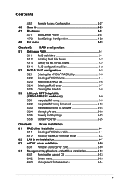
... a RAID Volume 5-4 5.2.3 Rebuilding a RAID set 5-6 5.2.4 Deleting a RAID array 5-7 5.2.5 Clearing the disk data 5-8 5.3 LSI Logic MPT Setup Utility (KFSN4-DRE/SAS model only 5-9 5.3.1 Integrated Mirroring 5-9 5.3.2 Integrated Mirroring Enhanced 5-13 5.3.3 Integrated Striping (IS) volume 5-15 5.3.4 Managing Arrays 5-18 5.3.5 Viewing SAS topology 5-23 5.5.6 Global Properties 5-25 Chapter 6: Driver installation 6.1 RAID driver installation 6-1 6.1.1 Creating a RAID driver disk 6-1 6.1.2 Installing the...
... a RAID Volume 5-4 5.2.3 Rebuilding a RAID set 5-6 5.2.4 Deleting a RAID array 5-7 5.2.5 Clearing the disk data 5-8 5.3 LSI Logic MPT Setup Utility (KFSN4-DRE/SAS model only 5-9 5.3.1 Integrated Mirroring 5-9 5.3.2 Integrated Mirroring Enhanced 5-13 5.3.3 Integrated Striping (IS) volume 5-15 5.3.4 Managing Arrays 5-18 5.3.5 Viewing SAS topology 5-23 5.5.6 Global Properties 5-25 Chapter 6: Driver installation 6.1 RAID driver installation 6-1 6.1.1 Creating a RAID driver disk 6-1 6.1.2 Installing the...

User Guide
Page 12
KFSN4-DRE Series specifications summary Onboard I/O Connectors Rear I/O Connectors Management Solution Monitoring EMI Environment Floppy Connector PSU Connector Management Connector USB Connectors Fan Header SMBus Chassis Intruder Front LAN LED Serial Port Header External Serial Port External USB Port VGA Port RJ-45 PS/2 KB/Mouse Software Out of Band Remote Management CPU Temperature FAN RPM...
KFSN4-DRE Series specifications summary Onboard I/O Connectors Rear I/O Connectors Management Solution Monitoring EMI Environment Floppy Connector PSU Connector Management Connector USB Connectors Fan Header SMBus Chassis Intruder Front LAN LED Serial Port Header External Serial Port External USB Port VGA Port RJ-45 PS/2 KB/Mouse Software Out of Band Remote Management CPU Temperature FAN RPM...
User Guide
Page 38
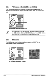
... comes with the PCI Express specifications. The KFSN4-DRE/SAS comes with one PCIE x 16 slot (x 8link); the KFSN4-DRE comes with one PCIE x 16 slot (x 16link). 2.5.5 BMC socket The BMC socket socket on the motherboard supports an ASUS® Server Management Board 3 Series (ASMB3). ® KFSN4-DRE Series BMC SOCKET 2-18 Chapter 2: Hardware information ® 2.5.4 PCI Express x16...
... comes with the PCI Express specifications. The KFSN4-DRE/SAS comes with one PCIE x 16 slot (x 8link); the KFSN4-DRE comes with one PCIE x 16 slot (x 16link). 2.5.5 BMC socket The BMC socket socket on the motherboard supports an ASUS® Server Management Board 3 Series (ASMB3). ® KFSN4-DRE Series BMC SOCKET 2-18 Chapter 2: Hardware information ® 2.5.4 PCI Express x16...

User Guide
Page 43
This RJ-45 port functions only when you install ASMB3/iKVM management card. 3. This port allows Gigabit connection to the table below for a VGA monitor or other serial devices. 6. Refer to a Local Area Network (LAN) ... BLINKING Data activity Speed LED Status Description OFF 10 Mbps connection ORANGE 100 Mbps connection GREEN 1 Gbps connection ACT/LINK SPEED LED LED LAN port ASUS KFSN4-DRE Series 2-23 2.7 Connectors 2.7.1 Rear panel connectors 1 2 3 4 5 6 7 8 1. This port is for the LAN port LED indications. Video Graphics Adapter port. This port is ...
This RJ-45 port functions only when you install ASMB3/iKVM management card. 3. This port allows Gigabit connection to the table below for a VGA monitor or other serial devices. 6. Refer to a Local Area Network (LAN) ... BLINKING Data activity Speed LED Status Description OFF 10 Mbps connection ORANGE 100 Mbps connection GREEN 1 Gbps connection ACT/LINK SPEED LED LED LAN port ASUS KFSN4-DRE Series 2-23 2.7 Connectors 2.7.1 Rear panel connectors 1 2 3 4 5 6 7 8 1. This port is for the LAN port LED indications. Video Graphics Adapter port. This port is ...

User Guide
Page 48
... power required by your system. Power Supply SMBus connector (5-pin PSUSMB1) This connector allows you to connect SMBus (System Management Bus) to the power supply unit to fit these connectors in only one orientation. Find the proper orientation and push down... PSON# Ground Ground Ground -5 Volts +5 Volts +5 Volts +5 Volts Ground 12V1 12V1 12V2 12V2 KFSN4-DRE Series ATX power connectors 9. PSUSMB1 I2C_7_CLK# I2C_7_DATA# NC GND +3.3V Remote Sense ® KFSN4-DRE Series Power supply SMBus connector 2-28 Chapter 2: Hardware information Devices communicate with more power-consuming devices...
... power required by your system. Power Supply SMBus connector (5-pin PSUSMB1) This connector allows you to connect SMBus (System Management Bus) to the power supply unit to fit these connectors in only one orientation. Find the proper orientation and push down... PSON# Ground Ground Ground -5 Volts +5 Volts +5 Volts +5 Volts Ground 12V1 12V1 12V2 12V2 KFSN4-DRE Series ATX power connectors 9. PSUSMB1 I2C_7_CLK# I2C_7_DATA# NC GND +3.3V Remote Sense ® KFSN4-DRE Series Power supply SMBus connector 2-28 Chapter 2: Hardware information Devices communicate with more power-consuming devices...

User Guide
Page 51
...2 cable to this connector. Locator Button/Switch (2-pin LOCATORBTN) This connector is always lit when linked. 3. ASUS KFSN4-DRE Series 2-31 13. LOCATORBTN# GND LOCATORLED2LOCATORLED2+ KFSN4-DRE Series Auxiliary panel connector 3 454 1. LAN2 link activity LED (2-pin LAN2_LINKACTLED) This 2-pin connector is for the... Connect the LAN2 Activity LED cable to this lead to the system front panel. When you to connect SMBus (System Management Bus) devices to record a chassis intrusion event. 5. Devices communicate with an intrusion detection feature. LAN1 link activity LED ...
...2 cable to this connector. Locator Button/Switch (2-pin LOCATORBTN) This connector is always lit when linked. 3. ASUS KFSN4-DRE Series 2-31 13. LOCATORBTN# GND LOCATORLED2LOCATORLED2+ KFSN4-DRE Series Auxiliary panel connector 3 454 1. LAN2 link activity LED (2-pin LAN2_LINKACTLED) This 2-pin connector is for the... Connect the LAN2 Activity LED cable to this lead to the system front panel. When you to connect SMBus (System Management Bus) devices to record a chassis intrusion event. 5. Devices communicate with an intrusion detection feature. LAN1 link activity LED ...

User Guide
Page 58
Chapter summary 4 4.1 Managing and updating your BIOS 4-1 4.2 BIOS setup program 4-5 4.3 Main menu 4-8 4.4 Advanced menu 4-13 4.5 Server menu 4-27 4.6 Security menu 4-29 4.7 Boot menu 4-31 4.8 Exit menu 4-33 ASUS KFSN4-DRE Series
Chapter summary 4 4.1 Managing and updating your BIOS 4-1 4.2 BIOS setup program 4-5 4.3 Main menu 4-8 4.4 Advanced menu 4-13 4.5 Server menu 4-27 4.6 Security menu 4-29 4.7 Boot menu 4-31 4.8 Exit menu 4-33 ASUS KFSN4-DRE Series

User Guide
Page 59
...1.44MB floppy disk into the drive. Click File from the menu, then select Format. ASUS CrashFree BIOS 2 (Updates the BIOS using the ASUS Update or AFUDOS utilities. 4.1.1 Creating a bootable floppy disk 1. ASUS KFSN4-DRE Series 4-1 c. A Format 3½ Floppy Disk window appears. b. At the DOS ...instructions to the floppy disk drive. 4.1 Managing and updating your optical drive. Insert a 1.44 MB floppy disk to continue. 2. Windows® 2000 environment To create a set of the following utilities allow you need to manage and update the motherboard Basic Input/Output System...
...1.44MB floppy disk into the drive. Click File from the menu, then select Format. ASUS CrashFree BIOS 2 (Updates the BIOS using the ASUS Update or AFUDOS utilities. 4.1.1 Creating a bootable floppy disk 1. ASUS KFSN4-DRE Series 4-1 c. A Format 3½ Floppy Disk window appears. b. At the DOS ...instructions to the floppy disk drive. 4.1 Managing and updating your optical drive. Insert a 1.44 MB floppy disk to continue. 2. Windows® 2000 environment To create a set of the following utilities allow you need to manage and update the motherboard Basic Input/Output System...

User Guide
Page 63
.... This requires you to use as easy to make it lets you can update using the provided utility described in section 4.1 Managing and updating your system, or prompted to ensure system compatibility and stability. otherwise, POST continues with the opportunity to enter the ... The SPI chip on the system chassis. If you can enable the security password feature or change the configuration of the SPI chip. ASUS KFSN4-DRE Series 4-5 Use the BIOS Setup program when you with its test routines. 4.2 BIOS setup program This motherboard supports a programmable Serial Peripheral...
.... This requires you to use as easy to make it lets you can update using the provided utility described in section 4.1 Managing and updating your system, or prompted to ensure system compatibility and stability. otherwise, POST continues with the opportunity to enter the ... The SPI chip on the system chassis. If you can enable the security password feature or change the configuration of the SPI chip. ASUS KFSN4-DRE Series 4-5 Use the BIOS Setup program when you with its test routines. 4.2 BIOS setup program This motherboard supports a programmable Serial Peripheral...

User Guide
Page 82
... APM Configuration Options Restore On AC Power Loss Resume by Ring Resume by PCIE Wake# Resume by RTC [Disabled] Allows you to change Advanced Power Management (APM) features. Configuration options: [Disabled] [Enabled] Resume by RTC [Last State] [Disabled] [Disabled] [Disabled] Power Off Power On Last State →← Select Screen ↑...
... APM Configuration Options Restore On AC Power Loss Resume by Ring Resume by PCIE Wake# Resume by RTC [Disabled] Allows you to change Advanced Power Management (APM) features. Configuration options: [Disabled] [Enabled] Resume by RTC [Last State] [Disabled] [Disabled] [Disabled] Power Off Power On Last State →← Select Screen ↑...

User Guide
Page 95
...disk array management software directs all applications to the selected hard disk drive. Use two new drives or use three or more hard disk drives for this setup. KFSN4-DRE/2S model ... rate, double that allows you to configure RAID 0 and RAID 1 with SATA hard disk drives. ASUS KFSN4-DRE Series 5-1 The new drive must be of two new identical hard disk drives is required for this ...stored on a different disk. Use of the same size or larger than the existing drive. KFSN4-DRE/SAS model • The NVIDIA® nForce Professional 2200 chipset comes with a built-in SATA RAID...
...disk array management software directs all applications to the selected hard disk drive. Use two new drives or use three or more hard disk drives for this setup. KFSN4-DRE/2S model ... rate, double that allows you to configure RAID 0 and RAID 1 with SATA hard disk drives. ASUS KFSN4-DRE Series 5-1 The new drive must be of two new identical hard disk drives is required for this ...stored on a different disk. Use of the same size or larger than the existing drive. KFSN4-DRE/SAS model • The NVIDIA® nForce Professional 2200 chipset comes with a built-in SATA RAID...

User Guide
Page 112
... Boot Order Boot Support SAS1064E 00 04:00:00 1.22.01.00-IR 500E0101:23456712 2B.00 Enabled 0 (Enabled BIOS & OS) RAID Properties SAS Topology Advanced Adapter Properties Esc = Exit Menu F1/Shift+1 = Help Enter = Select Item -/+ = Change Item 2. SAS1064E View Existing Array View the...select RAID Properties. On the next screen that appears, select View Existing Array. ALL DATA on the primary disk may be DELETED! 5.3.4 Managing Arrays The LSI Logic MPT Setup Utility allows you to perform other tasks related to create 5-18 Chapter 5: RAID configuration Create Integrated Striping...
... Boot Order Boot Support SAS1064E 00 04:00:00 1.22.01.00-IR 500E0101:23456712 2B.00 Enabled 0 (Enabled BIOS & OS) RAID Properties SAS Topology Advanced Adapter Properties Esc = Exit Menu F1/Shift+1 = Help Enter = Select Item -/+ = Change Item 2. SAS1064E View Existing Array View the...select RAID Properties. On the next screen that appears, select View Existing Array. ALL DATA on the primary disk may be DELETED! 5.3.4 Managing Arrays The LSI Logic MPT Setup Utility allows you to perform other tasks related to create 5-18 Chapter 5: RAID configuration Create Integrated Striping...

User Guide
Page 113
3. SAS1064E Array Identifier Type Scan Order Size(MB) Status Manage Array v6.16.00.00 (2007.05.07) 1 of the RAID array(s) created. if you created more than one array, you have configured a hot spare, ... No Ok No Ok No Esc = Exit Menu F1/Shift+1 = Help Enter=Select Item Alt+N=Next Array C = Create an array Size (MB) 34331 34331 34331 ASUS KFSN4-DRE Series 5-19 The View Existing Array screen appears. LSI Logic Config Utility View Array -- If you may view the next array by pressing .
3. SAS1064E Array Identifier Type Scan Order Size(MB) Status Manage Array v6.16.00.00 (2007.05.07) 1 of the RAID array(s) created. if you created more than one array, you have configured a hot spare, ... No Ok No Ok No Esc = Exit Menu F1/Shift+1 = Help Enter=Select Item Alt+N=Next Array C = Create an array Size (MB) 34331 34331 34331 ASUS KFSN4-DRE Series 5-19 The View Existing Array screen appears. LSI Logic Config Utility View Array -- If you may view the next array by pressing .

User Guide
Page 114
...Help Enter=Select Item Alt+N=Next Array C = Create an array Size (MB) 34331 34331 34331 3. SAS1064E Array Identifier Type Scan Order Size(MB) Status Manage Array v6.16.00.00 (2007.05.07) 1 of the section Viewing volume properties. 2. To create a hot spare: 1. You may configure one ... Array Activate Array Delete Array Esc = Exit Menu Enter = Select Item F1/Shift+1 = Help 5-20 Chapter 5: RAID configuration From the Manage Array screen select Manage Hot Spare, then press . When the failed disk is replaced, the utility assigns the replacement as a global hot spare to this section ...
...Help Enter=Select Item Alt+N=Next Array C = Create an array Size (MB) 34331 34331 34331 3. SAS1064E Array Identifier Type Scan Order Size(MB) Status Manage Array v6.16.00.00 (2007.05.07) 1 of the section Viewing volume properties. 2. To create a hot spare: 1. You may configure one ... Array Activate Array Delete Array Esc = Exit Menu Enter = Select Item F1/Shift+1 = Help 5-20 Chapter 5: RAID configuration From the Manage Array screen select Manage Hot Spare, then press . When the failed disk is replaced, the utility assigns the replacement as a global hot spare to this section ...

User Guide
Page 115
... Hot Spare. This procedure is seldom required because data synchronization is automatically done during normal operation. LSI Logic Config Utility Manage Hot Spare -- To synchronize the array: 1. LSI Logic Config Utility Manage Array -- ASUS KFSN4-DRE Series 5-21 Press to resynchronize data on the mirrored disk in the array. Esc = Exit Menu F1/Shift+1 = Help...
... Hot Spare. This procedure is seldom required because data synchronization is automatically done during normal operation. LSI Logic Config Utility Manage Hot Spare -- To synchronize the array: 1. LSI Logic Config Utility Manage Array -- ASUS KFSN4-DRE Series 5-21 Press to resynchronize data on the mirrored disk in the array. Esc = Exit Menu F1/Shift+1 = Help...

User Guide
Page 116
...array. • If you may reactivate the array. Press to delete, or to cancel. LSI Logic Config Utility Manage Array -- LSI Logic Config Utility Manage Array -- From the Manage Array screen, select Delete Array, then press . To activate the array: 1. SAS1064E Identifier Type Scan Order Size...(MB) Status v6.16.00.00 (2007.05.07) LSILOGICLogical Volume 3000 IME 0 51498 Optimal Manage Hot Spare Synnchronize Array Activate Array Delete Array Esc = Exit Menu Enter = Select Item F1/Shift+1 = Help 2. Press to activate, or ...
...array. • If you may reactivate the array. Press to delete, or to cancel. LSI Logic Config Utility Manage Array -- LSI Logic Config Utility Manage Array -- From the Manage Array screen, select Delete Array, then press . To activate the array: 1. SAS1064E Identifier Type Scan Order Size...(MB) Status v6.16.00.00 (2007.05.07) LSILOGICLogical Volume 3000 IME 0 51498 Optimal Manage Hot Spare Synnchronize Array Activate Array Delete Array Esc = Exit Menu Enter = Select Item F1/Shift+1 = Help 2. Press to activate, or ...

User Guide
Page 124
Chapter summary 6 6.1 RAID driver installation 6-1 6.2 LAN driver installation 6-7 6.4 nVIDIA® driver installation 6-10 6.5 Management application and utilities installation 6-13 ASUS KFSN4-DRE Series
Chapter summary 6 6.1 RAID driver installation 6-1 6.2 LAN driver installation 6-7 6.4 nVIDIA® driver installation 6-10 6.5 Management application and utilities installation 6-13 ASUS KFSN4-DRE Series

User Guide
Page 137
...and driver options vary under different operating system versions. Double-click the ASSETUP.EXE to avail all motherboard features. ASUS KFSN4-DRE Series 6-13 If Autorun is enabled in your computer. 6.4 Management applications and utilities installation The support CD that came with the motherboard package contains the drivers... support CD to the optical drive. Install the necessary drivers to change at any time without notice. Visit the ASUS website (www.asus.com) for updates. 6.4.1 Running the support CD Place the support CD to locate the file ASSETUP.EXE from the BIN folder...
...and driver options vary under different operating system versions. Double-click the ASSETUP.EXE to avail all motherboard features. ASUS KFSN4-DRE Series 6-13 If Autorun is enabled in your computer. 6.4 Management applications and utilities installation The support CD that came with the motherboard package contains the drivers... support CD to the optical drive. Install the necessary drivers to change at any time without notice. Visit the ASUS website (www.asus.com) for updates. 6.4.1 Running the support CD Place the support CD to locate the file ASSETUP.EXE from the BIN folder...

User Guide
Page 138
You can also find this information on the inside front cover of this user guide. 6-14 Chapter 6: Driver installation 6.4.3 Management Software menu The Management Software menu displays the available network and server monitoring applications. Click an item to install. 6.4.5 Contact information Click the Contact tab to install. 6.4.4 Utilities menu The Utilities menu displays the software applications and utilities that the motherboard supports. Click an item to display the ASUS contact information.
You can also find this information on the inside front cover of this user guide. 6-14 Chapter 6: Driver installation 6.4.3 Management Software menu The Management Software menu displays the available network and server monitoring applications. Click an item to install. 6.4.5 Contact information Click the Contact tab to install. 6.4.4 Utilities menu The Utilities menu displays the software applications and utilities that the motherboard supports. Click an item to display the ASUS contact information.