User Manual
Page 13
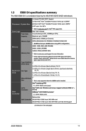
...2666MHz when using 2DPC configurations. 32GB, 16GB, 8GB, 4GB (RDIMM) 64GB, 32GB (LRDIMM) 128GB, 64GB (LRDIMM 3DS) * Refer to www.asus.com for more information ** Actual memory frequency differs from Intel CPU types and memory module. Please check Intel® official site for Intel®... - 8 x SATA 6Gb/s ports (gray) Intel® RSTe (for more detail about the memory types supported by each CPU. 1.3 E900 G4 specifications summary The ASUS E900 G4 is installed. Support software RAID 0, 1, 10 & 5) ASMedia® SATA RAID Controller* - 2 x SATA 6Gb/s ports Optional kits: SAS Controller...
...2666MHz when using 2DPC configurations. 32GB, 16GB, 8GB, 4GB (RDIMM) 64GB, 32GB (LRDIMM) 128GB, 64GB (LRDIMM 3DS) * Refer to www.asus.com for more information ** Actual memory frequency differs from Intel CPU types and memory module. Please check Intel® official site for Intel®... - 8 x SATA 6Gb/s ports (gray) Intel® RSTe (for more detail about the memory types supported by each CPU. 1.3 E900 G4 specifications summary The ASUS E900 G4 is installed. Support software RAID 0, 1, 10 & 5) ASMedia® SATA RAID Controller* - 2 x SATA 6Gb/s ports Optional kits: SAS Controller...
User Manual
Page 15
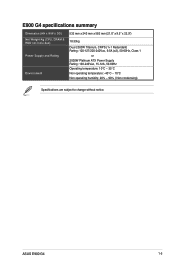
ASUS E900 G4 1-5 E900 G4 specifications summary Dimension (HH x WW x DD) Net Weight Kg (CPU, DRAM & HDD not inclu ded) Power Supply and Rating Environment 532 mm x 243 mm x 582 mm (21.0" x 9.5" x 22.9") 18.33kg Dual 2000W Titanium, CRPS (1+1 Redundant) Rating: 100-127/200-240Vac, 9.5A (x2), 50-60Hz, Class 1 or 2000W Platinum ATX Power Supply Rating: 100-240Vac, 15-12A, 50-60Hz Operating temperature: 10°C ~ 35°C Non operating temperature: -40°C ~ 70°C Non operating humidity: 20% ~ 90% ( Non condensing) Specifications are subject to change without notice.
ASUS E900 G4 1-5 E900 G4 specifications summary Dimension (HH x WW x DD) Net Weight Kg (CPU, DRAM & HDD not inclu ded) Power Supply and Rating Environment 532 mm x 243 mm x 582 mm (21.0" x 9.5" x 22.9") 18.33kg Dual 2000W Titanium, CRPS (1+1 Redundant) Rating: 100-127/200-240Vac, 9.5A (x2), 50-60Hz, Class 1 or 2000W Platinum ATX Power Supply Rating: 100-240Vac, 15-12A, 50-60Hz Operating temperature: 10°C ~ 35°C Non operating temperature: -40°C ~ 70°C Non operating humidity: 20% ~ 90% ( Non condensing) Specifications are subject to change without notice.
User Manual
Page 17
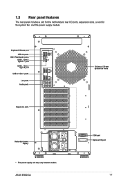
... LINE OUT LINE IN KY Expansion slots 120 mm x 120 mm system fan vents Redundant power supply* * The power supply unit may vary between models ASUS E900 G4 COM port Optional I /O ports, expansion slots, a vent for the motherboard rear I /O port 1-7
... LINE OUT LINE IN KY Expansion slots 120 mm x 120 mm system fan vents Redundant power supply* * The power supply unit may vary between models ASUS E900 G4 COM port Optional I /O ports, expansion slots, a vent for the motherboard rear I /O port 1-7
User Manual
Page 19
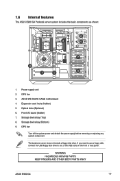
... to use a floppy disk, connect the USB floppy disk drive to any system component. WARNING HAZARDOUS MOVING PARTS KEEP FINGERS AND OTHER BODY PARTS AWAY ASUS E900 G4 1-9 Optical drive (Optional) 6. GPU fan 3. GPU bar Turn off the system power and detach the power supply before removing or replacing any of the USB...
... to use a floppy disk, connect the USB floppy disk drive to any system component. WARNING HAZARDOUS MOVING PARTS KEEP FINGERS AND OTHER BODY PARTS AWAY ASUS E900 G4 1-9 Optical drive (Optional) 6. GPU fan 3. GPU bar Turn off the system power and detach the power supply before removing or replacing any of the USB...
User Manual
Page 23
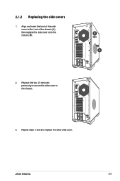
TYPE C 10 USB3.1 USB3.0 USB3.0 SPDIF OUT REAR C/SUB MIC IN LINE OUT LINE 3. Replace the two (2) removed previously to secure the side cover to the front of the side cover to USB BIOS Flashback the chassis. Align and insert the front of the chassis (A), then replace the side cover onto the USB BIOS Flashback 10 USB3.1 chassis (B). Repeat steps 1 and 2 to replace the other side cover. TYPE C USB3.0 USB3.0 SPDIF OUT REAR C/SUB MIC IN LINE OUT LINE 2. 2.1.2 Replacing the side covers 1. ASUS E900 G4 2-3
TYPE C 10 USB3.1 USB3.0 USB3.0 SPDIF OUT REAR C/SUB MIC IN LINE OUT LINE 3. Replace the two (2) removed previously to secure the side cover to the front of the side cover to USB BIOS Flashback the chassis. Align and insert the front of the chassis (A), then replace the side cover onto the USB BIOS Flashback 10 USB3.1 chassis (B). Repeat steps 1 and 2 to replace the other side cover. TYPE C USB3.0 USB3.0 SPDIF OUT REAR C/SUB MIC IN LINE OUT LINE 2. 2.1.2 Replacing the side covers 1. ASUS E900 G4 2-3
User Manual
Page 25
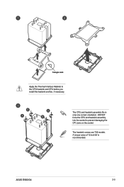
The heatsink screws are T30 models. Triangle mark Apply the Thermal Interface Material to prevent damaging the CPU pins on the socket. A torque value of 12 inch-lbf is recommended. DO NOT force the CPU and heatsink assembly into the socket to the CPU heatsink and CPU before you install the heatsink and fan, if necessary. ASUS E900 G4 2-5 The CPU and heatsink assembly fits in only one correct orientation.
The heatsink screws are T30 models. Triangle mark Apply the Thermal Interface Material to prevent damaging the CPU pins on the socket. A torque value of 12 inch-lbf is recommended. DO NOT force the CPU and heatsink assembly into the socket to the CPU heatsink and CPU before you install the heatsink and fan, if necessary. ASUS E900 G4 2-5 The CPU and heatsink assembly fits in only one correct orientation.
User Manual
Page 27
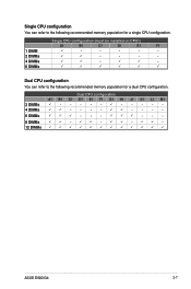
... CPU configuration You can refer to the following recommended memory population for a dual CPU configuration. P - - - - 4 DIMMs P P - - - - PP - PPP - - - 8 DIMMs PP - P P - - - - 6 DIMMs PPP - - - PP - 12 DIMMs P P P P P P P P P P P P ASUS E900 G4 2-7 Single CPU configuration (must be installed on CPU1) A1 B1 C1 D1 E1 F1 1 DIMM P - - - - - 2 DIMMs P P - - - - 4 DIMMs P P -
... CPU configuration You can refer to the following recommended memory population for a dual CPU configuration. P - - - - 4 DIMMs P P - - - - PP - PPP - - - 8 DIMMs PP - P P - - - - 6 DIMMs PPP - - - PP - 12 DIMMs P P P P P P P P P P P P ASUS E900 G4 2-7 Single CPU configuration (must be installed on CPU1) A1 B1 C1 D1 E1 F1 1 DIMM P - - - - - 2 DIMMs P P - - - - 4 DIMMs P P -
User Manual
Page 29
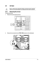
ASUS E900 G4 2-9 Remove the fan connector from the fan. 2. Failure to do so may cause damage to unplug the power cable before installing or removing any system components. Remove the two (2) screws from the FRNT_FAN3 connector on the motherboard. 2.4 Air Duct Ensure to the motherboard and other system components! 2.4.1 Removing the air duct To remove the air duct: 1.
ASUS E900 G4 2-9 Remove the fan connector from the fan. 2. Failure to do so may cause damage to unplug the power cable before installing or removing any system components. Remove the two (2) screws from the FRNT_FAN3 connector on the motherboard. 2.4 Air Duct Ensure to the motherboard and other system components! 2.4.1 Removing the air duct To remove the air duct: 1.
User Manual
Page 31
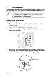
Installing 3.5-inch storage devices To install 3.5-inch storage devices: 1. Screw holes (HDD) HDD notches (Storage device tray) ASUS E900 G4 2-11 Prepare the 3.5-inch storage device and the bundled set of the chassis. Refer to the Removing the side cover section for the optional four (4) ...
Installing 3.5-inch storage devices To install 3.5-inch storage devices: 1. Screw holes (HDD) HDD notches (Storage device tray) ASUS E900 G4 2-11 Prepare the 3.5-inch storage device and the bundled set of the chassis. Refer to the Removing the side cover section for the optional four (4) ...
User Manual
Page 33
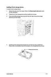
... side cover section for the location of the chassis. Remove the side cover of the storage device tray lock pin. Storage device tray lock pin ASUS E900 G4 2-13 Installing 2.5-inch storage devices To install 2.5-inch storage devices: 1.
... side cover section for the location of the chassis. Remove the side cover of the storage device tray lock pin. Storage device tray lock pin ASUS E900 G4 2-13 Installing 2.5-inch storage devices To install 2.5-inch storage devices: 1.
User Manual
Page 35
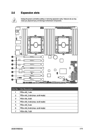
Slot No. at x8 mode) 3 PCIe x16_3 slot 4 PCIe x16_4 slot (max. at x8 mode) 5 PCIe x16_5 slot 6 PCIe x16_6 slot (max. Slot Description 1 PCIe x16_1 slot 2 PCIe x16_2 slot (max. 2.6 Expansion slots Unplug the power cord before adding or removing expansion cards. Failure to do so may cause you physical injury and damage motherboard components. at x8 mode) 7 PCIe x16_7 slot ASUS E900 G4 2-15
Slot No. at x8 mode) 3 PCIe x16_3 slot 4 PCIe x16_4 slot (max. at x8 mode) 5 PCIe x16_5 slot 6 PCIe x16_6 slot (max. Slot Description 1 PCIe x16_1 slot 2 PCIe x16_2 slot (max. 2.6 Expansion slots Unplug the power cord before adding or removing expansion cards. Failure to do so may cause you physical injury and damage motherboard components. at x8 mode) 7 PCIe x16_7 slot ASUS E900 G4 2-15
User Manual
Page 37
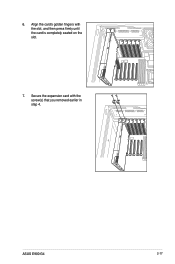
Secure the expansion card with the slot, and then press firmly until the card is completely seated on the slot. 7. ASUS E900 G4 2-17 Align the card's golden fingers with the screw(s) that you removed earlier in step 4. 6.
Secure the expansion card with the slot, and then press firmly until the card is completely seated on the slot. 7. ASUS E900 G4 2-17 Align the card's golden fingers with the screw(s) that you removed earlier in step 4. 6.
User Manual
Page 39
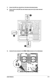
Secure the fan to the FRNT_FAN3 connector on the motherboard. Connect the fan connector to the GPU bar and chassis using the four (4) screws removed previously. 12. 11. Secure the GPU bar using the two (2) screws removed previously. 13. ASUS E900 G4 2-19
Secure the fan to the FRNT_FAN3 connector on the motherboard. Connect the fan connector to the GPU bar and chassis using the four (4) screws removed previously. 12. 11. Secure the GPU bar using the two (2) screws removed previously. 13. ASUS E900 G4 2-19
User Manual
Page 41
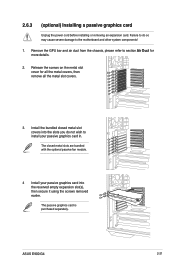
... the slots you do so may cause severe damage to section Air Duct for all the metal covers, then remove all the metal slot covers. 3. ASUS E900 G4 2-21
... the slots you do so may cause severe damage to section Air Duct for all the metal covers, then remove all the metal slot covers. 3. ASUS E900 G4 2-21
User Manual
Page 43
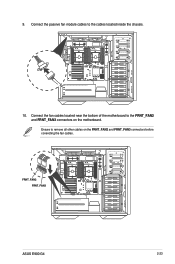
Connect the passive fan module cables to the FRNT_FAN2 and FRNT_FAN3 connectors on the FRNT_FAN2 and FRNT_FAN3 connectors before conencting the fan cables. Connect the fan cables located near the bottom of the motherboard to the cables located inside the chassis. 10. FRNT_FAN2 FRNT_FAN3 ASUS E900 G4 2-23 9. Ensure to remove all other cables on the motherboard.
Connect the passive fan module cables to the FRNT_FAN2 and FRNT_FAN3 connectors on the FRNT_FAN2 and FRNT_FAN3 connectors before conencting the fan cables. Connect the fan cables located near the bottom of the motherboard to the cables located inside the chassis. 10. FRNT_FAN2 FRNT_FAN3 ASUS E900 G4 2-23 9. Ensure to remove all other cables on the motherboard.
User Manual
Page 45
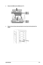
Remove the DIMMs from the right side of the system. 3. ASUS E900 G4 2-25 DIMM_F1 DIMM_E1 DIMM_D1 DIMM_A1 DIMM_B1 DIMM_C1 4. Remove the two (2) bay screws securing the riser card tray from the DIMM slots A1-F1.
Remove the DIMMs from the right side of the system. 3. ASUS E900 G4 2-25 DIMM_F1 DIMM_E1 DIMM_D1 DIMM_A1 DIMM_B1 DIMM_C1 4. Remove the two (2) bay screws securing the riser card tray from the DIMM slots A1-F1.
User Manual
Page 47
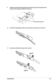
Connect two (2) OCuLink cables to the 4-pin power connector on the riser card tray, then secure the riser card to the tray using the bundled two (2) screws. OCUPCIE2 OCUPCIE1 ASUS E900 G4 2-27 Connect the bundled power cable to the riser card. 9. Align the riser card with the screw holes on the riser card. 11. Riser card tray screw holes 10.
Connect two (2) OCuLink cables to the 4-pin power connector on the riser card tray, then secure the riser card to the tray using the bundled two (2) screws. OCUPCIE2 OCUPCIE1 ASUS E900 G4 2-27 Connect the bundled power cable to the riser card. 9. Align the riser card with the screw holes on the riser card. 11. Riser card tray screw holes 10.
User Manual
Page 49
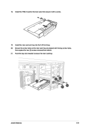
Install the riser card and tray into the 5.25-inch bay. 20. ASUS E900 G4 2-29 Ensure the screw holes on the riser card tray are aligned with a screw. 19. Push the bay lock inwards to the riser card, then secure it with the bay screw holes, then replace the two (2) screws removed from before. 21. Install the PIKE II card to secure the riser card tray. 18.
Install the riser card and tray into the 5.25-inch bay. 20. ASUS E900 G4 2-29 Ensure the screw holes on the riser card tray are aligned with a screw. 19. Push the bay lock inwards to the riser card, then secure it with the bay screw holes, then replace the two (2) screws removed from before. 21. Install the PIKE II card to secure the riser card tray. 18.
User Manual
Page 51
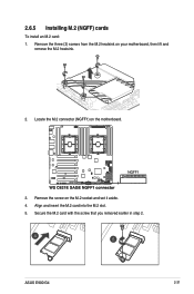
Remove the three (3) screws from the M.2 heatsink on the motherboard. 3. Locate the M.2 connector (NGFF1) on your motherboard, then lift and remove the M.2 heatsink. 2. Secure the M.2 card with the screw that you removed earlier in step 2. Remove the screw on the M.2 socket and set it aside. 4. ASUS E900 G4 2-31 Align and insert the M.2 card into the M.2 slot. 5. 2.6.5 Installing M.2 (NGFF) cards To install an M.2 card: 1.
Remove the three (3) screws from the M.2 heatsink on the motherboard. 3. Locate the M.2 connector (NGFF1) on your motherboard, then lift and remove the M.2 heatsink. 2. Secure the M.2 card with the screw that you removed earlier in step 2. Remove the screw on the M.2 socket and set it aside. 4. ASUS E900 G4 2-31 Align and insert the M.2 card into the M.2 slot. 5. 2.6.5 Installing M.2 (NGFF) cards To install an M.2 card: 1.
User Manual
Page 53
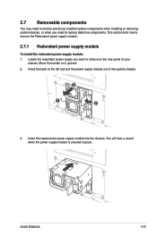
... section tells how to the left and pull the power supply module out of your chassis. Insert the replacement power supply module into the chassis. ASUS E900 G4 2-33 Move the handle on the rear panel of the system chassis. 2 2 1 2 1 2 3. Locate the redundant power supply you need to remove previously installed system components...
... section tells how to the left and pull the power supply module out of your chassis. Insert the replacement power supply module into the chassis. ASUS E900 G4 2-33 Move the handle on the rear panel of the system chassis. 2 2 1 2 1 2 3. Locate the redundant power supply you need to remove previously installed system components...


